Loading ...
Loading ...
Loading ...
TROUBLESHOOTING & REFERENCES
J-17
ENGLISH
Outdoor Unit Error Codes
Error Code 42 & 43
The low pressure switch will generate an Error Code 43 if
open. An open high pressure switch will show an Error Code
42.
Testing Procedure
If the system generates either of these two codes, check the
continuity of the switch to ensure it is not open or shorted.
High or low pressures are usually related to dirt in the coils,
dirt in the air lter, or incorrect refrigerant charge.
There are no pressure ports that can be accessed to measure
low pressure in heat mode nor high pressure in cool mode. If
the system trips on one of these errors, it will be necessary to
remove the refrigerant and re-charge to conrm low or high
charge is not causing the problem.
Error Code 44
The system is operating at excessive refrigerant pressure. If
the system is a new installation, it is likely that the charge is
too high. Note the Weight Method is the ONLY way to charge
this system.
Typical Causes of High Pressure in Cooling Mode:
• Overcharge
• Dirty outdoor coil
• Restriction
Typical Causes of High Pressure in Heating Mode:
• Overcharge
• Undersized refrigerant lines or excessive length
• Restriction
Note: If the refrigerant pressures are correct, yet the system
does not close the error reporting pressure switch, replace the
defective pressure switch.
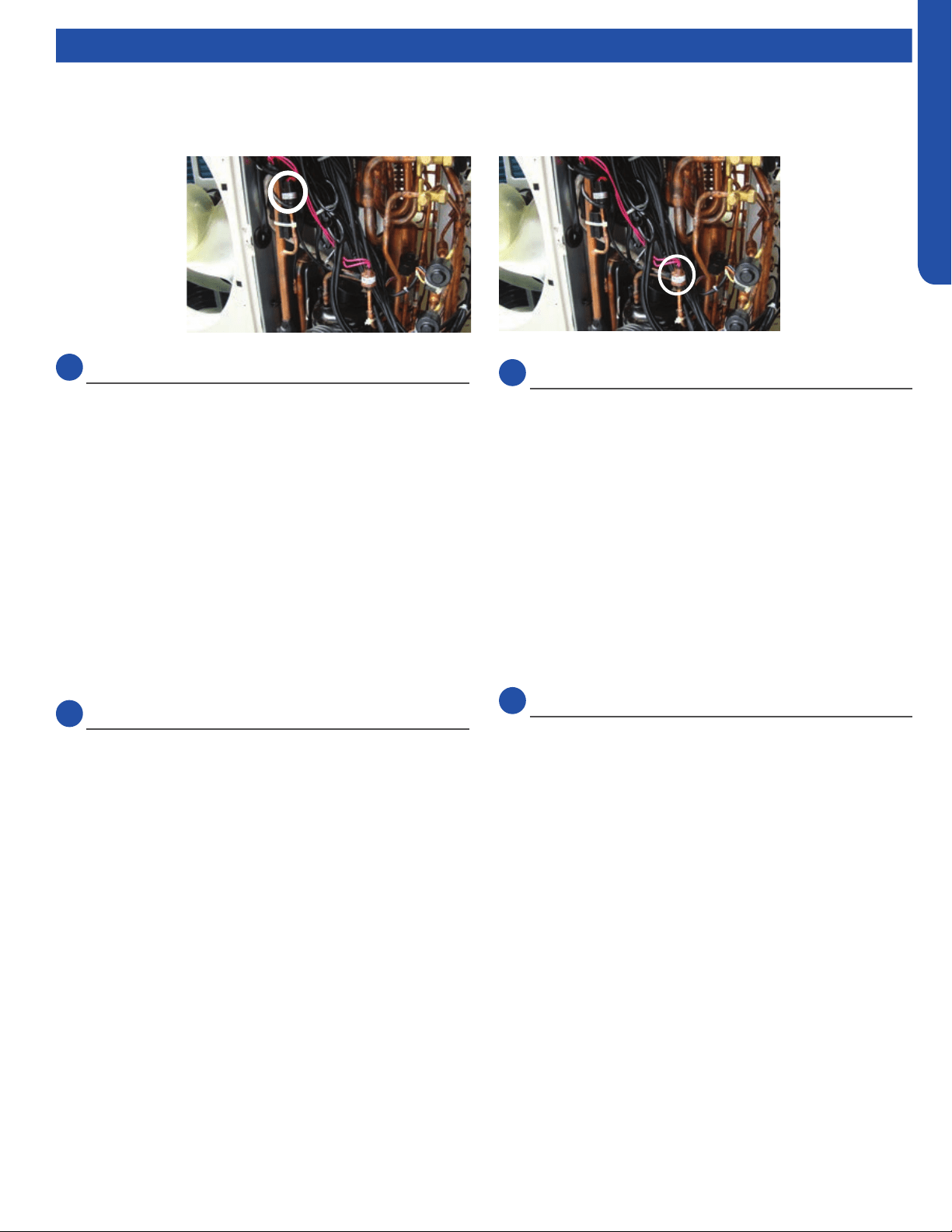
LowLow
PressurePressure
SwitchSwitch
High Pres-High Pres-
suresure
SwitchSwitch
Error Code 45
This code is indicating that system pressure is too low.
Typical Causes of Low Pressure in Cooling Mode:
• Lack of charge
• Low Heat on Indoor coil
• Restrictions, air ow, or dirt
• Low indoor load
Typical Causes of Low Pressure in Heating Mode:
• Cold outdoor air
• Lack of charge
• Restriction
Pressure-Related Error Codes
To protect the compressor, the PCB has a low pressure switch connection at CN13, and a high pressure switch connection at
CN12.
Communication Error Code
Error Code 15
Data travels between the units on the terminal block
connections 3/C and 1. A correct connection for each unit is
indicated by a solid green LED on the Service Monitor Board.
If an LED is ashing or not on, make sure the 14/4 stranded
copper communication cable connections are tight and
on the correct terminals. Additionally, ensure there are no
splices in the 3/C wire, and that the PCB connections at CN21
are in good order. An incomplete or inadequate ground can
easily be an issue.
Loading ...
Loading ...
Loading ...