Loading ...
Loading ...
Loading ...
LARGE CASSETTE TECHNICAL OVERVIEW
E-7
ENGLISH
25
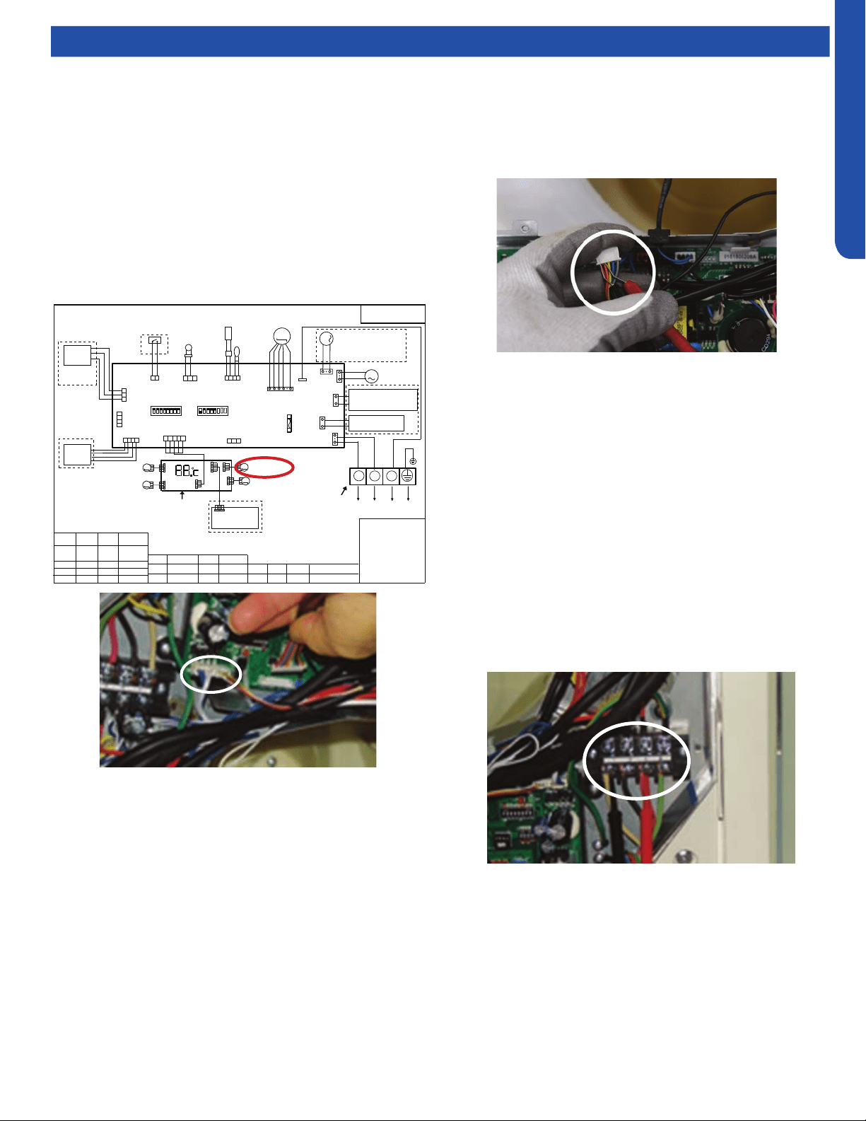
PCB Conguration
TO OUT DOOR UNIT
SW1-1
TYPE DEFINE
Cassette
Y/G:YELLOW/GREEN
RD:RED WHT:WHITE
BLK:BLACK
******************
.
SENSOR
CN1
CN11
CN19
SW3(BM3)
2
1
3
BLK
WHT
RD
NOTE:
1.DASHED PARTS ARE OPTIONAL.
2.USER SHOULD NOT CHANGE THE
DIP SWITCH SW1 SW3 WITHOUT GUIDENCE
3.SW3-5->SW3-8 ARE USED FOR WIRED CONTROLLER
ADRESS SELECT. SW3-1->SW3-4 ARE RESERVED.
CH1
OFF
OFF
TEMP
.
PIPING
DC FAN MOTOR
BA
C
87654321
SW1(BM1)
87654321
N
(SLIM)
Room card
available
ON
Y/G
0150516956U
L
I.R .RECEIVER
(WITH DIGITAL
DISPLAY)
WiFi
MODULE
.
B
A
C
WIRED
CONTROLLER
M
SENSOR
TEMP
.
ROOM
ROOM CARD
CN3
CN6
T5A 250VAC
CN16
DRAIN
PUMP
M
CN9
CN10
CN4
CN14
FUSE
FLOAT
SWITCH
CN13
CN4
CN3
CN2
CN7
CN1
CN6
INTELLIGENT
MOVE EYE DEVICE
M
M
LOUVER
STEP MOTOR4
LOUVER
STEP MOTOR3
M
M
LOUVER STEP
MOTOR2
LOUVER STEP
MOTOR1
INDOOR UNIT
MAIN CONTROL
BOARD
I.R .RECEIVER :
INFRARED REMOTE
RECEIVER .
TEMP.:TEMPERATURE
ON
OFF
ON
CN26
A
B
M
FRESH AIR MOTOR /
EXTERNAL ALARM OUTPUT
(FUNCTION IN FUTURE )
( Contact rating_230VAC,3A)
CAPACITY
(BTU/H)
SW1-2
SW1-3
OFF ON
ON
ON
ON
ON
SW1-4
unavailable
OFF
ON
SW1-5
COOL HEAT
COOL ONLY
HEAT PUMP
SW1-6
SW1-7
SW1-8
OFF
OFF
INDOOR UNIT
TERMINAL BLOCK
CN8
24000
ON
ON
OFF
ELECTRIC HEATING TERMINAL
RATING_230VAC,3A
CONNECT TO THIRD PARTY RELAY
CN15
ELECTRIC HEATING
THERMOSTAT / FUSE
OFF
36000
42000
48000
ON
ON
ON
Testing
Testing Louver Motors
If the louver does not operate with command from the remote
control, either the indoor board is bad, or the louver motor
is defective. It is more likely the motor is defective than the
board. (Make sure the louver assembly is not binding and
keeping the vanes from moving.)
1. Remove power from the unit and remove the indoor unit
cover.
2. Access the circuit board.
3. Identify the inoperable louver motor on the schematic
drawing below and disconnect the plug from the circuit
board.
4. Use an Ohmmeter to test the electrical continuity of the
louver motor windings. The proper resistance for each
winding can be found in this table. If the motor winding
resistance is erratic or shows open, the motor is defective.
Replace the motor.
5. If the motor checks out good, replace the indoor control
board.
Testing Communication Circuit
If an Error E7 occurs, perform the following test to determine
if the indoor control board is functioning properly to send data
to the outdoor unit.
Perform this test with the unit powered and all wiring
connected between indoor and outdoor unit.
Make sure all wiring between the indoor and outdoor unit
are correct. There should no splices between the indoor and
outdoor unit wiring connecting terminals 1 or 3. Make sure
wiring is correct, before performing this test.
1. Measure the DC voltage between terminals 1 and 3 on the
indoor terminal block.
2. The voltage should uctuate between 8VDC and 23VDC.
The uctuating signal indicates a good communication
path.
3. If the voltage does not uctuate, and the wiring is good,
the indoor board is defective.
Loading ...
Loading ...
Loading ...