Loading ...
Loading ...
Loading ...
MID-STATIC DUCTED TECHNICAL OVERVIEW
G-2
ENGLISH
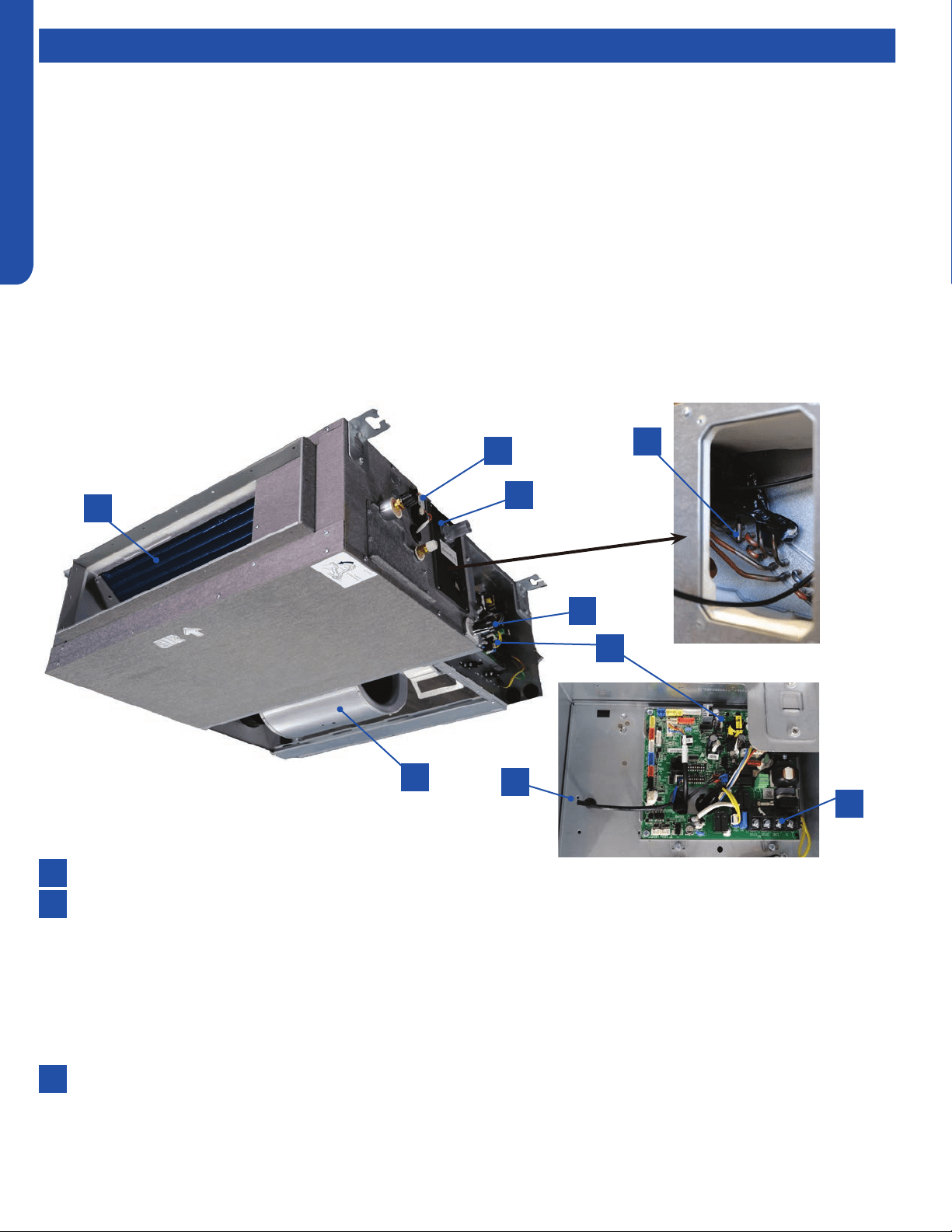
ComponentsComponents
The Mid-Static Ducted Indoor Unit will act as evaporator coils during cooling mode and condenser coils during heating mode.
This unit can operate with a motorized supply air louver or it can have a LIMITED amount of ducting added to the unit’s return
and supply air duct connection anges. The return air ducting can be connected to the end of the cabinet or the bottom blank o
plate can be removed for bottom return conguration.
DIP Switches on the unit’s circuit board congure the fan power to match the ducting conguration.
These units have a built in condensate pump with an associated condensate level switch. The condensate pump is capable of
lifting water out of the indoor unit. If high water lift is needed, the water from the cassette pump should be pumped into a eld
supplied condensate pump with high lift power.
The layout of the system is very straightforward and components are easily accessed should service be required. The blower
assembly and room air temperature sensor is accessed at the rear of the evaporator coil, and the piping temperature sensor
is located under the top cover. The condensate pump and oat switch are accessed under the removable panel next to the
electrical control box.
The wired controller can be congured to sense room air temperature. There is no option for use with remote control.
All operating status and information is displayed on the wired controller. The Mid-Static Ducted unit does not have a display.
8
9
6
4
2
2
7
5
3
3
1
1
Evaporator Coil
Blower Assembly
The indoor unit features a DC variable speed dual shaft blower motor that will change speed to match the capacity demand
from the outdoor unit. The motor is a dual shaft type that powers two individual blower assemblies.
The blower assembly consists of 2 plastic blowers. A set screw holds each blower wheel to the blower motor.
The indoor blower motor is connected to the indoor unit control board. The wiring from the motor to indoor board consists
of 5 wires connected to pins that deliver line voltage, speed, and feedback information.
During normal operation, the indoor control board will energize the indoor blower motor and request proper speed. Fan
power should be set using the DIP Switches SW1 settings.
Terminal Block
Power to operate the indoor unit comes from the electrical line voltage terminal block at the outdoor unit. The wiring
includes 4 wires, 1, 2, 3 and ground. Wires 1 and 3 complete the data path. These wires should always be 14 gauge AWG
Stranded type wire. Splices in wires 1 or 3 may cause communication errors.
Component Overview
Loading ...
Loading ...
Loading ...