Loading ...
Loading ...
Loading ...
LARGE CASSETTE TECHNICAL OVERVIEW
E-4
ENGLISH
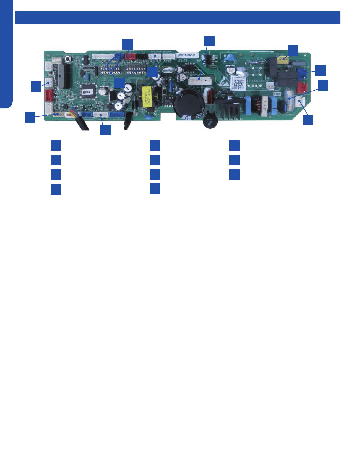
Components
Power
Communication Terminal
3.15A 250V Fuse
CN3 Pipe/Room Temp Sensors
1
4
2
5
3
7
10
8
6
9
CN19 Float Switch
CN11 Wired Remote
DIP Switches
CN36 Stepper Motor
11
CN6 Fan Motor
CN9 Condensate Pump
CN14 Panel Connection
Cassette Unit Indoor Circuit Board
1
3
2
10
11
9
6
7
5
4
8
The indoor unit circuit board controls the switching functions of
the indoor unit. All control decisions are made by the outdoor
unit ECU. The indoor board has some limited diagnostic
capability which will be covered in this manual.
The Indoor Unit Circuit Board communicates with the outdoor
unit ECU via a connection at Terminal Block screw 3. The
data pulse that sends the communication information can be
measured with a voltmeter placed to DCV range. From the
ground connection at the Terminal Block to the Number 3 screw
connection, the voltage should pulse up and down when data is
being transmitted.
This control board has control over the fan louver movement,
manual fan blower control, indoor coil temperature and indoor
air temperature sensing functions. All operational decisions are
controlled by the OUTDOOR UNIT ECU.
The connections on the indoor board are shown here in the
schematic drawing.
Line voltage to power the indoor unit comes in on Terminal
Block connections 1 and 2. Power connects from these terminal
connections to CH- 3 and CH-4 on the circuit board. If the
board does not respond to commands and has no display, check
for line voltage at these connections. When power is present at
the indoor board, the Display Power Indicator will be lit.
The control board has a replaceable 3.15A 250V fuse that
protects against excessive current. If power is present at
the board but the board does not work, check for continuity
through the fuse. Replace if the fuse is open.
The indoor unit temperature sensors are connected at
Plug CN-13. When testing the calibration of these sensors,
the wires can be released from the plug by pressing on the
tension tab on the side of the plug.
The receiver/display unit that is mounted to the front cover
of the indoor unit plugs into the circuit board via a connection
at Plug CN-29.
There is one motor that controls the movement of the
louvers. The motor connects to the circuit board at Plug CN-
14. The motor is located in the over of the louver assembly.
The blower/fan motor is connected to the circuit board at
plug CN-11.
The Cassette unit has a built in condensate pump. The pump
is connected to the circuit board on Plug CN-9. The pump is
energized whenever the Float Switch indicates that water
needs to be pumped from the cassette. The oat switch
connects onto the circuit board via Plug CN-18.
Loading ...
Loading ...
Loading ...