Loading ...
Loading ...
Loading ...
OUTDOOR TECHNICAL OVERVIEW
B-21
ENGLISH
Topic Title
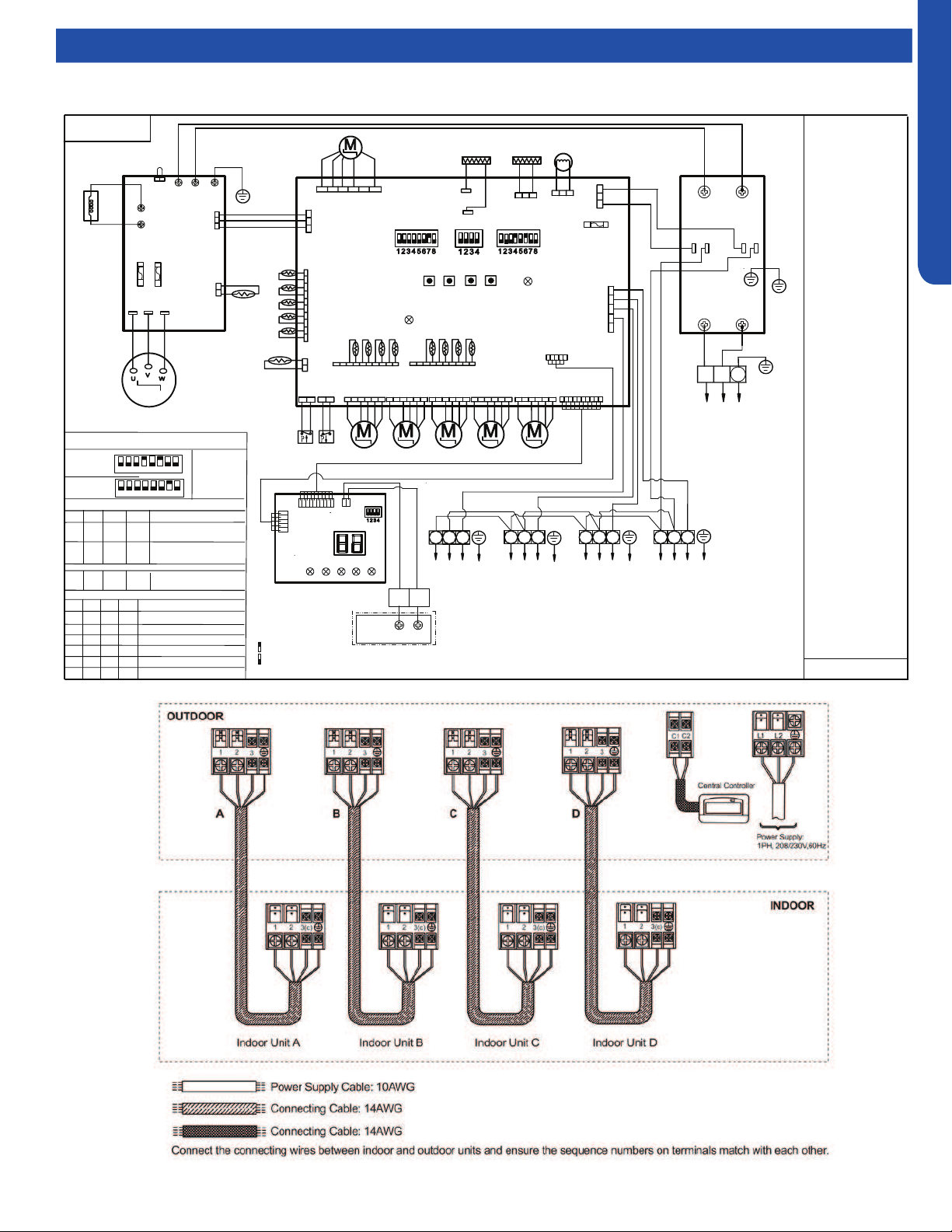
Wiring Diagrams
4U36EH2VHA
LP
HP
CN9
GND
CN11
CON8
CN5
MAIN CONTROL BOARD
4-WAY
VALVE
DC FAN
MOTOR
250VAC T5A
FUSE
CON9
FG
Vsp
Vcc
ON ON
Vdc
L1 L2
Power supply
CN2
SW7
COMPRESSOR
CN15
CRANKCASE
HEATER
2
1
3
POWER FILTER
BOARD
P4
P2
P3
P1
ON
W
B
2
1
3
BL Y W
B
R
G
Y/G
Y/G
Reactor
L2
CN6
CN4
BL
BL
R
GRY
OR
OR
BASE PAN
HEATER
CN1 ( TC1)
CN24( TC2)
E.E.V-O
E.E.V-A
E.E.V-B E.E.V-C
DRIVE MODULE
P
1
1
T20A/250VAC
COMM.
T
fin
L1
Tc
CN14
D
CN13
E.E.V-D
CN16 CN17 CN18 CN19
CN8
B
W
R
31
2
To Indoor
Unit A
31
2
CN23
CN21
ON
To Indoor
Unit B
To Indoor
Unit C
To Indoor
Ts
Ta
Td
T
e
C B A
D C B A
LED2
SW6 SW5
U V W
SERVICE
DISPLAY
BOARD
A B
CN3
CN2
CN4
Sensor abbreviation :
Tc: Condensing Temp.
Ts: Compressor Suction
Temp.
Ta: Ambient Temp.
Td: Compressor Discharge
Te: Defrosting Temp.
Tfin: Module Temp.
TC1:Condensing Temp.
for Indoor Units A/B/C/D
Toci: Outdoor
Condensing inlet Temp.
Other abbreviation:
OR: Orange,Y/G:
Yellow/Green,W: White,
Y: Yellow, BR: Brown,
B: Black, BL: Blue,
GR:Green ,GRY:GREY
R: Red E.E.V:Electro
expansion valve,
LP/HP:
Low /high pressure switch
Note:
1.Dashed parts are
optional.
2.Please refer to
service manual to get
details of the DIP
switches .
3.Do not change the
DIP switches setting
without technical
support.
4.The LED1-LED5 in
the service display
board in turn
corresponds to the
communication status
of ndoor unitA,B,C,D.
LED will not lit if
communication
abnormal.
SW1 SW2 SW3 SW4
Start/+
Stop/-
FA
Y/G
R
EARTH
L1 L2
L1’
(Gas Pipe)
TC2:Condensing Temp.
for Indoor Units A/B/C/D
(Liquid Pipe)
Definition of Dispaly board SW1
SW1-1
SW1-2
SW1-3
SW1-4
Normal Operating(default)
OFF
OFF
OFF
OFF
ON
OFF
OFF
OFF
OFF
ON
OFF
OFF
OFF
OFF
ON OFF
Manually forced Heating
Manually forced Cooling
Rated Operating(fixed speed)
OFF
OFF
ON
OFF
Time Defrost Valid
4U36EH2VHA1
SW5
1
2
3
4 5
6
7
8
ON
SW7
1
2
3
4 5
6
7
8
ON
Factory defaultof main control board SW5 & SW7
Unit D
Remote
central
A
B
controller
0150538688
0150538688
LED1
GR
Other detail s about the service information please please refer to technical service mannual.
Centralized control address
SW6-1
SW6-2
SW6-3
SW6-4
OFF
OFF
OFF
OFF
Definition of main control board SW6
Indoor unit address group1
( NO.1-NO.5) (default)
ON
OFF
OFF OFF
Indoor unit address group2
( NO.6-NO.10)
……
ON
ON
ON ON
Indoor unit address group
16( NO.76-NO.80)
R
W
B
B
W
W
5V(V+)
COM
GND
Toci
B
BL
W
CN7
W R R
Y
GR
BL
W
W
W
pin1
W
R
R
R
R
R
R
W
A
B
C
D
ON
ON
ON
ON
IDU&ODU Wiring Error Check
C1
C2
R
W
GR
W
MAIN side pin1-DISPLAY side pin5
pin1
SW1
B
W
B
B
W
W
B
LED5
SMG1
ON
ON
Means switch at ON position
Means switch at OFF position
R
W
B
pin1
pin1
pin1
W
B
W
B
B
ACL(L1)
ACL(L2)
CN12
R
Y
L2’
T20A/250VAC
LED4
LED3
LED2
LED1
FAN
Loading ...
Loading ...
Loading ...