Loading ...
Loading ...
Loading ...
TROUBLESHOOTING & REFERENCES
J-21
ENGLISH
Topic Title
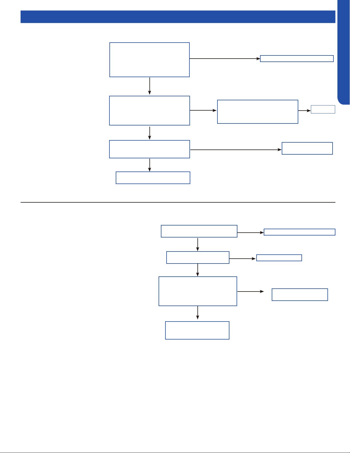
Flow Charts
Adjust communication wire
Is the compressor drive module
input power normal (Test the
AC power supply voltage of the
module’s power input ACL-ACN:
normal value should between 196-
253VAC)?
Check the AC voltage between
the two terminals of power filter
board board P7& the terminal 3
of relay RL1 (208-230VAC)
Ye s
Normal
No
Is the AC power supply wire
between compressor drive
module and filter
board firmly connected?
Fix wiring
Abnormal
Check if the output of main
control board CN6,CN34 are
both DC 12V
No
Main control board
is bad, replace.
No
The filter board is broken,
replace the filter board
No
[4] Communication abnormal between PCB and IPM
Control board can not
communicate with the
compressor driver module for
over 4 minutes
Possible causes:
• The communication wire is bad
• The PCB is bad
• The power module is bad
Correct power supply
Is power supply voltage
normal?
Is electric box wiring
correct?
Is power module voltage
between terminal P&N more
than 390V or less than 160V
during operation?
Correct the wiring
Replace power
module
Ye s
Ye s
No
No
Check rectifier, rector,
electrolytic capacitor on
inverter main circuit
No
Ye s
[6] DC voltage or AC voltage high
Driver module AC power supply voltage over 280VAC,
or driver module DC-BUS voltage over 390VDC.
Possible causes:
• The power supply is abnormal
• Incorrect wiring
• Power module is bad
Loading ...
Loading ...
Loading ...