Loading ...
Loading ...
Loading ...
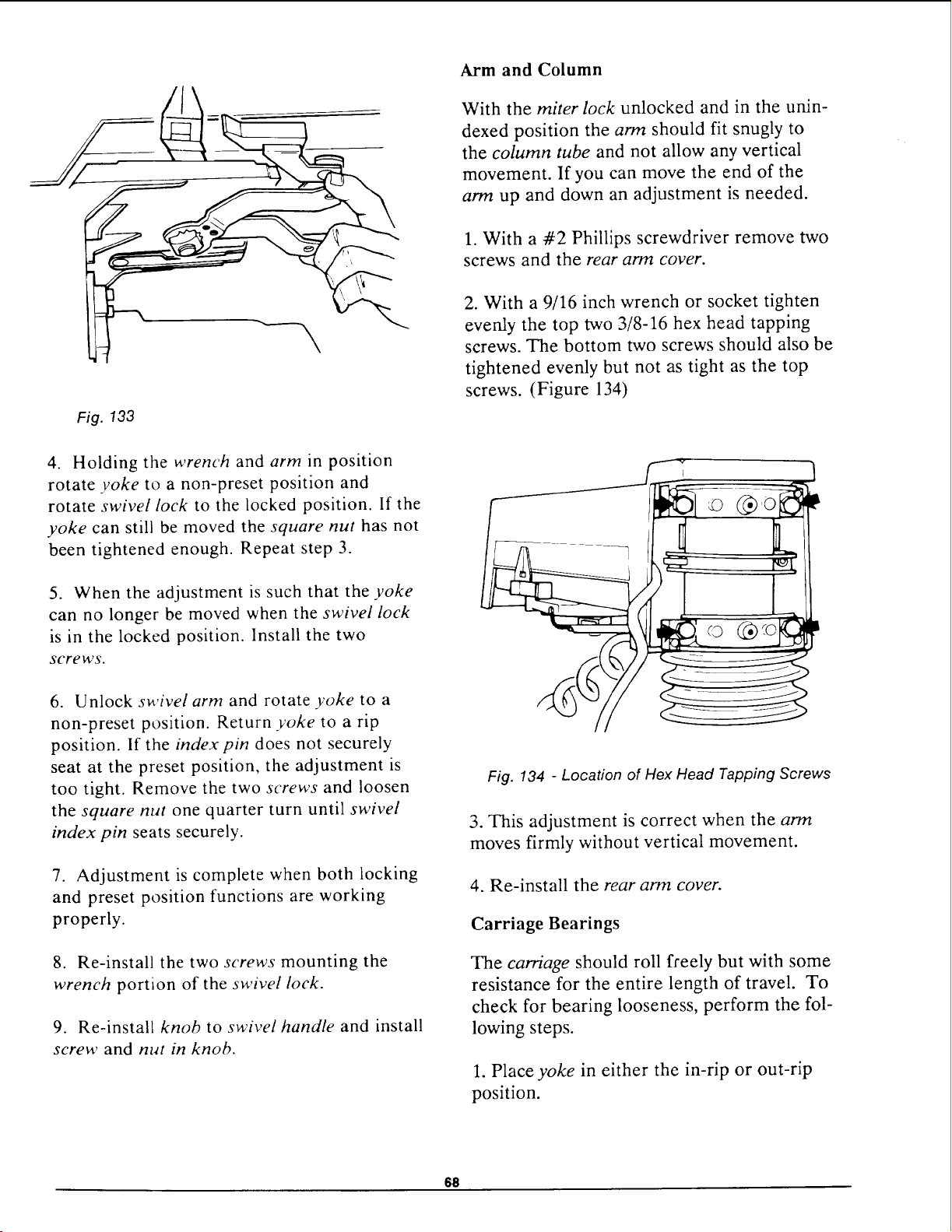
Fig. 133
4. Holding the wrench and arm in position
rotate yoke to a non-preset position and
rotate swivel lock to the locked position. If the
yoke can still be moved the square nut has not
been tightened enough. Repeat step 3.
5. When the adjustment is such that the yoke
can no longer be moved when the swivel lock
is in the locked position. Install the two
screws.
6. Unlock swivel arm and rotate yoke to a
non-preset position. Return yoke to a rip
position. If the index pin does not securely
seat at the preset position, the adjustment is
too tight. Remove the two screws and loosen
the square nut one quarter turn until swivel
index pin seats securely.
7. Adjustment is complete when both locking
and preset position functions are working
properly.
8. Re-install the two screws mounting the
wrench portion of the swivel lock.
9. Re-install knob to swivel handle and install
screw and nut in knob.
Arm and Column
With the miter lock unlocked and in the unin-
dexed position the arm should fit snugly to
the column tube and not allow any vertical
movement. If you can move the end of the
arm up and down an adjustment is needed.
1. With a #2 Phillips screwdriver remove two
screws and the rear arm cover.
2. With a 9/16 inch wrench or socket tighten
evenly the top two 3/8-16 hex head tapping
screws. The bottom two screws should also be
tightened evenly but not as tight as the top
screws. (Figure 134)
© @o
Fig. 134 - Location of Hex Head Tapping Screws
3. This adjustment is correct when the arm
moves firmly without vertical movement.
4. Re-install the rear arm cover.
Carriage Bearings
The carriage should roll freely but with some
resistance for the entire length of travel. To
check for bearing looseness, perform the fol-
lowing steps.
1. Place yoke in either the in-rip or out-rip
position.
611
Loading ...
Loading ...
Loading ...