
Loading ...
Loading ...
Loading ...
©
2019 DJI All Rights Reserved.
15
ROBOMASTER S1
User Manual
7. PWM Output Port
The S1 motion controller enables the duty cycle to be set through the Scratch or Python program
using the PWM output port.
8. S-Bus Port
Reserved port.
9. M0 Port
Reserved port.
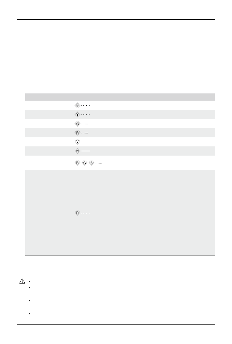
10. LED indicator
Used to indicate the status of the S1 motion controller.
LED indicator Motion controller status
Blinks blue slowly
Working normally
Blinks yellow slowly
Running autonomous program
Blinks green quickly
IMU calibration successful
Blinks red quickly
IMU calibration failed
Solid yellow
IMU is calibrating
Solid white
Firmware updating
Blinks red, green,
and blue alternatively
No attitude information input
Blinks red slowly
Stop Mode*
Stop mode may occur in the following situations:
a. Motion controller is disconnected from or cannot
communicate with motor.
b. S1 cannot move due to the motor hardware
abnormality.
c. Motion controller cannot communicate with the
gimbal.
d. Motion controller cannot communicate with the
remote controller.
e. Abnormal motion controller attitude.
f. Motion controller cannot communicate with the
battery.
* Stop mode warning prompts will display in the app, go to Settings then System to check the
corresponding error.
Connect the black and orange cables to the ports of the corresponding color.
Make sure the motion controller is properly installed before use and the screws on the
chassis rear cover are locked.
After each reinstallation of the motion controller, calibrate the S1 if prompted to do so in the
RoboMaster app. Refer to the Gimbal and Chassis Calibration section for more information.
To avoid dislodging the motion controller when removing the rear chassis cover, lift the cover
carefully before removing.
Loading ...
Loading ...
Loading ...