Loading ...
Loading ...
Loading ...
7
1
Part Names and Functions
This chapter describes the part names and functions of this POS terminal.
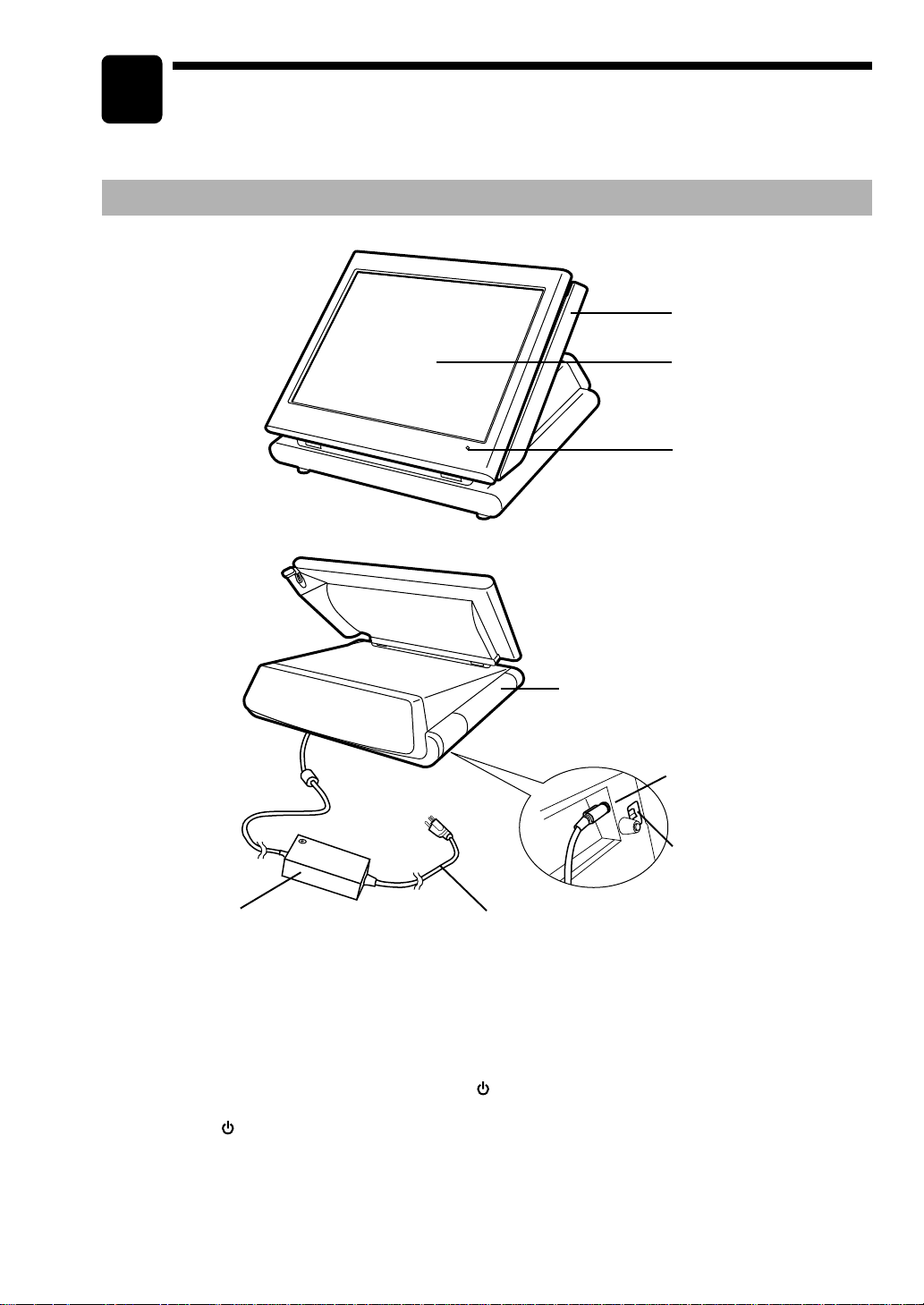
External View
■■
■■
■ Front view
■■
■■
■ Rear view
Magnetic card reader
Operator display (touch panel)
Power indicator
Mode switch
(located at the bottom cabinet)
Side cover
AC adapter
AC power cord
AC adapter jack
AC power cord
Plug the AC adapter connector into the AC adapter jack, then plug the AC power cord into the wall outlet
that has a dedicated earth ground.
Mode switch
The switch has the position ON ( I ) and STANDBY ( ).
Set the mode switch to the ON ( I ) position after the terminal has been plugged into the wall outlet.
The STANDBY (
) position locks all operations of the POS terminal. When you select this position, the
screen will disappear.
Power indicator
When the POS terminal is plugged in, the power indicator at the lower right corner of the LCD panel will
light up. The power indicator will remain on while the display’s backlight is off.
Loading ...
Loading ...
Loading ...