Loading ...
Loading ...
Loading ...
SIGLENT
12 SDS1000CFL User Manual
2.2 Connector
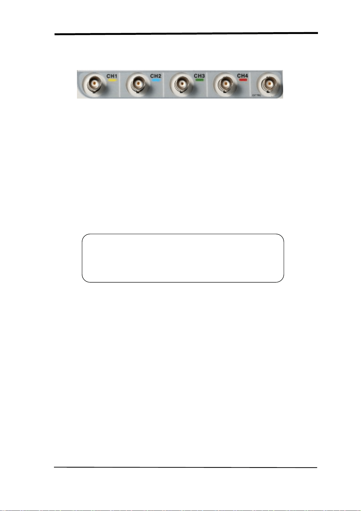
Picture 2-2
■ Channel Connector (CH1, CH2,CH3, CH4): Input connectors for waveforms
display.
■ EXT TRIG: Input connector for an external trigger source. Use the Trigger
Menu to select the “Ext” or “Ext/5” trigger source.
■ Probe Component: Voltage probe compensation output and ground. Use
to electrically match the probe to the oscilloscope input circuit.
Note:If you connect a voltage source to a ground terminal, you
may damage the oscilloscope or the circuit under test. To avoid
this, do not connect a voltage source to any ground terminals.
Loading ...
Loading ...
Loading ...