Loading ...
Loading ...
Loading ...
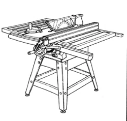
Ploughing and MoBding
Ploughing is grooving with the grain the long wa_/of the
workpiece, using the fence. Use featherboards and push
sticks as required.
Molding is shaping the wo_piece with the grain the _ong
way of the workpiece, using the fence. Use feather-
boards and push sticks as required.
Ploughing
_- ............................. ,!, i r,,
Molding Cutting
Instructions for operating the molding head are contained
in a booklet furnished with the molding head.
Always use the molding insert listed under recom-
mended accessories,
When using the molding head it will be necessary to
remove the blade guard and spreader. Use caution_ Use
miter gauge, fence, featherboards, or push sticks, etc.
as required.
WARNING: For your own safety, ak_ays replace the !
blade guard and spreader when you finished plough-
ing or moUding.
Molding
Adjustments ..................
WARNaNG: For your own safety, turn sw_tch "OFF" I
and remove plug from power source outlet before
l
making any adjustments.
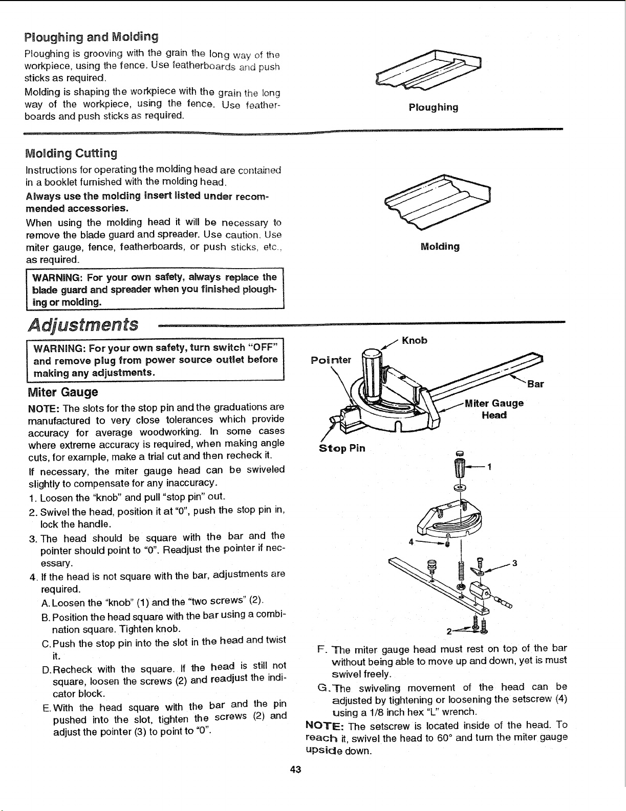
Miter Gauge
NOTE: The slots for the stop pin and the graduations are
manufactured to very close tolerances which provide
accuracy for average woodworking. Un some cases
where extreme accuracy is required, when making angle
cuts, for exarnple, make a trial cut and then recheck it.
If necessary, the miter gauge head can be swiveled
slightly to compensate for any inaccuracy.
1. Loosen the "knob" and pull "stop pin" out.
2. Swivel the head. position it at "0", push the stop pin in,
lockthe handle.
3. The head should be square with the bar and the
pointer should point to "0". Readjust the pointer if nec-
essary.
4. If the head is not square with the bar, adjustments are
required.
A. Loosen the "knob" (1) and the "two screws" (2).
B. Position the head square with the bar using a combi-
nation square. Tighten knob.
C. Push the stop pin into the slot in the head and twist
it.
D.Recheck with the square. If the head is still not
square, loosen the screws (2) and readjust the indi-
cator block.
E.With the head square with the bar and the pin
pushed into the slot, tighten the screws (2) and
adjust the pointer (3) to point to "0".
Pointer
\
\
Knob
Gauge
Head
Bar
Stop Pin
p-
F. The miter gauge head must rest on top of the bar
without being able to move up and down, yet is must
swivel freely.
G.-rhe swiveling movement of the head can be
adjusted by tightening or loosening the setscrew (4)
using a 1/8 inch hex "L" wrench.
NOTE: The setscrew is located inside of the head. To
reach it, swivel the head to 60 ° and turn the miter gauge
upside down.
43
Loading ...
Loading ...
Loading ...