Loading ...
Loading ...
Loading ...
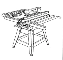
Assembly (continued)
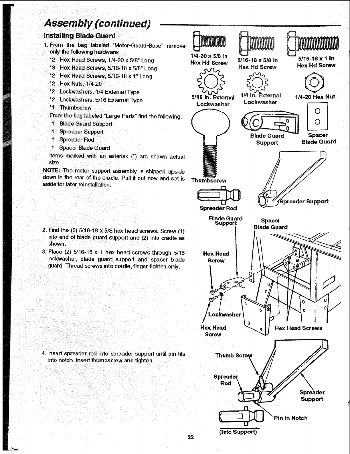
installing Blade Guard
1. From the bag labeled "MotoroGuard,,Base" remove
only the following hardware:
*2 Hex Head Screws. 1/4-20 x 5/8" Long
*3 Hex Head Screws, 5/16-18 x5/8" Long
*2 Hex Head Screws, 5/16-18 x 1" Long
*2 Hex Nuts, 1/4-20
*2 Lockwashers, 1/4 External Type
*2 Lockwashers, 5/16 External Type
"1 Thumbscrew
From the bag labeled "Large Pads" find the following:
1 Blade Guard Support
1 Spreader Support
1 Spreader Rod
1 Spacer Blade Guard
Items marked with an asterisk (*) are shown actual
size.
NOTE: The motor support assembly is shipped upside
down in the rear of the cradle. Pull it out now and set is
aside for later reinstallation.
1/4-20 x 5/8 In
Hex Hd Screw
Q
5/16 in. External
Lock"washer
5/16-18 x 5/8 in
Hex Hd Screw
1/4 in. E_ernal
Lockwasher
Blade Guard
Suppod
5/16-18 x I in
Hex Hd Screw
@
1/4-20 Hex Nut
Spacer
Blade Guard
Thumbscrew
Spreader Rod
2. Find the (3) 5/16-18 x 5/8 hex head screws. Screw (1)
into end of blade guard support and (2) into cradle as
shown.
3. Place (2) 5/16-18 x 1 hex head screws through 5/16
Iockwasher, blade guard support and spacer blade
guard. Thread screws into cradle, finger tighten only.
Blade Guard
Support
Hex Head
Screw
Spacer
Blade Guard
/
Hex Head
Screw
!J
Hex Head Screws
4. Insert spreader rod into spreader support until pin fits
into notch. Insert thumbscrew and tighten.
Thumb Scre_
Spreader
Rod
Suppod
in Notch
(Into Support)"
22
Loading ...
Loading ...
Loading ...