Loading ...
Loading ...
Loading ...
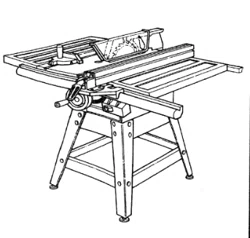
Assembly (continued)
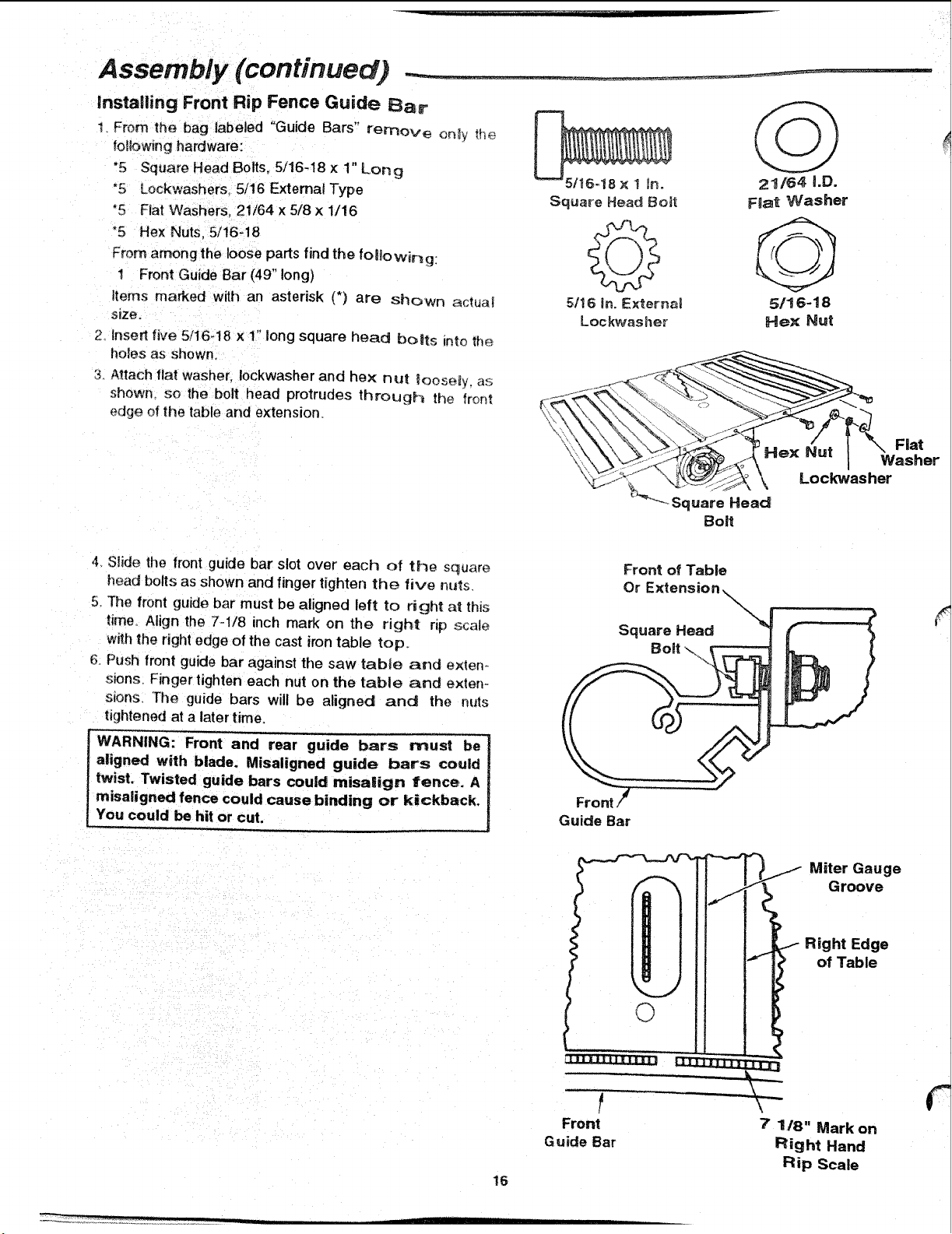
lnstafling Front Rip Fence Guide Bar
1_ From the bag labeled "Guide Bars" remove on_y _h_
following hardware:
"5 Square Head Bolts. 5/16-18 × 1" Long
*5 Lockwashers, 5/16 Externat Type
"5 Fiat Washers. 21/64 × 5/8 x 1/16
°5 Hex Nuts, 5/16-18
From among the loose parts find the folio wir_g
1 Front Guide Bar (49" long)
items marked with an asterisk (*) are Shown aclua_
size.
2_ Inset1 five 5/16-18 x 1" long square head bolts Into the
holes as shown
3. Attach flat washer, Iockwasher and hex nul loose_y, as;
shown so the bolt head protrudes through the front
edge of the table and extension.
21/64 i.D.
F_at Washer
5/!6-18
Hex Nut
.... Square Head
Boff
4 Slide the front guide bar slot over' each of the square
head bolts as shown and finger tighten the five nt_s
5. The front guide bar must be aligned left to right a_ this
time. Align the 7-1/8 inch mark on the r]gh! np scale
with the right edge of the cast iron table top.
Push front guide bar against the saw table and e×ten.,.
sions. Finger tighten each nut on the table and exten-
sions The guide bars will be aligned and the nuts
tightened at a later time.
_nt and rear guide bars must be
I aligned with blade. Misaligned guide bars could
I tW_w;stedg=;ide bars could misa|ign fence. A
t misaligned fence could cause binding or kickback.
oro,,.
Guide Bar
Front of Table
Or Ext
Square Head
Bolt \
!6
' Miter Gauge
Groove
i Right Edge
of Table
Front 7 118" Mark on
Guide Bar Right Hand
Rip Scale
Loading ...
Loading ...
Loading ...