Loading ...
Loading ...
Loading ...
Assembly (continued)
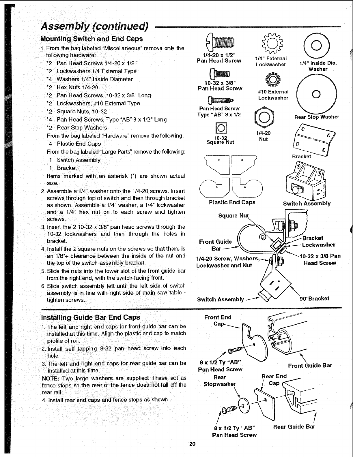
Mounting Switch and End Caps
1. Fmrn the bag labeled "Miscellaneous" remove only the
following hardware:
*2 Pan Head Screws 1/4-20 x 1/2"'
*2 Lockwashers 1/4 Extemal Type
*4 Washers 1/4" Inside Diameter
*2 Hex Nuts1/4-20
*2 Pan Head Screws, 10-32 x 3/8" Long
*2 Lockwashers, #10 External Type
*2 Square Nuts, 10-32
*4 Pan Head Screws, Type "AB" 8 x 1/2" Long
*2 Rear Stop Washers
From the bag labeled "Hardware" remove the following:
4 Plastic End Caps
From the bag labeled "Large Parts"remove the following:
1 Switch Assembly
1 Bracket
Items marked with an asterisk (*) are shown actual
size.
2. Assemble a 114" washer onto the 1/4-20 screws. Insert
screws through top of switch and then through bracket
as shown. Assemble a 1/4" washer, a 1/4" 10ckwasher
and a 1/4" hex nut on to each screw and tighten
screws.
114-20 x 1/2"
Pan Head Screw 114"External
Lockwasher 1/4" Inside Dia.
(_ O Washer
10-32 x 3/8" _, _
Pan Head Screw #10 External
Lockwasher
Pan Head Screw
Type "AB" 8 x 112
Rear Stop Washer
[_ 114-20
10-32 Nut
Square Nut
_\__ j) Bracket
PmasticEnd Caps Switch As,' ;mbly
Square Nut
3. Insert the 2 10-32 x 3/8" pan head screws through the
10-32 Iockwashers and then through the holes in
bracket.
4. Install the 2 square nuts on the screws so that there is
an 1/8"+ clearance between the inside of the nut and
the top of the switch assembly bracket.
5. Slide the nuts into the lower slot of the front guide bar
from the right end, with the switch facing front.
6, Slide switch assembly left until the left side of switch
assembly is in line with right side of main saw table -
tighten screws.
Front Guide
Bal
1/4-20 Screw, Washers,----_
Lockwasher and Nut
Switch Assembly
Bracket
x 3/8 Pan
Head Screw
90°Bracket
Installing Guide Bar End Caps
1. The left and right end caps for front guide bar can be
installed at thistime. Align the plastic end cap to match
profile of rail.
2. install self tapping 8-32 pan head screw into each
hole,
3. The left and right end caps for rear guide bar can be
installed at this time.
Front End _'j_._-_
8 x "AB" \
Front Guide Bar
Pan Head Screw
NOTE: Two large washers are supplied. These act as Rear Rear End
fence stops so the rear of the fence does not fall off the Stopwasher J Cap
rear rail. ____
4. Install rear end caps and fence stops as shown.
/
8 x 1/2 Ty "AB" Rear Guide Bar
Pan Head Screw
2O
Loading ...
Loading ...
Loading ...