Loading ...
Loading ...
Loading ...

CHAPTER 2 UNIX NETWORK CONFIGURATION (TCP/IP)
2-13
Certain BOOTP host software implementations will not respond to BOOTP
requests if you have not included a download filename in the configuration
file; if this is the case, simply create a null file on the host and specify the
name of this file and its path in the configuration file.
As with rarp, the print server will load its IP address from the BOOTP
server when the printer is powered on.
Configuring the IP Address with NCP or BRCONFIG
Users of DEC and Novell networks have additional alternatives for
configuring the IP addresses of Brother print servers by using the remote
console facility. On VMS systems, you will need to have DECNET running
in order to use the remote console.
The procedure is as follows:
a. Connect to the remote console. If you are using the remote console
with VMS or LTRIX, you will need to know the circuit ID (QNA-0
for Q-BUS systems, SVA-0 for DEC workstations, UNA-0 for
UNIBUS systems, BNA-0 for BI systems, and MNA-0 for XMI
systems; you can get the circuit ID by executing the VMS NCP
command SHOW KNOWN CIRCUITS) and the Ethernet address of
the print server (which you can get either from the label on the print
server or via the printer configuration page).
• To do this on a printer that has an LCD panel: take the printer off-
line by pressing the SEL button, press and hold down the SHIFT
button then press the UP arrow button until PRINT CONFIG is
displayed, press the SET button. The printer will then print out a
configuration sheet, the sheet labeled "Print Configuration"
contains all Print Server configuration information. Put the printer
back on-line again by pressing the SEL button.
• For internal Print Servers that are connected to a Brother printer
which do not have an LCD panel, refer to your printer user guide
for instructions on how to print out a configuration page.
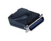
• Brother's external interfaces, which connect to the parallel
interface, have a black button recessed into the rear of the unit.
Press this button to print out a configuration sheet.
On VMS systems, the connection is made as shown in the following
example:
$ MCR NCP
NCP>CONNECT VIA QNA-0 PHY ADD 00-40-17-00-01-07
On ULTRIX systems, you would execute commands similar to the
following example:
# addnode BR -c qna-0 -h 00-40-17-00-01-07
# ccr BR
Loading ...
Loading ...
Loading ...
