Home
Bookmarks
Home
Binder
Binder CB-S 260 User Manual
Page 109
Binder CB-S 260 CO₂ incubator with hot air sterilization, series CB – 220-liter capacity
User Manual - Page 109
For CB-S 260.
PDF File Manual
,
119 pages
,
Read Online
|
Download pdf file
More photos
1. Safety
1.1 Personnel Qualification
1.2 Operating manual
1.3 Legal considerations
1.4 Structure of the safety instructions
1.4.1 Signal word panel
1.4.2 Safety alert symbol
1.4.3 Pictograms
1.4.4 Word message panel structure
1.5 Localization / position of safety labels at the chamber
1.6 Type plate
1.7 General safety instructions on installing and operating the chamber
1.8 Precautions when working with CO2 gas
1.9 Precautions when handling gas cylinders
1.10 Intended use
1.11 Foreseeable Misuse
1.12 Residual Risks
1.13 Operating instructions
1.14 Measures to prevent accidents
2. Chamber description
2.1 Chamber overview
2.2 Inner chamber
2.3 Connection panel on the rear of the chamber
2.4 Chamber doors
2.5 Instrument panel
3. Completeness of delivery, transportation, storage, and installation
3.1 Unpacking, and checking equipment and completeness of delivery
3.2 Guidelines for safe lifting and transportation
3.3 Storage
3.4 Location of installation and ambient conditions
4. Installation and connections
4.1 Shelves
4.2 CO2 sensor
4.2.1 Connecting the CO2 sensor
4.2.2 General notes
4.3 Water pan
4.4 Gas connection
4.4.1 Connecting the CO2 gas cylinder
4.4.2 Connecting the gas hose to the chamber rear
4.4.3 Gas cylinder connection kit (option)
4.5 Electrical connection
5. Functional overview of the RD4 chamber controller
5.1 Menu structure of the controller and access levels
5.2 Performance during and after power failures and shut down
6. Start up
6.1 Turning on the chamber
6.2 Preset factory parameters
6.3 Performance after turning on the chamber
6.4 Altitude of the installation site above sea level
7. Temperature and CO2 set-point entry
7.1 Temperature set-point entry
7.2 CO2 set-point entry
8. Placing samples in the incubator
9. Setting special controller functions
9.1 Idle mode
9.2 Deactivated CO2 control
10. Password
10.1 Password request
10.2 Assign and modify a password
10.2.1 Assign and modify the User password
10.2.2 Assign and modify the Admin password
11. Temperature safety devices
11.1 Over temperature protective device (class 1)
11.2 Overtemperature safety controller class 3.1
11.2.1 Setting the safety controller mode
11.2.2 Setting the safety controller value
11.2.3 Message and measures in the state of alarm
11.2.4 Function check
12. General controller settings
12.1 Selecting the controllerâs menu language
12.2 Selecting the temperature unit
12.3 Setting the current date
12.4 Setting the current time
12.5 Function âLanguage selection at restartâ
12.6 Setting the chamber address
12.7 Display brightness
13. Tolerance range settings
13.1 Setting the delay time for tolerance range alarm
13.2 Setting the temperature tolerance range
13.3 Setting the CO2 tolerance range
13.4 Setting the delay time for door open alarm
14. Chamber settings (for experienced users only)
14.1 Setting the humidity control
14.2 Setting the door heating offset
14.3 Adjusting the heating power â for BINDER Service only
15. Notification and alarm functions
15.1 Alarm messages
15.2 Information messages
15.3 Activating / deactivating the audible alarm (alarm buzzer)
15.4 Measures in case of alarm
15.4.1 Door open alarm
15.4.2 Safety controller temperature alarm
15.4.3 Temperature tolerance range alarm (overtemperature / too low temperature)
15.4.4 CO2 tolerance range alarm (CO2 over/under concentration)
15.4.5 CO2 pressure alarm
15.4.6 Power failure alarm
15.4.7 Alarms referring to temperature sensor failures
15.4.8 Alarms referring to CO2 sensor failure
15.4.9 Alarm on ineffective sterilization
15.5 Zero-voltage relay alarm output
16. Ethernet network settings
16.1 Showing the network settings
16.1.1 Showing the chamberâs MAC address
16.1.2 Showing the IP address
16.1.3 Showing the subnet mask
16.1.4 Showing the standard gateway
16.1.5 Showing the DNS server address
16.1.6 Showing the DNS chamber name
16.2 Changing the configuration of the network settings
16.2.1 Selecting the type of IP address assignment (automatic / manual)
16.2.2 Selecting the type of assignment of the DNS server address (automatic / manual)
16.2.3 Assigning the IP address
16.2.4 Setting the subnet mask
16.2.5 Setting the standard gateway
16.2.6 Assigning the DNS server address
17. Data recorder
17.1 Recorded data
17.2 Storage capacity
17.3 Setting the storage rate for the âDL1â recorder data
17.4 Deleting the data recorder
18. USB menu: Data transfer via USB interface
18.1 Connecting the USB stick
18.2 Import function
18.3 Export functions
18.4 Ongoing data transfer
18.5 Error during data transmission
18.6 Removing the USB stick
19. Reference measurements
19.1 CO2 reference measuring
19.1.1 Measuring the CO2 concentration indirectly via the pH of the cell medium
19.1.2 Measuring CO2 directly via chemical indicator tubes
19.1.3 Measuring CO2 directly with an electronic infrared measuring device
19.2 Temperature reference measurement
20. Options
20.1 Silicone access ports 30 mm / 1.18 in, closable with 2 silicone plugs (8012-0558 rear, 8012-0559 left, 8012-0560 right) (option)
20.2 Base on castors (option)
20.3 Flat stacking frame (option)
20.4 APT-COM⢠4 Multi Management Software (option)
20.5 Data logger kit (option)
20.6 Analog outputs for temperature and CO2 (option)
21. Avoiding microbial contamination
21.1 Cells and media
21.2 Laboratory conditions / equipment around the CO2 incubator
21.3 Working and behavior in the lab
21.4 Chamber design and equipment
21.5 Handling the CO2 incubator
22. Cleaning, decontamination / disinfection, and sterilization
22.1 Cleaning
22.2 Decontamination / chemical disinfection of the chamber
22.3 Disinfection of the CO2 sensor
23. Hot-air sterilization at 180 °C / 356 °F
23.1 Overview
23.2 Performing a hot-air sterilization
23.2.1 Preparations for hot-air sterilization
23.3 Starting and running the hot-air sterilization cycle
23.3.1 Starting sterilization
23.3.2 Performance during sterilization
23.3.3 Completing the entire sterilization cycle
23.4 Prematurely terminating the sterilization cycle â effects
23.4.1 Premature termination after less than 6 hours: Ineffective sterilization
23.4.2 Premature termination after more than 6 hours, i.e., during the cooling-down phase: successful sterilization
23.5 Prematurely terminating the sterilization cycle â procedure
23.5.1 Cancelling sterilization via the controller menu
23.5.2 Opening the outer door
23.5.3 Turning off the chamber
24. Maintenance, and service, troubleshooting, repair, testing
24.1 General information, personnel qualification
24.2 Maintenance intervals, service
24.3 Service Reminder
24.4 Gas inlet fine filter
24.5 Simple troubleshooting
24.5.1 General
24.5.2 Temperature
24.5.3 CO2
24.5.4 Humidity
24.5.5 Controller
24.5.6 Sterilization
24.6 Sending the chamber back to BINDER GmbH
25. Disposal
25.1 Disposal of the transport packing
25.1.1 Outer chamber packing
25.1.2 Packing inside the chamber, equipment
25.2 Decommissioning
25.3 Disposal of the chamber in the Federal Republic of Germany
25.4 Disposal of the chamber in the member states of the EU except for the Federal Republic of Germany
25.5 Disposal of the chamber in non-member states of the EU
26. Technical description
26.1 Factory calibration and adjustment
26.2 Over current protection
26.3 Definition of usable volume
26.4 CB-S / CB-S-UL technical data
26.5 Important conversion data for non-SI units
26.6 Conversion table for gas inlet pressures, bar â psi
26.7 Equipment and options (extract)
26.8 Options, accessories, and spare parts (extract)
26.9 Dimensions
27. Certificates and declarations of conformity
27.1 EU Declaration of Conformity
28. Product registration
29. Contamination clearance certificate
29.1 For chambers located outside the USA and Canada
29.2 For chambers in the USA and Canada
Page 109/119
Page 1
Page 2
Page 3
Page 4
Page 5
Page 6
Page 7
Page 8
Page 9
Page 10
Page 11
Page 12
Page 13
Page 14
Page 15
Page 16
Page 17
Page 18
Page 19
Page 20
Page 21
Page 22
Page 23
Page 24
Page 25
Page 26
Page 27
Page 28
Page 29
Page 30
Page 31
Page 32
Page 33
Page 34
Page 35
Page 36
Page 37
Page 38
Page 39
Page 40
Page 41
Page 42
Page 43
Page 44
Page 45
Page 46
Page 47
Page 48
Page 49
Page 50
Page 51
Page 52
Page 53
Page 54
Page 55
Page 56
Page 57
Page 58
Page 59
Page 60
Page 61
Page 62
Page 63
Page 64
Page 65
Page 66
Page 67
Page 68
Page 69
Page 70
Page 71
Page 72
Page 73
Page 74
Page 75
Page 76
Page 77
Page 78
Page 79
Page 80
Page 81
Page 82
Page 83
Page 84
Page 85
Page 86
Page 87
Page 88
Page 89
Page 90
Page 91
Page 92
Page 93
Page 94
Page 95
Page 96
Page 97
Page 98
Page 99
Page 100
Page 101
Page 102
Page 103
Page 104
Page 105
Page 106
Page 107
Page 108
Page 109
Page 110
Page 111
Page 112
Page 113
Page 114
Page 115
Page 116
Page 117
Page 118
Page 119
Contents
Table of Contents
Search
Previous
Next
Troubleshooting
Bookmarks
Loading ...
Loading ...
Loading ...
CB-S
/
CB-S-
UL
(
E7)
06/2020
page 109
/
11
9
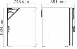
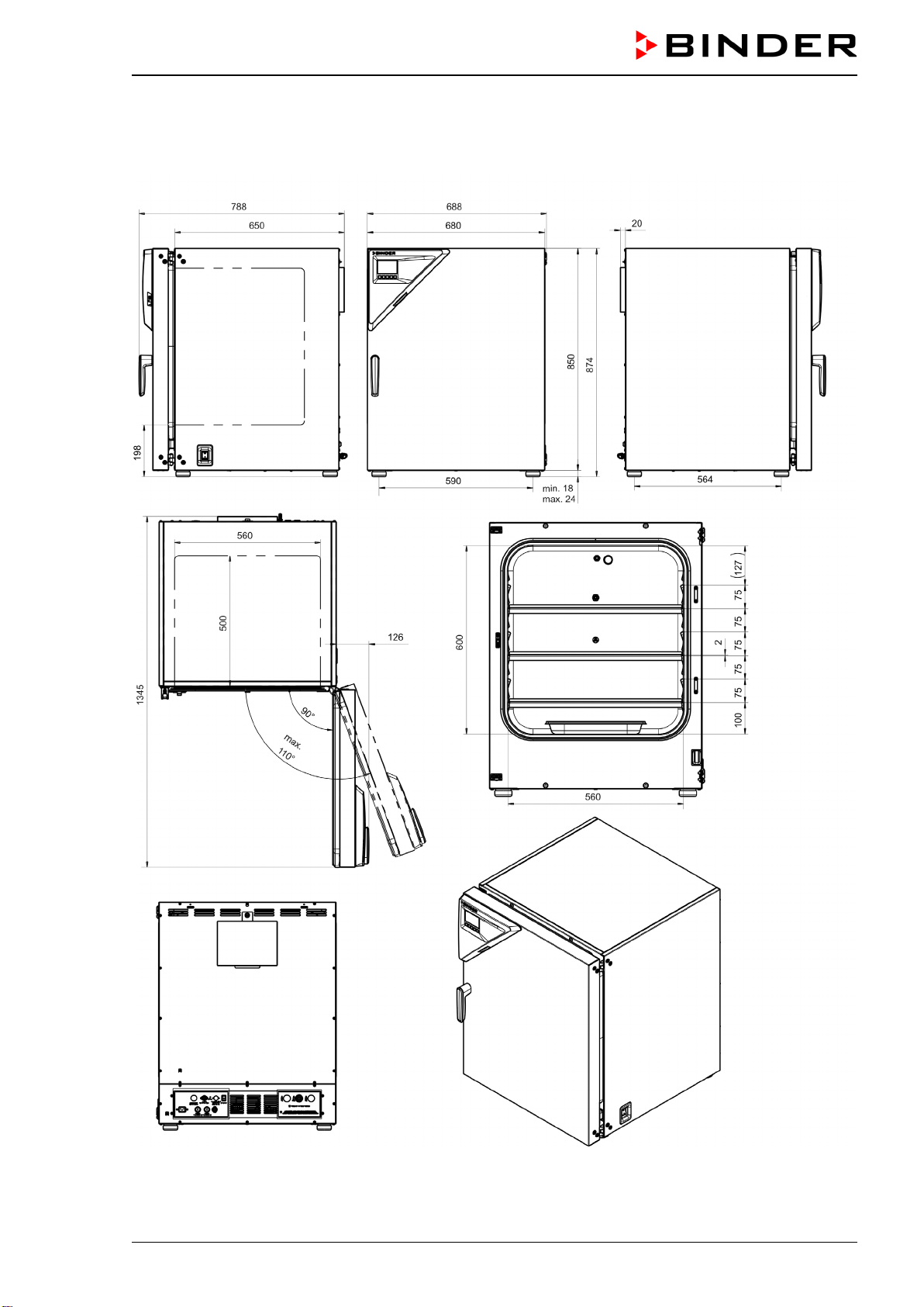
26.9
D
imensions
CB
-
S / CB
-S-
UL 170:
[Dim
ensions in mm
]
Loading ...
Loading ...
Loading ...
File type: PDF
File name: 32663186_cb-s-170.pdf
File size: 6.08 MB
File Language: English
Pages: 119
Author: Binder
File created: 2020-06-25
Published: 2021-08-19
Updated: 2023-05-22
Download File
Table of Contents
×
1. Safety
6
1.1 Personnel Qualification
6
1.2 Operating manual
6
1.3 Legal considerations
6
1.4 Structure of the safety instructions
7
1.4.1 Signal word panel
7
1.4.2 Safety alert symbol
7
1.4.3 Pictograms
8
1.4.4 Word message panel structure
8
1.5 Localization / position of safety labels at the chamber
9
1.6 Type plate
10
1.7 General safety instructions on installing and operating the chamber
11
1.8 Precautions when working with CO2 gas
13
1.9 Precautions when handling gas cylinders
13
1.10 Intended use
14
1.11 Foreseeable Misuse
15
1.12 Residual Risks
16
1.13 Operating instructions
17
1.14 Measures to prevent accidents
18
2. Chamber description
19
2.1 Chamber overview
20
2.2 Inner chamber
21
2.3 Connection panel on the rear of the chamber
22
2.4 Chamber doors
23
2.5 Instrument panel
23
3. Completeness of delivery, transportation, storage, and installation
24
3.1 Unpacking, and checking equipment and completeness of delivery
24
3.2 Guidelines for safe lifting and transportation
25
3.3 Storage
25
3.4 Location of installation and ambient conditions
25
4. Installation and connections
28
4.1 Shelves
28
4.2 CO2 sensor
28
4.2.1 Connecting the CO2 sensor
28
4.2.2 General notes
28
4.3 Water pan
29
4.4 Gas connection
30
4.4.1 Connecting the CO2 gas cylinder
31
4.4.2 Connecting the gas hose to the chamber rear
32
4.4.3 Gas cylinder connection kit (option)
33
4.5 Electrical connection
34
5. Functional overview of the RD4 chamber controller
35
5.1 Menu structure of the controller and access levels
36
5.2 Performance during and after power failures and shut down
37
6. Start up
37
6.1 Turning on the chamber
37
6.2 Preset factory parameters
38
6.3 Performance after turning on the chamber
38
6.4 Altitude of the installation site above sea level
39
7. Temperature and CO2 set-point entry
40
7.1 Temperature set-point entry
40
7.2 CO2 set-point entry
40
8. Placing samples in the incubator
41
9. Setting special controller functions
42
9.1 Idle mode
42
9.2 Deactivated CO2 control
43
10. Password
43
10.1 Password request
43
10.2 Assign and modify a password
44
10.2.1 Assign and modify the User password
44
10.2.2 Assign and modify the Admin password
44
11. Temperature safety devices
45
11.1 Over temperature protective device (class 1)
45
11.2 Overtemperature safety controller class 3.1
45
11.2.1 Setting the safety controller mode
46
11.2.2 Setting the safety controller value
46
11.2.3 Message and measures in the state of alarm
47
11.2.4 Function check
47
12. General controller settings
48
12.1 Selecting the controllerâs menu language
48
12.2 Selecting the temperature unit
48
12.3 Setting the current date
49
12.4 Setting the current time
50
12.5 Function âLanguage selection at restartâ
50
12.6 Setting the chamber address
51
12.7 Display brightness
51
13. Tolerance range settings
52
13.1 Setting the delay time for tolerance range alarm
52
13.2 Setting the temperature tolerance range
52
13.3 Setting the CO2 tolerance range
53
13.4 Setting the delay time for door open alarm
53
14. Chamber settings (for experienced users only)
54
14.1 Setting the humidity control
54
14.2 Setting the door heating offset
54
14.3 Adjusting the heating power â for BINDER Service only
55
15. Notification and alarm functions
55
15.1 Alarm messages
55
15.2 Information messages
57
15.3 Activating / deactivating the audible alarm (alarm buzzer)
58
15.4 Measures in case of alarm
58
15.4.1 Door open alarm
58
15.4.2 Safety controller temperature alarm
58
15.4.3 Temperature tolerance range alarm (overtemperature / too low temperature)
59
15.4.4 CO2 tolerance range alarm (CO2 over/under concentration)
60
15.4.5 CO2 pressure alarm
60
15.4.6 Power failure alarm
61
15.4.7 Alarms referring to temperature sensor failures
62
15.4.8 Alarms referring to CO2 sensor failure
63
15.4.9 Alarm on ineffective sterilization
63
15.5 Zero-voltage relay alarm output
64
16. Ethernet network settings
65
16.1 Showing the network settings
65
16.1.1 Showing the chamberâs MAC address
65
16.1.2 Showing the IP address
65
16.1.3 Showing the subnet mask
66
16.1.4 Showing the standard gateway
66
16.1.5 Showing the DNS server address
66
16.1.6 Showing the DNS chamber name
67
16.2 Changing the configuration of the network settings
67
16.2.1 Selecting the type of IP address assignment (automatic / manual)
67
16.2.2 Selecting the type of assignment of the DNS server address (automatic / manual)
68
16.2.3 Assigning the IP address
68
16.2.4 Setting the subnet mask
69
16.2.5 Setting the standard gateway
69
16.2.6 Assigning the DNS server address
70
17. Data recorder
70
17.1 Recorded data
70
17.2 Storage capacity
71
17.3 Setting the storage rate for the âDL1â recorder data
71
17.4 Deleting the data recorder
71
18. USB menu: Data transfer via USB interface
72
18.1 Connecting the USB stick
72
18.2 Import function
73
18.3 Export functions
73
18.4 Ongoing data transfer
74
18.5 Error during data transmission
74
18.6 Removing the USB stick
74
19. Reference measurements
75
19.1 CO2 reference measuring
75
19.1.1 Measuring the CO2 concentration indirectly via the pH of the cell medium
75
19.1.2 Measuring CO2 directly via chemical indicator tubes
76
19.1.3 Measuring CO2 directly with an electronic infrared measuring device
77
19.2 Temperature reference measurement
77
20. Options
77
20.1 Silicone access ports 30 mm / 1.18 in, closable with 2 silicone plugs (8012-0558 rear, 8012-0559 left, 8012-0560 right) (option)
77
20.2 Base on castors (option)
78
20.3 Flat stacking frame (option)
78
20.4 APT-COM⢠4 Multi Management Software (option)
78
20.5 Data logger kit (option)
78
20.6 Analog outputs for temperature and CO2 (option)
79
21. Avoiding microbial contamination
79
21.1 Cells and media
79
21.2 Laboratory conditions / equipment around the CO2 incubator
79
21.3 Working and behavior in the lab
80
21.4 Chamber design and equipment
80
21.5 Handling the CO2 incubator
81
22. Cleaning, decontamination / disinfection, and sterilization
82
22.1 Cleaning
83
22.2 Decontamination / chemical disinfection of the chamber
84
22.3 Disinfection of the CO2 sensor
85
23. Hot-air sterilization at 180 °C / 356 °F
86
23.1 Overview
86
23.2 Performing a hot-air sterilization
87
23.2.1 Preparations for hot-air sterilization
87
23.3 Starting and running the hot-air sterilization cycle
88
23.3.1 Starting sterilization
88
23.3.2 Performance during sterilization
89
23.3.3 Completing the entire sterilization cycle
89
23.4 Prematurely terminating the sterilization cycle â effects
90
23.4.1 Premature termination after less than 6 hours: Ineffective sterilization
90
23.4.2 Premature termination after more than 6 hours, i.e., during the cooling-down phase: successful sterilization
91
23.5 Prematurely terminating the sterilization cycle â procedure
91
23.5.1 Cancelling sterilization via the controller menu
91
23.5.2 Opening the outer door
92
23.5.3 Turning off the chamber
92
24. Maintenance, and service, troubleshooting, repair, testing
93
24.1 General information, personnel qualification
93
24.2 Maintenance intervals, service
94
24.3 Service Reminder
94
24.4 Gas inlet fine filter
95
24.5 Simple troubleshooting
95
24.5.1 General
95
24.5.2 Temperature
96
24.5.3 CO2
97
24.5.4 Humidity
98
24.5.5 Controller
98
24.5.6 Sterilization
98
24.6 Sending the chamber back to BINDER GmbH
99
25. Disposal
100
25.1 Disposal of the transport packing
100
25.1.1 Outer chamber packing
100
25.1.2 Packing inside the chamber, equipment
100
25.2 Decommissioning
101
25.3 Disposal of the chamber in the Federal Republic of Germany
101
25.4 Disposal of the chamber in the member states of the EU except for the Federal Republic of Germany
102
25.5 Disposal of the chamber in non-member states of the EU
103
26. Technical description
104
26.1 Factory calibration and adjustment
104
26.2 Over current protection
104
26.3 Definition of usable volume
104
26.4 CB-S / CB-S-UL technical data
105
26.5 Important conversion data for non-SI units
106
26.6 Conversion table for gas inlet pressures, bar â psi
107
26.7 Equipment and options (extract)
107
26.8 Options, accessories, and spare parts (extract)
108
26.9 Dimensions
109
27. Certificates and declarations of conformity
111
27.1 EU Declaration of Conformity
111
28. Product registration
113
29. Contamination clearance certificate
114
29.1 For chambers located outside the USA and Canada
114
29.2 For chambers in the USA and Canada
117
Search:
×
Search