
Issue 06/2020 Art. No. 7001-0402
Operating Manual
CB-S / CB-S-UL (E7)
CO
2
Incubator
with FPI-sensor system and RD4 controller
Model Model version Art. No.
CB-S 170 CBS170-230V 9040-0189, 9140-0189
CB-S 170-UL CBSUL170-120V 9040-0190, 9140-0190
CB-S 260 CBS260-230V 9040-0191, 9140-0191
CB-S 260-UL CBSUL260-120V 9040-0192, 9140-0192
BINDER GmbH
Address: Post office box 102, 78502 Tuttlingen, Germany Phone: +49 7462 2005 0
Fax: +49 7462 2005 100 Internet: http://www.binder-world.com
E-mail: info@binder-world.com Service Hotline: +49 7462 2005 555
Service Fax: +49 7462 2005 93 555 Service E-Mail: service@binder-world.com
Service Hotline USA: +1 866 885 9794 or +1 631 224 4340 x3
Service Hotline Asia Pacific: +852 390 705 04 or +852 390 705 03
Service Hotline Russia and CIS: +7 495 988 15 16

CB-S / CB-S-UL (E7) 06/2020 page 2/119
Contents
1. SAFETY .................................................................................................................. 6
1.1 Personnel Qualification ....................................................................................................................... 6
1.2 Operating manual ................................................................................................................................ 6
1.3 Legal considerations ........................................................................................................................... 6
1.4 Structure of the safety instructions ...................................................................................................... 7
1.4.1 Signal word panel ..................................................................................................................... 7
1.4.2 Safety alert symbol ................................................................................................................... 7
1.4.3 Pictograms ................................................................................................................................ 8
1.4.4 Word message panel structure ................................................................................................. 8
1.5 Localization / position of safety labels at the chamber ....................................................................... 9
1.6 Type plate.......................................................................................................................................... 10
1.7 General safety instructions on installing and operating the chamber ............................................... 11
1.8 Precautions when working with CO
2
gas .......................................................................................... 13
1.9 Precautions when handling gas cylinders ......................................................................................... 13
1.10 Intended use ..................................................................................................................................... 14
1.11 Foreseeable Misuse .......................................................................................................................... 15
1.12 Residual Risks .................................................................................................................................. 16
1.13 Operating instructions ....................................................................................................................... 17
1.14 Measures to prevent accidents ......................................................................................................... 18
2. CHAMBER DESCRIPTION .................................................................................. 19
2.1 Chamber overview ............................................................................................................................ 20
2.2 Inner chamber ................................................................................................................................... 21
2.3 Connection panel on the rear of the chamber................................................................................... 22
2.4 Chamber doors ................................................................................................................................. 23
2.5 Instrument panel ............................................................................................................................... 23
3. COMPLETENESS OF DELIVERY, TRANSPORTATION, STORAGE, AND
INSTALLATION .................................................................................................... 24
3.1 Unpacking, and checking equipment and completeness of delivery ................................................ 24
3.2 Guidelines for safe lifting and transportation ..................................................................................... 25
3.3 Storage .............................................................................................................................................. 25
3.4 Location of installation and ambient conditions ................................................................................ 25
4. INSTALLATION AND CONNECTIONS ............................................................... 28
4.1 Shelves .............................................................................................................................................. 28
4.2 CO
2
sensor ........................................................................................................................................ 28
4.2.1 Connecting the CO
2
sensor .................................................................................................... 28
4.2.2 General notes ......................................................................................................................... 28
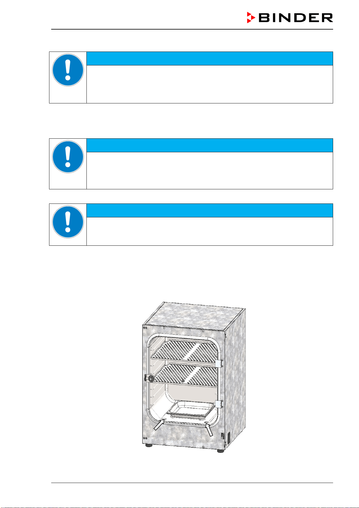
4.3 Water pan .......................................................................................................................................... 29
4.4 Gas connection ................................................................................................................................. 30
4.4.1 Connecting the CO
2
gas cylinder ............................................................................................ 31
4.4.2 Connecting the gas hose to the chamber rear ....................................................................... 32
4.4.3 Gas cylinder connection kit (option) ........................................................................................ 33
4.5 Electrical connection ......................................................................................................................... 34
5. FUNCTIONAL OVERVIEW OF THE RD4 CHAMBER CONTROLLER ............... 35
5.1 Menu structure of the controller and access levels ........................................................................... 36
5.2 Performance during and after power failures and shut down ........................................................... 37
6. START UP ............................................................................................................ 37
6.1 Turning on the chamber .................................................................................................................... 37
6.2 Preset factory parameters ................................................................................................................. 38
6.3 Performance after turning on the chamber ....................................................................................... 38
6.4 Altitude of the installation site above sea level ................................................................................. 39

CB-S / CB-S-UL (E7) 06/2020 page 3/119
7. TEMPERATURE AND CO
2
SET-POINT ENTRY ................................................. 40
7.1 Temperature set-point entry .............................................................................................................. 40
7.2 CO
2
set-point entry ............................................................................................................................ 40
8. PLACING SAMPLES IN THE INCUBATOR ........................................................ 41
9. SETTING SPECIAL CONTROLLER FUNCTIONS .............................................. 42
9.1 Idle mode........................................................................................................................................... 42
9.2 Deactivated CO
2
control .................................................................................................................... 43
10. PASSWORD ......................................................................................................... 43
10.1 Password request ............................................................................................................................. 43
10.2 Assign and modify a password ......................................................................................................... 44
10.2.1 Assign and modify the User password ................................................................................... 44
10.2.2 Assign and modify the Admin password ................................................................................. 44
11. TEMPERATURE SAFETY DEVICES ................................................................... 45
11.1 Over temperature protective device (class 1) ................................................................................... 45
11.2 Overtemperature safety controller class 3.1 ..................................................................................... 45
11.2.1 Setting the safety controller mode .......................................................................................... 46
11.2.2 Setting the safety controller value ........................................................................................... 46
11.2.3 Message and measures in the state of alarm ......................................................................... 47
11.2.4 Function check ........................................................................................................................ 47
12. GENERAL CONTROLLER SETTINGS ................................................................ 48
12.1 Selecting the controller’s menu language ......................................................................................... 48
12.2 Selecting the temperature unit .......................................................................................................... 48
12.3 Setting the current date ..................................................................................................................... 49
12.4 Setting the current time ..................................................................................................................... 50
12.5 Function “Language selection at restart” .......................................................................................... 50
12.6 Setting the chamber address ............................................................................................................ 51
12.7 Display brightness ............................................................................................................................. 51
13. TOLERANCE RANGE SETTINGS ....................................................................... 52
13.1 Setting the delay time for tolerance range alarm .............................................................................. 52
13.2 Setting the temperature tolerance range .......................................................................................... 52
13.3 Setting the CO
2
tolerance range ....................................................................................................... 53
13.4 Setting the delay time for door open alarm ....................................................................................... 53
14. CHAMBER SETTINGS (FOR EXPERIENCED USERS ONLY) ........................... 54
14.1 Setting the humidity control ............................................................................................................... 54
14.2 Setting the door heating offset .......................................................................................................... 54
14.3 Adjusting the heating power – for BINDER Service only .................................................................. 55
15. NOTIFICATION AND ALARM FUNCTIONS ........................................................ 55
15.1 Alarm messages ............................................................................................................................... 55
15.2 Information messages ....................................................................................................................... 57
15.3 Activating / deactivating the audible alarm (alarm buzzer) ............................................................... 58
15.4 Measures in case of alarm ................................................................................................................ 58
15.4.1 Door open alarm ..................................................................................................................... 58
15.4.2 Safety controller temperature alarm ....................................................................................... 58
15.4.3 Temperature tolerance range alarm (overtemperature / too low temperature) ...................... 59
15.4.4 CO
2
tolerance range alarm (CO
2
over/under concentration) .................................................. 60
15.4.5 CO
2
pressure alarm ................................................................................................................ 60
15.4.6 Power failure alarm ................................................................................................................. 61
15.4.7 Alarms referring to temperature sensor failures ..................................................................... 62
15.4.8 Alarms referring to CO
2
sensor failure .................................................................................... 63
15.4.9 Alarm on ineffective sterilization ............................................................................................. 63
15.5 Zero-voltage relay alarm output ........................................................................................................ 64

CB-S / CB-S-UL (E7) 06/2020 page 4/119
16. ETHERNET NETWORK SETTINGS .................................................................... 65
16.1 Showing the network settings ........................................................................................................... 65
16.1.1 Showing the chamber‘s MAC address .................................................................................... 65
16.1.2 Showing the IP address .......................................................................................................... 65
16.1.3 Showing the subnet mask ....................................................................................................... 66
16.1.4 Showing the standard gateway ............................................................................................... 66
16.1.5 Showing the DNS server address ........................................................................................... 66
16.1.6 Showing the DNS chamber name .......................................................................................... 67
16.2 Changing the configuration of the network settings .......................................................................... 67
16.2.1 Selecting the type of IP address assignment (automatic / manual) ....................................... 67
16.2.2 Selecting the type of assignment of the DNS server address (automatic / manual) .............. 68
16.2.3 Assigning the IP address ........................................................................................................ 68
16.2.4 Setting the subnet mask ......................................................................................................... 69
16.2.5 Setting the standard gateway ................................................................................................. 69
16.2.6 Assigning the DNS server address ......................................................................................... 70
17. DATA RECORDER .............................................................................................. 70
17.1 Recorded data ................................................................................................................................... 70
17.2 Storage capacity ............................................................................................................................... 71
17.3 Setting the storage rate for the “DL1” recorder data ......................................................................... 71
17.4 Deleting the data recorder................................................................................................................. 71
18. USB MENU: DATA TRANSFER VIA USB INTERFACE ..................................... 72
18.1 Connecting the USB stick ................................................................................................................. 72
18.2 Import function .................................................................................................................................. 73
18.3 Export functions ................................................................................................................................ 73
18.4 Ongoing data transfer ....................................................................................................................... 74
18.5 Error during data transmission .......................................................................................................... 74
18.6 Removing the USB stick ................................................................................................................... 74
19. REFERENCE MEASUREMENTS ........................................................................ 75
19.1 CO
2
reference measuring ................................................................................................................. 75
19.1.1 Measuring the CO
2
concentration indirectly via the pH of the cell medium ............................ 75
19.1.2 Measuring CO
2
directly via chemical indicator tubes.............................................................. 76
19.1.3 Measuring CO
2
directly with an electronic infrared measuring device ................................... 77
19.2 Temperature reference measurement .............................................................................................. 77
20. OPTIONS .............................................................................................................. 77
20.1 Silicone access ports 30 mm / 1.18 in, closable with 2 silicone plugs (8012-0558 rear, 8012-0559
left, 8012-0560 right) (option) ............................................................................................................ 77
20.2 Base on castors (option) ................................................................................................................... 78
20.3 Flat stacking frame (option)............................................................................................................... 78
20.4 APT-COM™ 4 Multi Management Software (option) ........................................................................ 78
20.5 Data logger kit (option) ...................................................................................................................... 78
20.6 Analog outputs for temperature and CO
2
(option) ............................................................................ 79
21. AVOIDING MICROBIAL CONTAMINATION........................................................ 79
21.1 Cells and media ................................................................................................................................ 79
21.2 Laboratory conditions / equipment around the CO
2
incubator .......................................................... 79
21.3 Working and behavior in the lab ....................................................................................................... 80
21.4 Chamber design and equipment ....................................................................................................... 80
21.5 Handling the CO
2
incubator .............................................................................................................. 81
22. CLEANING, DECONTAMINATION / DISINFECTION, AND STERILIZATION .... 82
22.1 Cleaning ............................................................................................................................................ 83
22.2 Decontamination / chemical disinfection of the chamber .................................................................. 84
22.3 Disinfection of the CO
2
sensor .......................................................................................................... 85

CB-S / CB-S-UL (E7) 06/2020 page 5/119
23. HOT-AIR STERILIZATION AT 180 °C / 356 °F .................................................... 86
23.1 Overview ........................................................................................................................................... 86
23.2 Performing a hot-air sterilization ....................................................................................................... 87
23.2.1 Preparations for hot-air sterilization ........................................................................................ 87
23.3 Starting and running the hot-air sterilization cycle ............................................................................ 88
23.3.1 Starting sterilization ................................................................................................................. 88
23.3.2 Performance during sterilization ............................................................................................. 89
23.3.3 Completing the entire sterilization cycle ................................................................................. 89
23.4 Prematurely terminating the sterilization cycle – effects ................................................................... 90
23.4.1 Premature termination after less than 6 hours: Ineffective sterilization .................................. 90
23.4.2 Premature termination after more than 6 hours, i.e., during the cooling-down phase:
successful sterilization ............................................................................................................ 91
23.5 Prematurely terminating the sterilization cycle – procedure ............................................................. 91
23.5.1 Cancelling sterilization via the controller menu ...................................................................... 91
23.5.2 Opening the outer door ........................................................................................................... 92
23.5.3 Turning off the chamber .......................................................................................................... 92
24. MAINTENANCE, AND SERVICE, TROUBLESHOOTING, REPAIR, TESTING .. 93
24.1 General information, personnel qualification..................................................................................... 93
24.2 Maintenance intervals, service .......................................................................................................... 94
24.3 Service Reminder .............................................................................................................................. 94
24.4 Gas inlet fine filter ............................................................................................................................. 95
24.5 Simple troubleshooting ...................................................................................................................... 95
24.5.1 General ................................................................................................................................... 95
24.5.2 Temperature ........................................................................................................................... 96
24.5.3 CO
2
......................................................................................................................................... 97
24.5.4 Humidity .................................................................................................................................. 98
24.5.5 Controller ................................................................................................................................ 98
24.5.6 Sterilization ............................................................................................................................. 98
24.6 Sending the chamber back to BINDER GmbH ................................................................................. 99
25. DISPOSAL.......................................................................................................... 100
25.1 Disposal of the transport packing .................................................................................................... 100
25.1.1 Outer chamber packing......................................................................................................... 100
25.1.2 Packing inside the chamber, equipment ............................................................................... 100
25.2 Decommissioning ............................................................................................................................ 101
25.3 Disposal of the chamber in the Federal Republic of Germany ....................................................... 101
25.4 Disposal of the chamber in the member states of the EU except for the Federal Republic of
Germany................................................................
.......................................................................... 102
25.5 Disposal of the chamber in non-member states of the EU ............................................................. 103
26. TECHNICAL DESCRIPTION .............................................................................. 104
26.1 Factory calibration and adjustment ................................................................................................. 104
26.2 Over current protection ................................................................................................................... 104
26.3 Definition of usable volume ............................................................................................................. 104
26.4 CB-S / CB-S-UL technical data ....................................................................................................... 105
26.5 Important conversion data for non-SI units ..................................................................................... 106
26.6 Conversion table for gas inlet pressures, bar – psi ......................................................................... 107
26.7 Equipment and options (extract) ..................................................................................................... 107
26.8 Options, accessories, and spare parts (extract) ............................................................................. 108
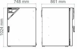
26.9 Dimensions...................................................................................................................................... 109
27. CERTIFICATES AND DECLARATIONS OF CONFORMITY ............................. 111
27.1 EU Declaration of Conformity.......................................................................................................... 111
28. PRODUCT REGISTRATION .............................................................................. 113
29. CONTAMINATION CLEARANCE CERTIFICATE ............................................. 114
29.1 For chambers located outside the USA and Canada ..................................................................... 114
29.2 For chambers in the USA and Canada ........................................................................................... 117
CB-S / CB-S-UL (E7) 06/2020 page 6/119
Dear Customer,
For the correct operation of the CO
2
incubator CB-S / CB-S-UL, it is important that you read this operating
manual completely and carefully and observe all instructions as indicated. Failure to read, understand
and follow the instructions may result in personal injury. It can also lead to damage to the chamber and/or
poor equipment performance.
1. Safety
1.1 Personnel Qualification
The chamber must only be installed, tested, and started up by personnel qualified for assembly, startup,
and operation of the chamber. Qualified personnel are persons whose professional education,
knowledge, experience and knowledge of relevant standards allow them to assess, carry out, and identify
any potential hazards in the work assigned to them. They must have been trained and instructed, and be
authorized, to work on the chamber.
The chamber should only be operated by laboratory personnel especially trained for this purpose and
familiar with all precautionary measures required for working in a laboratory. Observe the national regula-
tions on minimum age of laboratory personnel.
1.2 Operating manual
This operating manual is part of the components of delivery. Always keep it handy for reference in the
vicinity of the chamber. If selling the unit, hand over the operating manual to the purchaser.
To avoid injuries and damage observe the safety instructions of the operating manual. Failure to follow
instructions and safety precautions can lead to significant risks.
DANGER
Dangers due to failure to observe the instructions and safety precautions.
Serious injuries and chamber damage. Risk of death.
Observe the safety instructions in this Operating Manual.
Follow the operating procedures in this Operating Manual.
Carefully read the complete operating instructions of the chamber prior to installing and
using the chamber.
Keep the operating manual for future reference
Make sure that all persons who use the chamber and its associated work equipment have
read and understood the Operating Manual.
This Operating Manual is supplemented and updated as needed. Always use the most recent version of
the Operating Manual. When in doubt, call the BINDER Service Hotline for information on the up-to-
dateness and validity of this Operating Manual.
1.3 Legal considerations
This operating manual is for informational purposes only. It contains information for correct and safe in-
stalling, start-up, operation, decommissioning, cleaning and maintenance of the product. Note: the con-
tents and the product described are subject to change without notice.
Understanding and observing the instructions in this operating manual are prerequisites for hazard-free
use and safety during operation and maintenance. Images are to provide basic understanding. They may
deviate from the actual version of the chamber. The actual scope of delivery can, due to optional or spe-
cial design, or due to recent technical changes, deviate from the information and illustrations in these
instructions this operating manual.
CB-S / CB-S-UL (E7) 06/2020 page 7/119
In no event shall BINDER be held liable for any damages, direct or incidental arising out of or related to
the use of this manual.
This operating manual cannot cover all conceivable applications. If you would like additional information,
or if special problems arise that are not sufficiently addressed in this manual, please ask your dealer or
contact us directly, e.g. by phone at the number located on page one of this manual
Furthermore, we emphasize that the contents of this operating manual are not part of an earlier or exist-
ing agreement, description, or legal relationship, nor do they modify such a relationship. All obligations on
the part of BINDER derive from the respective purchase contract, which also contains the entire and ex-
clusively valid statement of warranty administration and the general terms and conditions, as well as the
legal regulations valid at the time the contract is concluded. The statements in this manual neither aug-
ment nor restrict the contractual warranty provisions.
1.4 Structure of the safety instructions
In this operating manual, the following safety definitions and symbols indicate dangerous situations in
accordance with the standards ISO 3864-2 and ANSI Z535.6.
1.4.1 Signal word panel
Depending on the seriousness and probability of serious consequences, potential dangers are identified
with a signal word, the corresponding safety color, and if appropriate, the safety alert symbol.
DANGER
Indicates an imminently hazardous situation that, if not avoided, will result in death or serious
(irreversible) injury.
WARNING
Indicates a potentially hazardous situation which, if not avoided, could result in death or serious
(irreversible) injury
CAUTION
Indicates a potentially hazardous situation which, if not avoided, may result in moderate or minor
(reversible) injury
NOTICE
Indicates a potentially hazardous situation which, if not avoided, may result in damage to the product
and/or its functions or of a property in its proximity.
1.4.2 Safety alert symbol
Use of the safety alert symbol indicates a risk of injury.
Observe all measures that are marked with the safety alert symbol in order to avoid death or
injury.
CB-S / CB-S-UL (E7) 06/2020 page 8/119
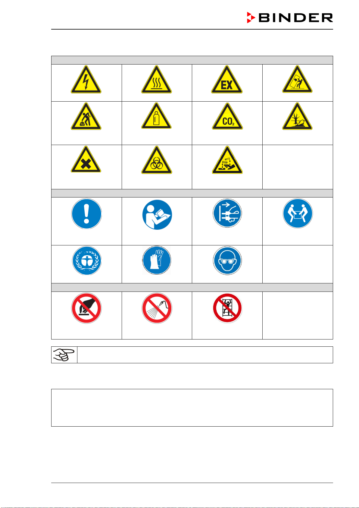
1.4.3 Pictograms
Warning signs
Electrical hazard
Hot surface
Explosive Atmosphere
Stability hazard
Lifting hazard
Gas cylinders
CO
2
suffocation and
poisoning hazard
Pollution Hazard
Harmful substances
Biohazard
Risk of corrosion and /
or chemical burns
Mandatory action signs
Mandatory regulation
Read operating
instructions
Disconnect the power
plug
Lift with several persons
Environment protection
Wear protective gloves
Wear safety goggles
Prohibition signs
Do NOT touch
Do NOT spray with
water
Do NOT climb
Information to be observed in order to ensure optimum function of the product.
1.4.4 Word message panel structure
Type / cause of hazard.
Possible consequences.
∅ Instruction on how to avoid the hazard: prohibition
Instruction on how to avoid the hazard: mandatory action
Observe all other notes and information not necessarily emphasized in the same way, in order to avoid
disruptions that could result in direct or indirect injury or property damage.
CB-S / CB-S-UL (E7) 06/2020 page 9/119
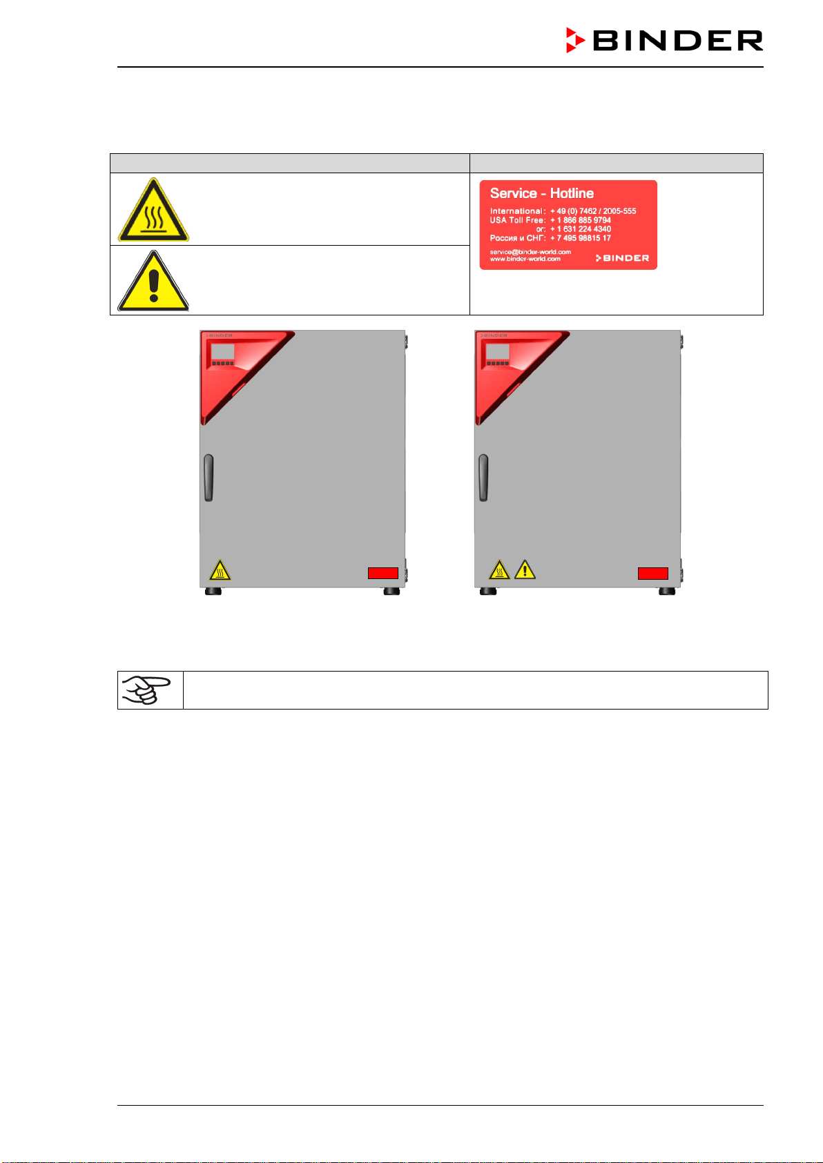
1.5 Localization / position of safety labels at the chamber
The following labels are located on the chamber:
Pictograms (Warning signs)
Service label
Hot surface
Risk of injury (UL chambers only).
Observe the safety instructions in the
operating manual.
Figure 1: Position of labels
on the CO
2
incubator CB-S
Figure 2: Position of labels
on the CO
2
incubator CB-S-UL
Keep safety labels complete and legible.
Replace safety labels that are no longer legible. Contact BINDER Service for these replacements.
CB-S / CB-S-UL (E7) 06/2020 page 10/119
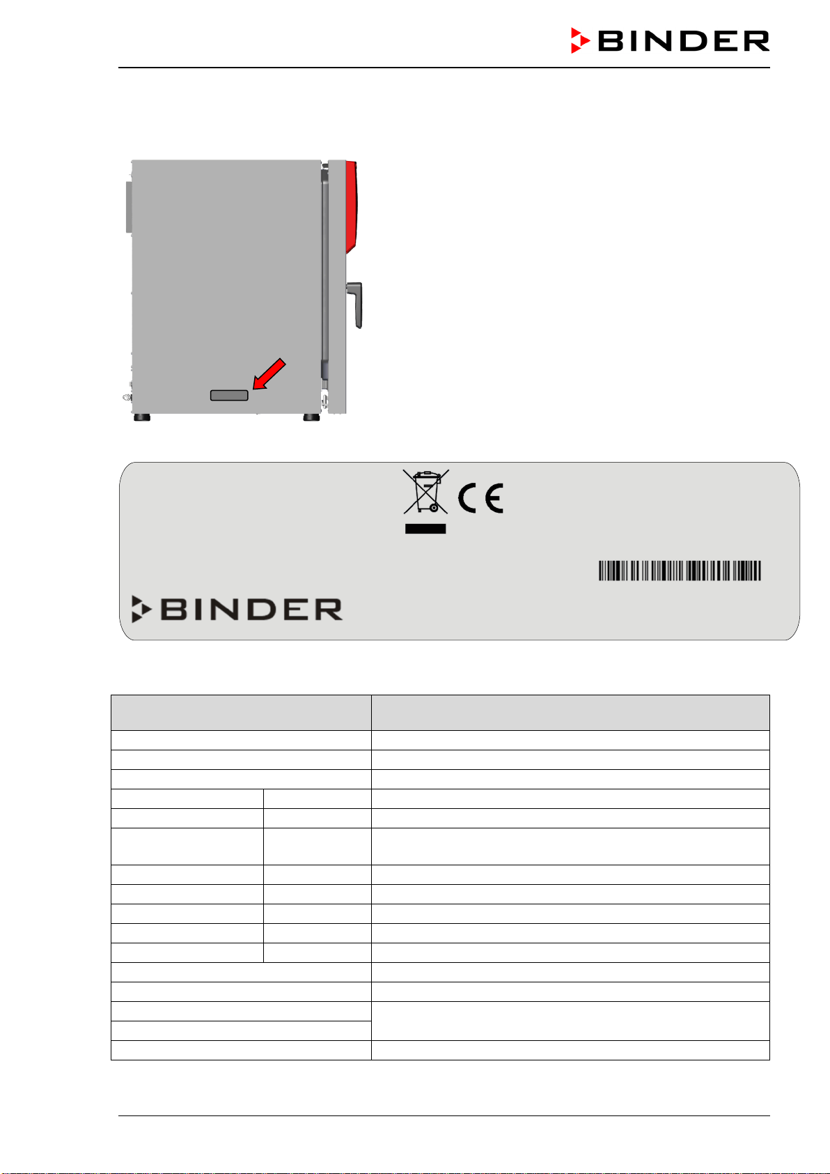
1.6 Type plate
Position of type plate: left chamber side (seen from front), at the bottom in the middle.
Figure 3: Position of type plate
Figure 4: Type plate (example CB-S 170 standard chamber, 9040-0189)
Indications of the type plate
(example)
Information
BINDER
Manufacturer: BINDER GmbH
CB-S 170
Model designation
CO2 Incubator
Device name: CO
2
Incubator
Serial No.
000000000000
Serial No. of the chamber
Built
2020
Year of construction
Nominal temperature
190 °C
374 °F
Nominal temperature
IP protection
20
Type of IP protection acc. to standard EN 60529
Temp. safety device
DIN 12880
Temperature safety device acc. to standard DIN 12880:2007
Class
3.1
Class of temperature safety device
Art. No.
9040-0189
Art. No. of the chamber
Project No.
---
Optional: Special application acc. to project no.
1,30 kW
Nominal power
6,1 A
Nominal current
200-230 V / 50 Hz
Nominal voltage range +/- 10%
at the indicated power frequency
200-230 V / 60 Hz
1 N ~
Current type
Nominal temp.
190 °C
1,30 kW / 6,1 A
374 °F
200-230 V / 50 Hz
IP protection
20
200-230 V / 60 Hz
Safety device
DIN 12880
1 N ~
Class
3.1
Art. No.
9040-0189
Project No.
Built
2020
CO2 Incubator
BINDER GmbH
Im Mittleren Ösch 5
78532 Tuttlingen / Germany
www.binder-world.com
CB-S 170
E7
Serial No. 00000000000000
Made in Germany
CB-S / CB-S-UL (E7) 06/2020 page 11/119
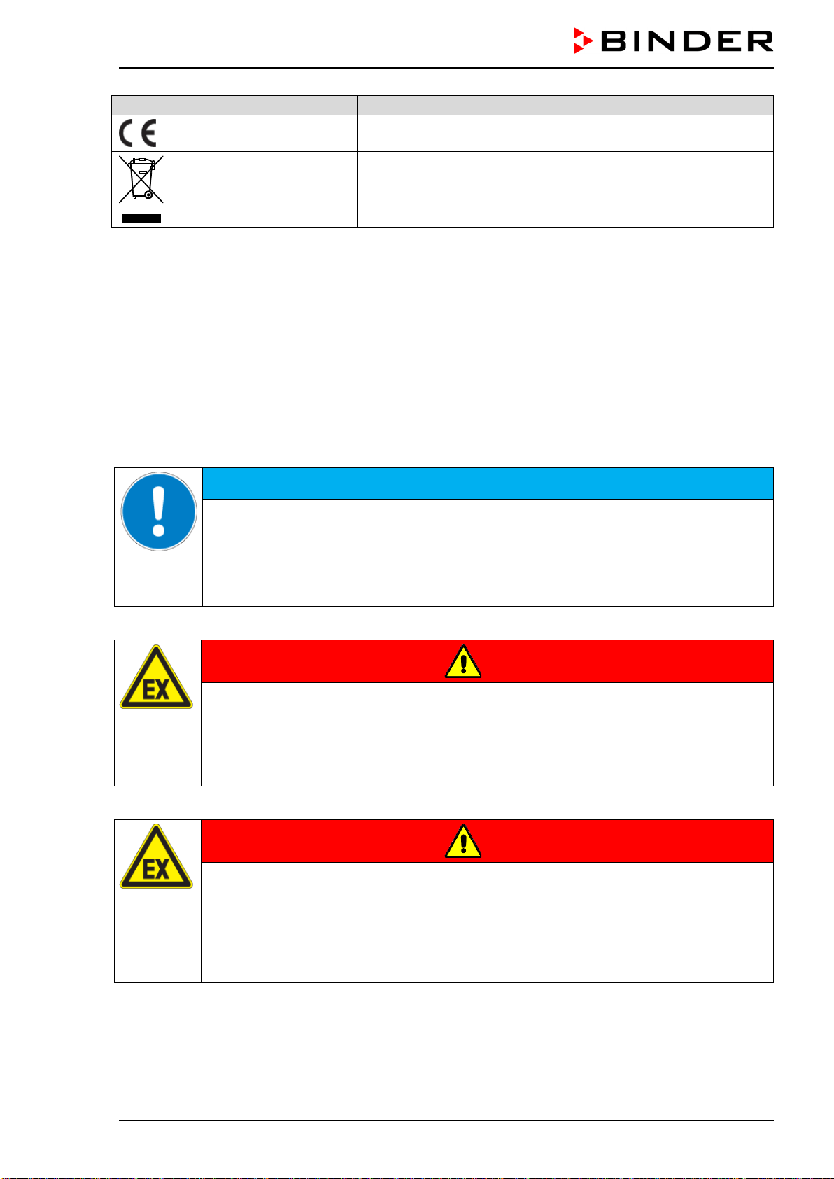
Symbol on the type plate
Information
CE conformity marking
Electrical and electronic equipment manufactured / placed on
the market in the EU after 13 August 2005 and to be disposed of
in a separate collection according to Directive 2012/19/EU on
waste electrical and electronic equipment (WEEE).
1.7 General safety instructions on installing and operating the chamber
With regard to operating the chamber and to the installation location, please observe the local and na-
tional regulations relevant for your country (for Germany: DGUV guidelines 213-850 on safe working in
laboratories, issued by the employers’ liability insurance association).
BINDER GmbH is only responsible for the safety features of the chamber provided skilled electricians or
qualified personnel authorized by BINDER perform all maintenance and repair, and if components relat-
ing to chamber safety are replaced in the event of failure with original spare parts.
To operate the chamber, use only original BINDER accessories or accessories from third-party suppliers
authorized by BINDER. The user is responsible for any risk caused by using unauthorized accessories.
NOTICE
Danger of overheating due to lack of ventilation.
Damage to the chamber.
∅ Do NOT install the chamber in unventilated recesses.
Ensure sufficient ventilation for dispersal of the heat.
Observe the prescribed minimum distances when installing the chamber (chap.3.4).
Do not install or operate the chamber in hazardous locations.
DANGER
Danger of explosion due to combustible dusts or explosive mixtures in the vicinity
of the chamber.
Serious injury or death from burns and / or explosion pressure.
∅ Do NOT operate the chamber in potentially explosive areas.
KEEP combustible dust or air-solvent mixtures AWAY from the chamber.
The chamber does not dispose of any measures of explosion protection.
DANGER
Danger of explosion due to introduction of flammable or explosive substances in
the chamber.
Serious injury or death from burns and / or explosion pressure.
∅ Do NOT introduce any substance into the chamber which is combustible or explosive at
working temperature.
∅ Do NOT introduce any combustible dust or air-solvent mixture in the inner chamber.
Any solvent contained in the charging material must not be explosive or inflammable. I.e., irrespective of
the solvent concentration in the steam room, NO explosive mixture with air must form. The temperature
inside the chamber must lie below the flash point or below the sublimation point of the charging material.
Familiarize yourself with the physical and chemical properties of the charging material, as well as the
contained moisture constituent and its behavior with the addition of heat energy and humidity.
CB-S / CB-S-UL (E7) 06/2020 page 12/119
Familiarize yourself with any potential health risks caused by the charging material, the contained mois-
ture constituent or by reaction products that may arise during the temperature process. Take adequate
measures to exclude such risks prior to putting the CO
2
incubator into operation.
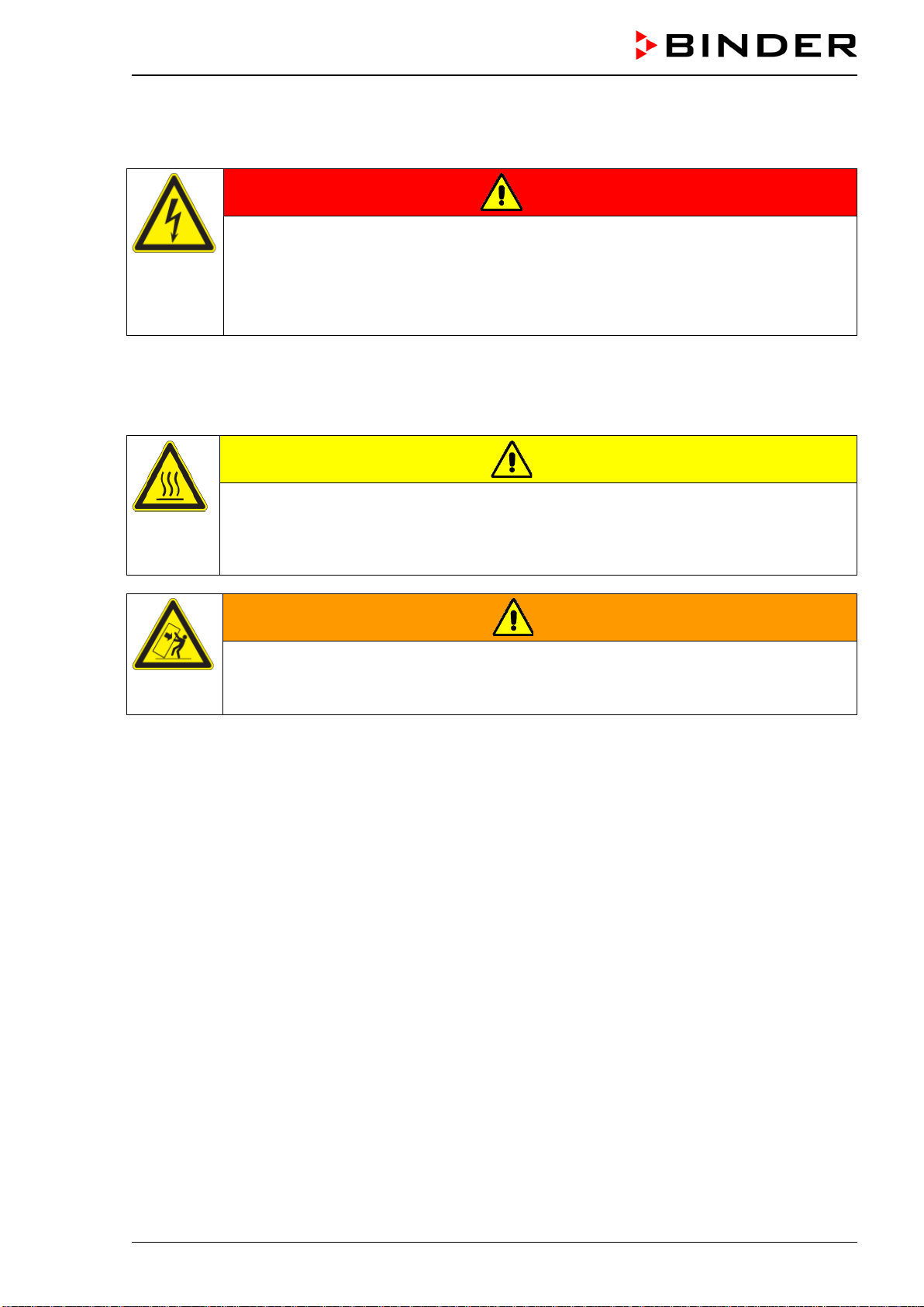
DANGER
Electrical hazard by water entering the chamber.
Deadly electric shock.
∅ The chamber must NOT become wet during operation, cleaning, or maintenance.
∅ Do NOT install the chamber in damp areas or in puddles.
Set up the chamber in a splash-proof manner.
The chambers were produced in accordance with VDE regulations and were routinely tested in accord-
ance to VDE 0411-1 (IEC 61010-1).
During and after a sterilization the temperature of the inner surfaces almost equals the set-point. The
glass door, the glass door handle, and the inner chamber will become hot during a sterilization.
CAUTION
Danger of burning by touching hot chamber parts during or after a sterilization.
Burns.
∅ Do NOT touch the glass door, the glass door handle, the inner surfaces, and door gas-
kets during or after a sterilization.
WARNING
Danger of injury and damages by the chamber tipping over.
Injuries and damage to the chamber and the charging material
∅ Do NOT load the chamber door with heavy objects while it is open.
CB-S / CB-S-UL (E7) 06/2020 page 13/119
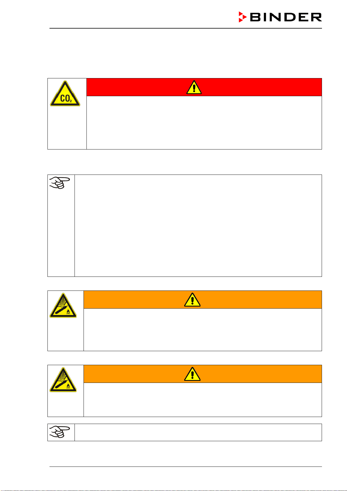
1.8 Precautions when working with CO
2
gas
Carbon dioxide (CO
2
) in high concentrations is hazardous to health. It is colorless and almost odorless
and therefore practically imperceptible. Vent out any CO
2
gas that may escape via good room ventilation
or a suitable connection to an exhaust system. We recommend installing a CO
2
warning system.
DANGER
Danger of suffocation and poisoning by high concentration of CO
2
(> 4 Vol.-%).
Death by suffocation.
∅ Do NOT set up chambers in non-ventilated recesses.
Ensure technical ventilation measures.
Observe the relevant regulations for handling CO
2
.
Close the CO
2
supply when decommissioning the chamber.
1.9 Precautions when handling gas cylinders
General information for safe handling of gas cylinders:
• Store and use gas cylinders only in well-ventilated locations.
• Open the gas cylinder valve slowly to avoid pressure surges
• Secure gas cylinders during storage and use against falling (chaining).
• Transport gas cylinders with a cylinder cart, do not carry, roll, or throw them.
•
Always close the valve even with apparently empty cylinders; screw on the cap when not in
use. Return gas cylinders with the valve closed.
• Do not open gas cylinders by force. Mark them when damaged
• Protect gas cylinders against fire, e.g. do not store together with flammable liquids
• Observe relevant regulations for dealing with gas cylinders.
Secure the gas cylinders against falling and other mechanical damage.
WARNING
Risk of injury through sudden release of the stored pressure energy when the valve
safety is torn off.
Injuries.
Secure gas cylinders against falling (chaining).
Transport gas cylinders with a cylinder cart.
The valve of the gas cylinder always must be closed before screwing on or unscrewing the gas hose.
WARNING
Risk of injury through sudden release of the stored pressure energy when opening
the cylinder valve of a not connected cylinder.
Injuries.
Close the gas cylinder valve before connecting or removing the gas hose.
After connecting the gas cylinder, check all gas connections for leaks (e.g. with leak spray or
diluted soap solution).
CB-S / CB-S-UL (E7) 06/2020 page 14/119
1.10 Intended use
Observing the instructions in this operating manual and conducting regular maintenance
work (chap. 24) is part of the intended use.
Any use of the chambers that does not comply with the requirements specified in this Operating
Manual shall be considered improper use.
Other applications than those described in this chapter are not approved.
Use
CO
2
incubators CB-S / CB-S-UL are suitable for the cultivation of mammal cells under typical conditions
of approx. 37 °C / 98.6 °F. The chambers permit setting defined pH conditions by common NaHCO
3
buff-
er systems of commercial cell media by keeping an exact CO
2
atmosphere inside. The chambers guaran-
tee high humidity inside to avoid osmolarity increasing caused by the evaporation of the cell media.
The chambers are suitable for exact conditioning of harmless materials.
Requirements for the chamber load
Any solvent any solvent must not be explosive and flammable. Components of the charging material must
NOT form an explosive mixture with air. The operating temperature must lie below the flash point or be-
low the sublimation point of the charging material. Any component of the charging material must NOT be
able to release toxic gases.
The charging material shall not contain any corrosive ingredients that may damage the machine compo-
nents made of stainless steel, aluminum, and copper. Such ingredients include in particular acids and
halides. Any corrosive damage caused by such ingredients is excluded from liability by BINDER GmbH.
The chamber does not dispose of any measures of explosion protection.
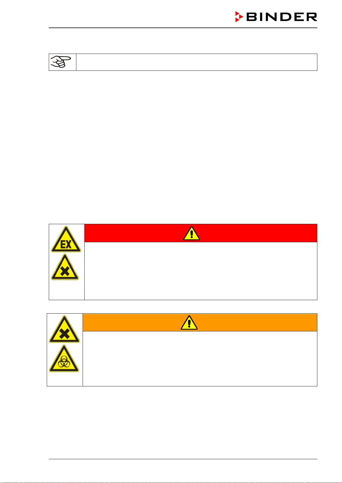
DANGER
Explosion or implosion hazard and danger of poisoning through the introduction of
unsuitable loading material.
Poisoning. Serious injury or death from burns and / or explosion pressure.
∅ Do NOT introduce any substance combustible or explosive at working temperature into
the chamber, in particular no energy sources such as batteries or lithium-ion batteries.
∅ NO explosive dust or air-solvent mixture in the inner chamber.
∅ Do NOT introduce any substance which could lead to release of toxic gases.
Contamination of the chamber by toxic, infectious or radioactive substances must be prevented
WARNING
Danger of intoxication and infection through contamination of the chamber with
toxic, infectious or radioactive substances.
Damages to health.
Protect the interior of the chamber from contamination by toxic, infectious or radioactive
substances.
Take suitable protective measures when introducing and removing toxic, infectious or
radioactive material
In case of foreseeable use of the device there is no risk for the user through the integration of the cham-
ber into systems or by special environmental or operating conditions in the sense of EN 61010-1:2010.
For this, the intended use of the chamber and all its connections must be observed.
CB-S / CB-S-UL (E7) 06/2020 page 15/119
Medical devices
The chambers are not classified as medical devices as defined by the Medical Device Directive
93/42/EEC.
Due to the special demands of the Medical Device Directive (MDD), these chambers are not
qualified for sterilization of medical devices as defined by the directive 93/42/EWG.
Personnel Requirements
Only trained personnel with knowledge of the Operating Manual can set up and install the chamber, start
it up, operate, clean, and take it out of operation. Service and repairs call for further technical require-
ments (e.g. electrical know-how), as well as knowledge of the service manual.
Installation site requirements
The chambers are designed for setting up inside a building (indoor use).
The requirements described in the Operating Manual for installation site and ambient conditions (Chap.
3.4) must be met.
WARNING: If customer should use a BINDER chamber running in non-supervised continu-
ous operation, we strongly recommend in case of inclusion of irrecoverable specimen or
samples to split such specimen or samples and store them in at least two chambers, if this is
feasible.
Relevant regulations for dealing with CO
2
and gas cylinders must be observed.
1.11 Foreseeable Misuse
Other applications than those described in chap. 1.10 are not approved.
This expressly includes the following misuses (the list is not exhaustive), which pose risks despite the
inherently safe construction and existing technical safety equipment:
• Non-observance of Operating Manual
• Non-observance of information and warnings on the chamber (e.g. control unit messages, safety iden-
tifiers, warning signals)
• Installation, startup, operation, maintenance and repair by untrained, insufficiently qualified, or unau-
thorized personnel
• Missed or delayed maintenance and testing
• Non-observance of traces of wear and tear
• Insertion of materials excluded or not permitted by this Operating Manual.
• Non-compliance with the admissible parameters for processing the respective material.
• Failure to comply with the relevant regulations for handling gas cylinders
• Failure to comply with the relevant regulations for handling CO
2
• Operation of the chamber without ventilation measures
• Installation, testing, service or repair in the presence of solvents
• Installation of replacement parts and use of accessories and operating resources not specified and
authorized by the manufacturer
• Installation, startup, operation, maintenance or repair of the chamber in absence of operating instruc-
tions
• Bypassing or changing protective systems, operation of the chamber without the designated protective
systems

CB-S / CB-S-UL (E7) 06/2020 page 16/119
• Non-observance of messages regarding cleaning and disinfection of the chamber.
• Spilling water or cleaning agent on the chamber, water penetrating into the chamber during operation,
cleaning or maintenance.
• Cleaning activity while chamber is turned on.
• Operation of the chamber with a damaged housing or damaged power cord.
• Continued operation of the chamber during an obvious malfunction
• Insertion of objects, particularly metallic objects, in louvers or other openings or slots on the chamber
• Human error (e.g. insufficient experience, qualification, stress, exhaustion, laziness)
To prevent these and other risks from incorrect operation, it is recommended the operator issue operating
instructions and standard operating procedures (SOPs).
1.12 Residual Risks
The unavoidable design features of a chamber, as well as its proper field of application, can also pose
risks, even during correct operation. These residual risks include hazards which, despite the inherently
safe design, existing technical protective equipment, safety precautions and supplementary protective
measures, cannot be ruled out.
Messages on the chamber and in the Operating Manual warn of residual risks. The consequences of
these residual risks and the measures required to prevent them are listed in the Operating Manual. More-
over, the operator must take measures to minimize hazards from unavoidable residual risks. This in-
cludes, in particular, issuing operating instructions.
The following list summarizes the hazards against which this Operating Manual and the Service Manual
warn, and specifies protective measures at the appropriate spots:
Unpacking, Transport, Installation
• Sliding or tilting the chamber
• Setup of the chamber in unauthorized areas
• Installation of a damaged chamber
• Installation of a chamber with damaged power cord
• Inappropriate site of installation
• Missing protective conductor connection
Normal operation
• Assembly errors
• Contact with hot surfaces on the housing
• Contact with hot surfaces in the interior and inside of doors
• Emission of non-ionizing radiation from electrical operating resources
• Contact with live parts in normal state
Cleaning and Decontamination
• Penetration of water into the chamber
• Inappropriate cleaning and decontamination agents
• Enclosure of persons in the interior
CB-S / CB-S-UL (E7) 06/2020 page 17/119
Malfunction and Damage
• Continued operation of the chamber during an obvious malfunction or outage of the heating or gas
systems
• Contact with live parts during error status
• Operation of a unit with damaged power cord
Maintenance
• Maintenance work on live parts.
• Execution of maintenance work by untrained/insufficiently qualified personnel
• Electrical safety analysis during annual maintenance not performed
Trouble-shooting and Repairs
• Non-observance of warning messages in the Service Manual
• Trouble-shooting of live parts without specified safety measures
• Absence of a plausibility check to rule out erroneous inscription of electrical components
• Performance of repair work by untrained/insufficiently qualified personnel
• Inappropriate repairs which do not meet the quality standard specified by BINDER
• Use of replacement parts other than BINDER original replacement parts
• Electrical safety analysis not performed after repairs
1.13 Operating instructions
Depending on the application and location of the chamber, it is recommended that the operator of the
chamber provides the relevant information for safe operation of the chamber in a set of operating instruc-
tions.
Keep these operating instructions with the chamber at all times in a place where they are
clearly visible. They must be comprehensible and written in the language of the employees.

CB-S / CB-S-UL (E7) 06/2020 page 18/119
1.14 Measures to prevent accidents
The manufacturer took the following measures to prevent dangers:
• Indications on the type plate
See operating manual chap. 1.6.
• Operating manual
An operating manual is available for each chamber.
• Overtemperature monitoring
The chamber is equipped with a temperature display, which can be read from outside.
The chamber is equipped with an additional safety controller (temperature safety device class 3.1 acc.
to DIN 12880:2007). Visual and audible (buzzer) signals indicate temperature exceeding.
• Safety, measurement, and control equipment
The safety, measuring, and control equipment is easily accessible.
• Electrostatic charge
The interior parts are grounded.
• Non-ionizing radiation
Non-ionizing radiation is not intentionally produced, but released only for technical reasons by electri-
cal equipment (e.g. power cables). The machine is equipped with no permanent magnets. If persons
with active implants (e.g. pacemakers, defibrillators) keep a safe distance (distance of field source to
implant) of 30 cm, an influence of these implants can be excluded with high probability.
• Protection against touchable surfaces
Tested according to EN ISO 13732-1:2008.
• Floors
See operating manual chap. 3.4 for correct installation
• Cleaning
See operating manual chap. 22.1.

CB-S / CB-S-UL (E7) 06/2020 page 19/119
2. Chamber description
The CO
2
incubators CB-S / CB-S-UL series were produced with great care using the latest tools for de-
velopment and production. They can be operated in a temperature range from 6 °C / 10.8 °F above ambi-
ent temperature up to +50 °C / 122°F and a CO
2
range of 0 vol.-% up to 20 vol.-%. The chambers are
equipped with a microprocessor controller for temperature and CO
2
levels and a digital display accurate
to one-tenth of a degree resp. 0.1 vol.-%. They are available in different voltages.
Material: The inner chamber, the pre-heating chamber and the inside of the doors are all made of stain-
less steel V2A (German material no. 1.4301, US equivalent AISI 304). The inner surfaces are smooth and
therefore easy to clean. The inner chamber is deep-drawn from one piece, polished (suitable for pharma-
ceutical applications) and has no welds or inaccessible corners. The hinges and the seal of the inner
glass door are glued from the outside to aid cleaning of the inner chamber. When operating the chamber
at high temperatures (sterilization), the impact of the oxygen in the air may cause discoloration of the
metallic surfaces (yellowish-brown or blue) by natural oxidation processes. These colorations are harm-
less and will in no way impair the function or quality of the chamber.
The perforated shelves are also made of stainless steel (German material no. 1.4016, US equivalent AISI
430). You can insert a maximum of 6 (CB-S / CB-S-UL 170) bzw. 8 (CB-S / CB-S-UL 260) shelves.
The housing is RAL 7035 powder-coated. All corners and edges are also completely coated. The stand-
ard chamber door is hinged right. The chamber is optionally available with the door hinged left.
Sterilization: The heating system of the chamber permits hot-air auto-sterilization at 190 °C / 374 °F.
Thus, a temperature of at least 180 °C / 356 °F is maintained on all internal surfaces, resulting in steriliza-
tion of the entire inner chamber.
Safety: Thanks to the standard safety device (class 3.1 according to DIN 12880:2007), the set tempera-
ture is maintained in case of failure.
An error diagnostics system monitors the chamber functions and generates audible and visual warning
and alarm messages. The door is monitored for being closed.
The controller provides access control by combining password protection with different authorization lev-
els.
CO
2
system: A highly precise, drift-free CO
2
infrared measuring system in combination with the perma-
nent mixture of CO
2
gas through a special proprietary gas mixing head developed by BINDER allows
precise and constant CO
2
concentrations for long periods. This creates optimum growth conditions for
cultures. The gas enters the chamber via a fine filter (aseptic filter) with a high filtration efficiency that also
filters the smallest particles.
The CO
2
sensor can be removed from the inner chamber by hand and cleaned with suitable detergents if
needed.
Fast reaction times, maximum accuracy and selectivity characterize the CO
2
measuring procedure of the
chamber. The accuracy of the CO
2
measuring system is based on an infrared measuring cell with NDIR
(non-dispersive infrared) sensor, which continuously regulates to a reference value. Therefore, disturb-
ance variables and aging phenomena in the measuring system are almost completely eliminated, so that
this measuring system, in contrast to other measuring procedures, remains practically drift-free between
calibrations and is entirely selective for CO
2
.
The CO
2
measuring cell contains a measuring section inside, in which the absorption of infrared light
depends on the number of CO
2
molecules in the beam path. This number of CO
2
molecules changes with
the ambient pressure in relation to a constant volume. The distances between the molecules are conse-
quently pressure-dependent. The collision frequency of the IR-beam with CO
2
molecules increases there-
fore by increasing pressure. For this reason, the ambient pressure must be compensated in order to cor-
rect the display reading of the CO
2
concentration in vol.-%. This is achieved by entering the altitude of the
site above the sea (chap. 6.4).
Controller: The efficient RD4 chamber controller is equipped with a multitude of operating functions, in
addition to recorder and alarm functions. Set-point entry is easily accomplished accurate to one-tenth of a
degree resp. 0.1 vol.-% directly via the chamber controller and is also possible directly with a computer
via Intranet in connection with the APT-COM™ 4 Multi Management Software (option, chap. 20.4). The
controller provides password protection for the setting menus. An error diagnostics system generates
audible and visual alarm messages.
CB-S / CB-S-UL (E7) 06/2020 page 20/119
Data monitoring and recording: The chamber is regularly equipped with a zero-voltage relay alarm
output (chap. 15.5) and optionally with analog outputs (chap. 20.6) for integration into customer systems.
The chamber is regularly equipped with an Ethernet interface for computer communication, enabling
monitoring via a network. The BINDER APT-COM™ 4 Multi Management Software (option, chap. 20.4)
permits networking of up to 100 chambers and connection to a computer, as well as recording and repre-
senting temperature and CO
2
data.
A data logger independent from the chamber controller (option, chap. 20.5) serves to independently rec-
ord the temperature values, data given out in compliance with FDA guideline 21 CFR part 11.
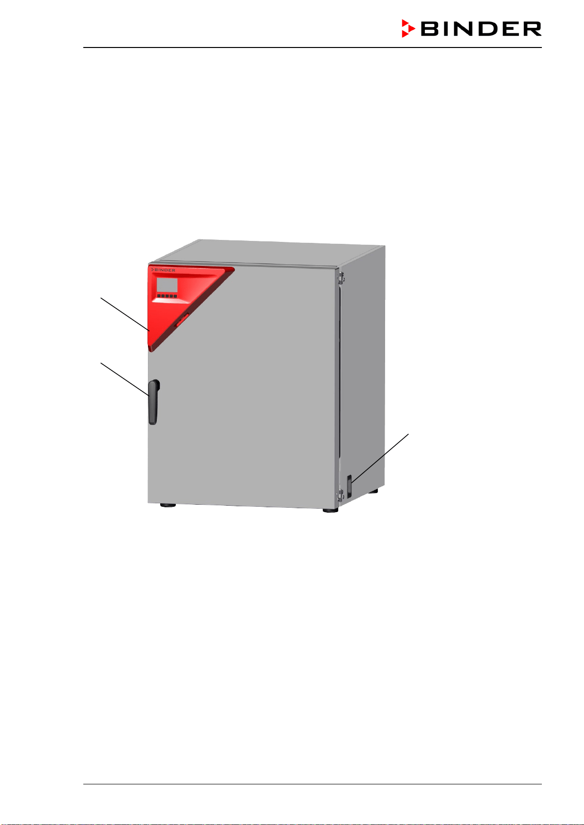
2.1 Chamber overview
Figure 5: CO
2
incubator CB-S / CB-S-UL (example CB-S 170), closed
(1) Triangle instrument panel with RD4 controller for temperature and CO
2
(2) Door handle
(3) Main power switch
(2)
(3)
(1)
CB-S / CB-S-UL (E7) 06/2020 page 21/119
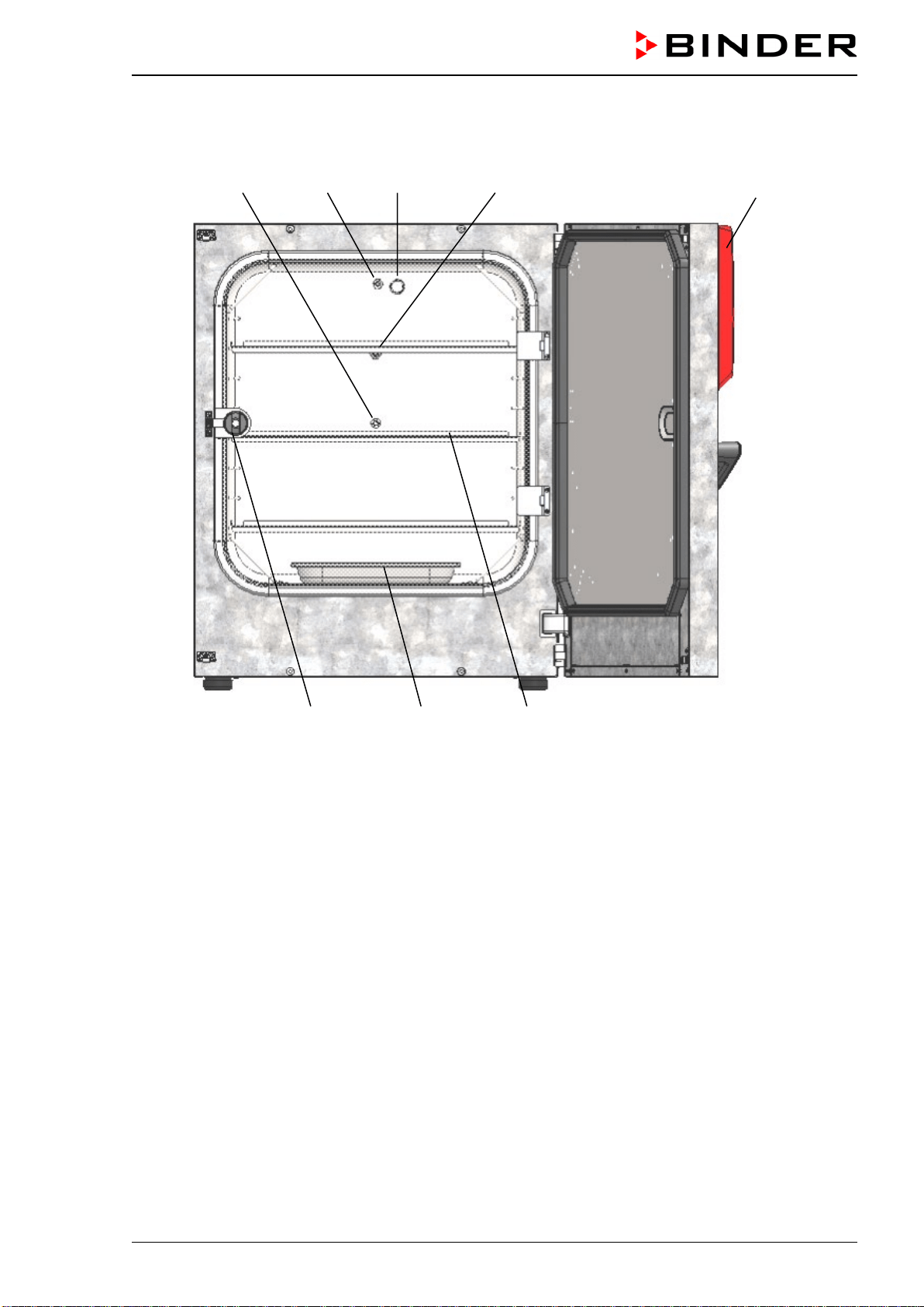
2.2 Inner chamber
Figure 6: CO
2
incubator CB-S / CB-S-UL (example CB-S 170), outer door open
(1) Triangle instrument panel with RD4 controller for temperature and CO
2
(4) Glass door handle
(5) Water pan
(6) Shelves
(7) (not used)
(8) Pt 100 temperature sensor
(9) CO
2
sensor
(10) Gas mixing head for CO
2
(11) Silicone measuring port in the glass door
(11) (10) (9) (8) (1)
(4) (5) (6)
CB-S / CB-S-UL (E7) 06/2020 page 22/119
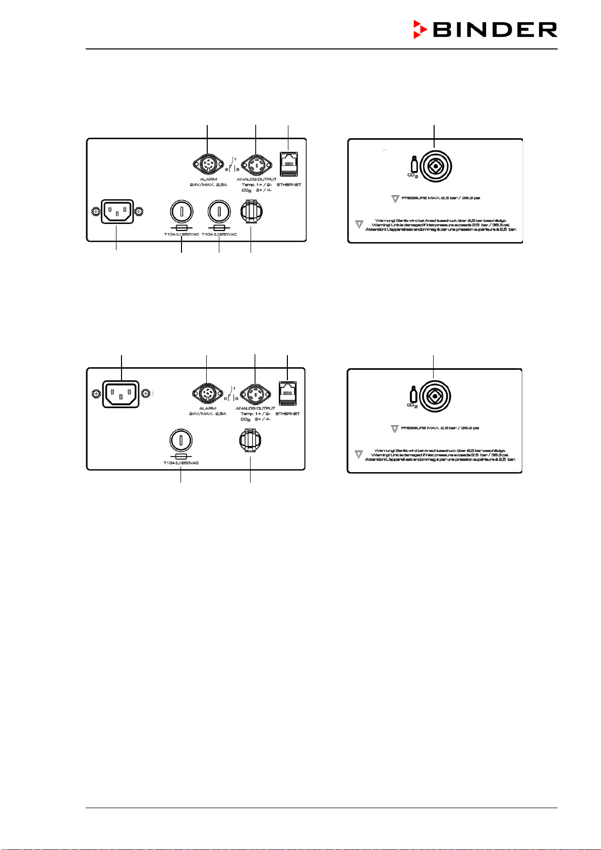
2.3 Connection panel on the rear of the chamber
(13) (14) (15) (18)
(12a) (16a) (16a) (17)
Figure 7: Rear control panel C with options
(12b) (13) (14) (15) (18)
(16b) (17)
Figure 8: Rear control panel C-UL with options
(12a) Socket for IEC connector plug / power cable 230 V AC for C
(12b) Socket for IEC connector plug / power cable 100-120 V AC for C-UL
(13) DIN-socket for zero-voltage relay alarm outputs
(14) DIN socket for analog outputs 4-20 mA (available by BINDER INDIVUDUAL Customized Solutions)
(15) Ethernet interface for computer communication
(16a) Miniature fuse T10 A (L) 250 V AC for C
(16b) Miniature fuse T12,5 A (L) 250 V AV for C-UL
(17) Strain relief for power cable
(18) Quick acting closure socket for CO
2
CB-S / CB-S-UL (E7) 06/2020 page 23/119
2.4 Chamber doors
The outer chamber door is equipped with a heater on its inner side. The door must be closed while the
chamber is operating normally in order to ensure stable climatic conditions in the inner chamber.
An additional glass door enables viewing of the samples without disturbing the temperature in the interior
and contaminating the samples sealing the interior of the chamber.
When the outer door is open, the CO
2
intake valve automatically closes.
Delay time for the temperature and CO
2
tolerance range alarm :
After closing the outer door, the tolerance range alarm is turned off for a programmable delay
time. This prevents alarms being constantly triggered during the unstable operating phase
after opening the outer door.
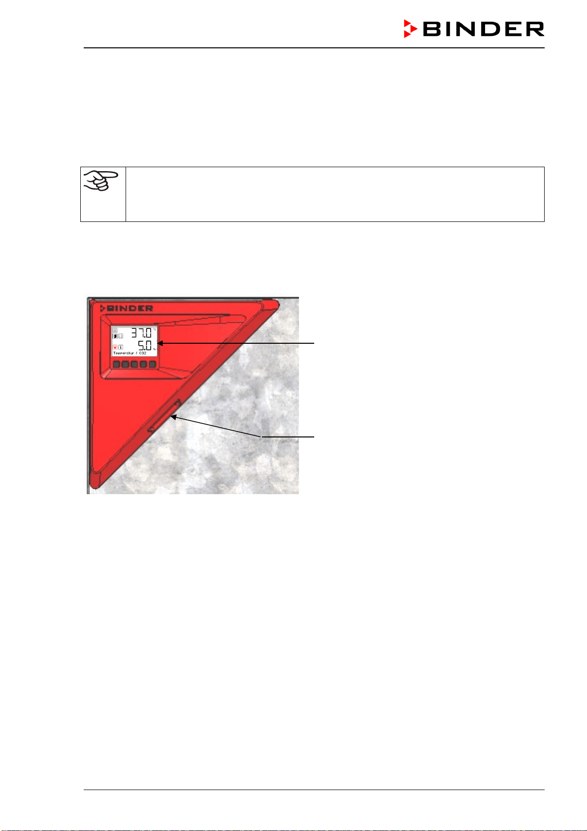
2.5 Instrument panel
RD4 controller display
USB interface
Figure 9: Instrument panel with RD4 controller and USB interface
CB-S / CB-S-UL (E7) 06/2020 page 24/119
3. Completeness of delivery, transportation, storage, and installa-
tion
3.1 Unpacking, and checking equipment and completeness of delivery
After unpacking, please check the chamber and its optional accessories, if any, based on the delivery
receipt for completeness and for transportation damage. Inform the carrier immediately if transportation
damage has occurred.
The final tests of the manufacturer may have caused traces of the shelves on the inner surfaces. This has
no impact on the function and performance of the chamber.
Please remove any transportation protection devices and adhesives in/on the chamber and on the doors
and remove the operating manuals and accessory equipment.
For transport purpose, a silica gel bag for drying purpose was added. Do not eat! Do not open the silica
gel bag and dispose of it with normal waste.
Remove any protective lamination sheet on the inner metal surfaces prior to commissioning.
CAUTION
Risk of injury and damages by lifting heavy loads and by sliding or
tilting of the chamber due to improper lifting.
Injuries, damage to the chamber.
∅ Do NOT lift or transport the chamber using the door handle or the door.
Lift the chamber from the pallet at the four lowe
r corners with the aid of
four people.
If you need to return the chamber, please use the original packing and observe the guidelines for safe
lifting and transportation (chap. 3.2).
For disposal of the transport packing, see chap. 25.1.
Note on second-hand chambers (Ex-Demo-Units):
Second-hand chambers are chambers that were used for a short time for tests or exhibitions. They are
thoroughly tested before resale. BINDER ensures that the chamber is technically sound and will work
flawlessly.
Second-hand chambers are marked with a sticker on the chamber door. Please remove the sticker before
commissioning the chamber.
CB-S / CB-S-UL (E7) 06/2020 page 25/119
3.2 Guidelines for safe lifting and transportation
After operation, please observe the guidelines for temporarily decommissioning the chamber (chap. 25.2).
Empty the water pan before moving the incubator. In case of any spilling of the contents, shut down the
incubator and dry it out carefully and completely
CAUTION
Risk of injury and damages by lifting heavy loads and by sliding or tilting of the
chamber due to improper transportation.
Injuries, damage to the chamber.
Transport the chamber in its original packaging only.
For moving or shipping, secure the chamber with transport straps.
∅ Do NOT lift or transport the chamber using the door handle or the door.
Lift the chamber at the four lower corners with the aid of 4 people and place it on a
rolling pallet.
Move the chamber to the desir
ed location and lift it from the rolling pallet with the aid of
four people.
• Permissible ambient temperature range for transport: -10 °C / 14°F to +60 °C / 140°F.
You can order transport packing and rolling pallets for transportation purposes from BINDER Service.
3.3 Storage
Intermediate storage of the chamber is possible in a closed and dry room. Observe the guidelines for
temporary decommissioning (chap. 25.2).
• Permissible ambient temperature range for storage: -10 °C / 14°F to +60 °C / 140°F.
• Permissible ambient humidity: max. 70% r.h., non-condensing
When after storage in a cold location you transfer the chamber to its warmer installation site, condensa-
tion may form in the inner chamber, on the housing or in the sensor compartment of the CO
2
measure-
ment. Before start-up, wait at least one hour until the CO
2
incubator has attained ambient temperature
and is completely dry.
3.4 Location of installation and ambient conditions
Notes on the location of installation
Set up the chamber on a flat, even surface, free from vibration and in a well-ventilated, dry location. The
chambers are designed for setting up inside a building (indoor use).
Freestanding chambers are suitable for installation on tables or on the optionally available stand. Note:
The site of installation must be capable of supporting the chamber’s weight (see technical data, chap.
26.4).
Align the chamber using a spirit level to ensure even covering of the cell-cultures with the medium. For
this purpose, manually adjust the four incubator feet.
In order to avoid contamination, never place the chamber directly on the floor.
CB-S / CB-S-UL (E7) 06/2020 page 26/119
NOTICE
Danger of overheating due to lack of ventilation.
Damage to the chamber.
∅ Do NOT install the chamber in unventilated recesses.
Ensure sufficient ventilation for dispersal of the heat.
Observe the prescribed minimum distances when installing the chamber.
Do not install or operate the chamber in potentially explosive areas.
DANGER
Danger of explosion due to combustible dusts or explosive mixtures in the vicinity
of the chamber.
Serious injury or death from burns and / or explosion pressure.
∅ Do NOT operate the chamber in potentially explosive areas.
KEEP explosive dust or air-solvent mixtures AWAY from the vicinity of the chamber.
Ambient conditions
• Permissible ambient temperature range for operation: +18 °C / 64.4 °F up to +30 °C / 86 °F. At elevat-
ed ambient temperature values, fluctuations in temperature can occur.
• Ideal ambient temperature: by at least 6 °C / 10.8 °F below the intended working temperature. E.g.,
working temperature 37 °C / 98.6 °F – resulting permitted ambient temperature 31 °C / 87.8 °F and
lower
In the event of working temperatures of less than 6 °C / 10.8 °F above the ambient temperature, the set
point can be exceeded.
Do not place the chamber directly below the air outlet of an air conditioner.
The ambient temperature should not be substantially higher than the indicated ambient tem-
perature of +22 °C +/- 3 °C / 71.6 °F ± 5.4 °F to which the specified technical data relate. For
other ambient conditions, deviations from the indicated data are possible.
Avoid direct solar radiation on the chamber.
Avoid strong drafts, e.g. by air conditioning.
• Permissible ambient humidity: 70% r.h. max., non-condensing.
• Installation height: max. 2000 m / 6562 ft. above sea level. After the incubator has been turned on for
the first time, enter the altitude of the site above sea level into the RD4 controller (chap. 6.4).
• Wall distances: rear 100 mm / 3.94 in, sides 50 mm / 1.97 in.
To completely separate the chamber from the power supply, you must disconnect the power
plug. Install the chamber in a way that the power plug is easily accessible and can be easily
pulled in case of danger.
• Avoid any conductive dust in the ambiance according to the chamber layout complying with pollution
degree 2 (IEC 61010-1).
CB-S / CB-S-UL (E7) 06/2020 page 27/119
Notes on handling carbon dioxide (CO
2
)
Carbon dioxide (CO
2
) in high concentrations is hazardous to health. It is colorless and almost odorless
and therefore practically imperceptible. Vent out any CO
2
gas that may escape via good room ventilation
or a suitable connection to an exhaust system. We recommend installing a CO
2
warning system.
DANGER
Danger of suffocation and poisoning by high concentration of CO
2
(> 4 Vol.-%).
Death by suffocation.
∅ Do NOT set up chambers in non-ventilated recesses.
Ensure technical ventilation measures.
Observe the relevant regulations for handling CO
2
.
Observe the occupational exposure limit OEL for CO
2
set by the national authorities (formerly maxi-
mum permitted workplace concentration). Check compliance when operating all chambers located in the
room.
• OEL for Germany: 5000 ml/m3 (ppm) = 0,5 Vol.-%
• CO
2
lost with each door opening: about 16.4 g, i.e. 0.0084 cubic meters / 0.296 cubic feet (under nor-
mal pressure)
• CO
2
lost during 12h at 5 vol.-% without door opening: approx. < 2 g, i.e. 0.001 cubic meters / 0.035
cubic feet (under normal pressure 1013 mbar / 14.7 psi)
An example of how to evaluate laboratory volume and air change rate:
Question: Is an air change rate of 1/h sufficient for a lab with a volume of 100 cubic meters / 3,531.5
cubic feet with 10 CO
2
incubators, opened 4 times per hour?
Calculation: CO
2
concentration = CO
2
lost by door opening, multiplied by 10 chambers, multiplied by 4
door openings per hour, divided by lab volume
0.0084 cubic meters x 10 x 4 div. 100 cubic meters = 0.00336, i.e. 0.336% or 3360 ppm.
0.296 cubic feet x 10 x 4 div. 3,531.5 cubic feet = 0.00336, i.e. 0.336% or 3360 ppm.
Result: The maximum permissible value of 5000 ppm is not exceeded under these operation conditions.
Even when CO
2
or systems operated with CO
2
are handled carefully and appropriately, a residual risk
remains, which can lead to life-threatening situations under certain circumstances. Therefore we strongly
recommend continuous monitoring of CO
2
concentration in the ambient air of the CO
2
incubator. It must
be ensured permanently that the maximum permissible occupational exposure limit OEL for CO
2
(0.5 vol -
% CO
2
for Germany) is not exceeded.
CB-S / CB-S-UL (E7) 06/2020 page 28/119
4. Installation and connections
4.1 Shelves
You can put the shelves in different positions at the line of channel beads in the inner chamber. Hold the
shelf straight and then insert it so it will go smoothly inside the chamber.
Permitted shelf loads:
Maximum load on one single shelf: 10 kg / 22 lb
Maximum total load on all shelves: 40 kg / 88 lb
4.2 CO
2
sensor
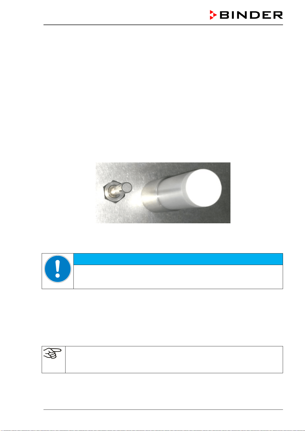
4.2.1 Connecting the CO
2
sensor
Turn off the chamber. Open the door of the inner chamber and plug the CO
2
sensor (4) into the perma-
nently installed holding tube located in the upper part of the rear of the inner chamber.
Figure 10: Plugged-in CO
2
sensor (right) and gas mixing head for CO
2
The sensor must click in correctly and sit tightly in the connection socket.
NOTICE
Danger of damage to the CO
2
sensor by connecting or removing it during operation.
Damage to the CO
2
sensor.
Connect or remove the CO
2
sensor only with the chamber turned off.
4.2.2 General notes
Connect or remove the CO
2
sensor without rotating and only when the incubator is turned off. Remove
the CO
2
sensor before removing or replacing its filter cap. The PTFE filter of the CO
2
sensor prevents dirt
and humidity from intruding into the measuring cell. It is available as a spare part. Replace it whenever it
is damaged or soiled.
The accuracy of the indicated values of CO
2
depends on the ambient air pressure (approx.
0.08 vol.-% per 10 mbar / 0.15 psi). In order to compensate this effect when measuring the
CO
2
concentration, the altitude of the installation site above sea level can be entered into the
controller (chap. 6.4).
CB-S / CB-S-UL (E7) 06/2020 page 29/119
The CO
2
sensor is temperature resistant up to a maximum temperature of 60 °C / 140 °F.
NOTICE
Danger of damage to the CO
2
sensor by excess temperature.
Damage to the CO
2
sensor.
∅ Do NOT autoclave the CO
2
Sensor.
∅ Do NOT expose the CO
2
sensor to hot-air sterilization..
The CO
2
sensor head was especially adjusted for the specific chamber. To avoid confusion, an adhesive
label with a serial number is adhered to the sensor head. When exchanging the sensor, you must repeat
the CO
2
adjustment.
NOTICE
Danger of confusing CO
2
sensors.
Invalid calibration.
Do NOT change the CO
2
sensor head.
Note down the serial number of the CO
2
sensor.
Avoid strong shocks when handling the CO
2
sensor.
NOTICE
Danger of damage to the CO
2
sensor by shocks.
Damage to the CO
2
sensor.
Avoid strong shocks of the CO
2
sensor (by putting it down hard, or dropping).
4.3 Water pan
The water pan permits high humidity without condensation on the inner walls of the CO
2
incubator.
Place the water pan in central position on the bottom of the inner chamber. Place the water pan with its
narrow side centrally between the front cams on the bottom of the inner chamber.
Figure 11: Position of the water pan centrally between the front cams (arrows)
CB-S / CB-S-UL (E7) 06/2020 page 30/119
Make sure that the water pan has firm contact with the inner chamber bottom and rests tightly on it.
Fill the water pan with 1 liter of distilled, sterilized water.
We recommend cleaning (chap. 22.1) and refilling the pans 2 to 3 times a week. For evacuation, remove
the water pan.
We recommend using distilled, sterile water to achieve optimum growth results. Any corrosive damage
that may arise following use of water of different quality or by additives is excluded from the liability
agreement.
If required, you can add microbiologically inhibiting substances such as copper chips, copper sulphate or
ethylene diamine tetra-vinegar acid (EDTA) in a concentration of
1 to 5 mmol/l.
Empty the water pan before moving the incubator. In case of the contents spilling, immediately shut down
the incubator and dry it carefully and completely.
4.4 Gas connection
General information for safe handling of gas cylinders:
• Store and use gas cylinders only in well ventilated areas.
• Open the gas cylinder valve slowly to avoid pressure surges
• Secure gas cylinders during storage and use against falling (chaining).
• Transport gas cylinders with a cylinder cart, do not carry, roll, or throw them
•
Always close the valve even with apparently empty cylinders; screw on the cap when not in
use. Return gas cylinders with the valve closed
• Do not open gas cylinders by force. Mark them when damaged
• Protect gas cylinders against fire, e.g. do not store together with flammable liquids
• Observe relevant regulations for dealing with gas cylinders.
Secure the gas cylinders against falling and other mechanical damage.
WARNING
Risk of injury through sudden release of the stored pressure energy when the valve
safety is torn off.
Injuries.
Secure gas cylinders against falling (chaining).
Transport gas cylinders with a cylinder cart.
The valve of the gas cylinder always must be closed before screwing on or unscrewing the gas hose.
WARNING
Risk of injury through sudden release of the stored pressure energy when opening
the cylinder valve of a not connected cylinder.
Injuries.
Close the gas cylinder valve before connecting or removing the gas hose.
After connecting the gas cylinder, check all gas connections for leaks (e.g. with leak spray or
diluted soap solution).
CB-S / CB-S-UL (E7) 06/2020 page 31/119
4.4.1 Connecting the CO
2
gas cylinder
Carbon dioxide (CO
2
) in high concentrations is hazardous to health. It is colorless and almost odorless
and therefore practically imperceptible. Vent out any CO
2
gas that may escape via good room ventilation
or a suitable connection to an exhaust system. We recommend installing a CO
2
warning system.
DANGER
Danger of suffocation and poisoning by high concentration of CO
2
(> 4 Vol.-%).
Death by suffocation.
∅ Do NOT set up chambers in non-ventilated recesses.
Ensure technical ventilation measures.
Observe the relevant regulations for handling CO
2
.
Close the CO
2
supply when decommissioning the chamber.
The CO
2
gas necessary for operation must have a technical grade of 99.5 %.
The gas connections must be established by qualified personnel who are trained in handling
the respective gases and familiar with the required safety measures.
The following steps are required:
Ensuring the correct CO
2
output pressure
A gas supply pressure above 2.5 bar / 36 psi will result in chamber damage.
Use a pressure reducer and make sure to avoid any excessive outlet pressure when connecting the
gas hose to the incubator.
The real outlet pressure of gas cylinders, sets of gas cylinders or central gas supplies am on the sec-
ond manometer must not exceed 2.5 bar / 36 psi.
NOTICE
Danger of damage by excessive outlet pressure > 2.5 bar / 36 psi.
Damage to the chamber.
∅ The outlet pressure must NOT exceed the indicated value of 2.5 bar / 36 psi.
Before connecting, check the outlet pressure on the pressure reducer of the cylin-
der.
Adjust the outlet pressure to 2.0 bar / 29 psi above the ambient pressure.
Observe the correct outlet pressure also when replacing the gas cylinders.
Establishing the connection to the incubator
Connect the supplied gas hose (internal diameter 6 mm / 0.24 inches) to the pressure reducer of the
gas cylinders or central gas supply and secure the connection with the supplied hose clamp.
Connect the pre-assembled hose nozzle of the gas hose to the quick acting closure socket (14) DN 6
on the chamber rear, as described in chap. 4.4.2.
Leak test
After connecting the gas cylinder, check all gas connections for leaks (e.g. with leak spray or diluted soap
solution).
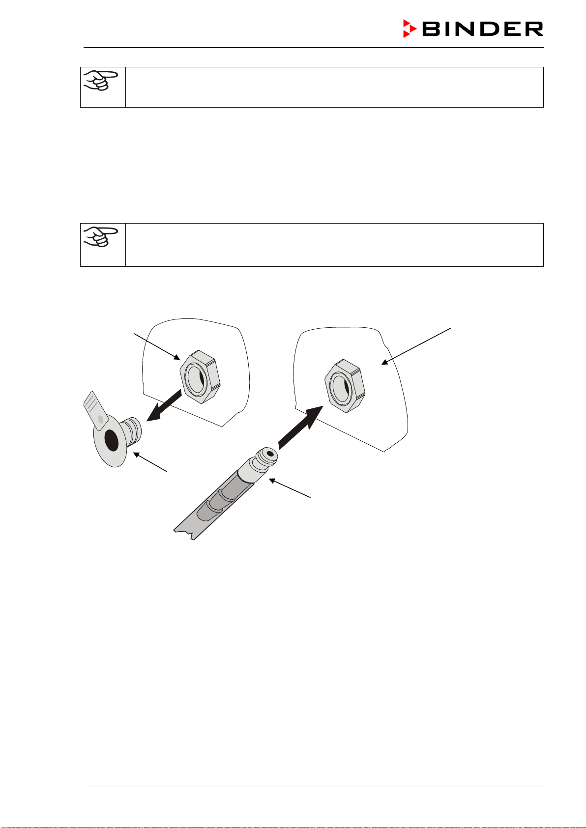
CB-S / CB-S-UL (E7) 06/2020 page 32/119
The recovery times of the gas concentrations inside the chamber after opening the door are
indicated in the technical data (chap. 26.4) and refer to a connection pressure of 2.0 bar / 29
psi. Decreasing supply pressure will result in longer recovery times.
Conversion table for gas inlet pressures, bar – psi, see chap. 26.6.
4.4.2 Connecting the gas hose to the chamber rear
The gas hose, which will be used to establish the connection to a gas cylinder, is already attached to the
hose nozzle and secured by a hose clamp. Plug the hose nozzle into the corresponding quick acting clo-
sure socket (a) located at the rear of the chamber. This quick acting closure socket is closed by a rubber
cover (b).
Only use the supplied hose nozzle to connect to the quick acting closure socket.
Otherwise, the quick acting closure socket may leak, and/or it may become impossible to con-
nect the original hose nozzle. In this case, please contact BINDER Service.
Remove the rubber cover (b) by pulling it off.
Chamber rear
Figure 12: Connection of the hose lead to the gas cylinder
Now fit the hose nozzle (c) in the quick acting closure socket. To remove the connection, pull the hose
nozzle off the quick acting closure socket.
(a)
(c)
(b)
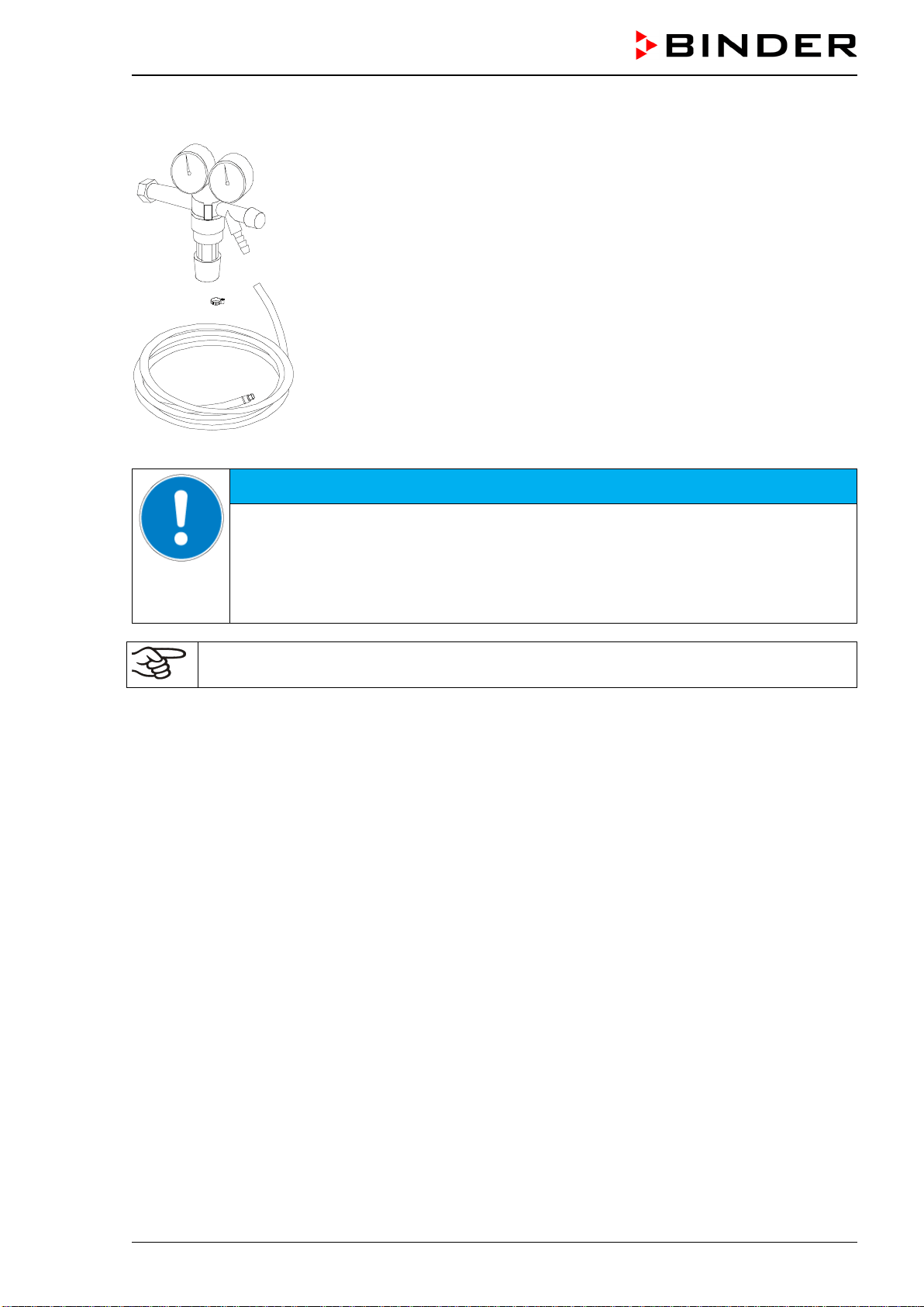
CB-S / CB-S-UL (E7) 06/2020 page 33/119
4.4.3 Gas cylinder connection kit (option)
The gas cylinder connection kit for CO
2
(Art. no. 8012-0014) includes the
following parts for connecting a gas cylinder to the CO
2
incubator:
• Pressure reducer with manometers for cylinder pressure (high pressure
gauge) and outlet pressure (low pressure gauge)
• 5 m pressure hose with pre-assembled hose nozzle for quick acting clo-
sure socket
• 1 hose clamp to connect the gas hose to the pressure reducer
The pressure reducer is also available as an individual accessory.
Figure 13: Gas cylinder connection kit
NOTICE
Danger of damage by excessive outlet pressure > 2.5 bar / 36 psi.
Damage to the chamber.
∅ The outlet pressure must NOT exceed the indicated value of 2.5 bar / 36 psi.
Before connecting, check the outlet pressure on the pressure reducer of the cylinder.
Adjust the outlet pressure to 2.0 bar / 29 psi above the ambient pressure.
The gas connections must be established by qualified personnel who are trained in handling
the respective gases and familiar with the required safety measures.
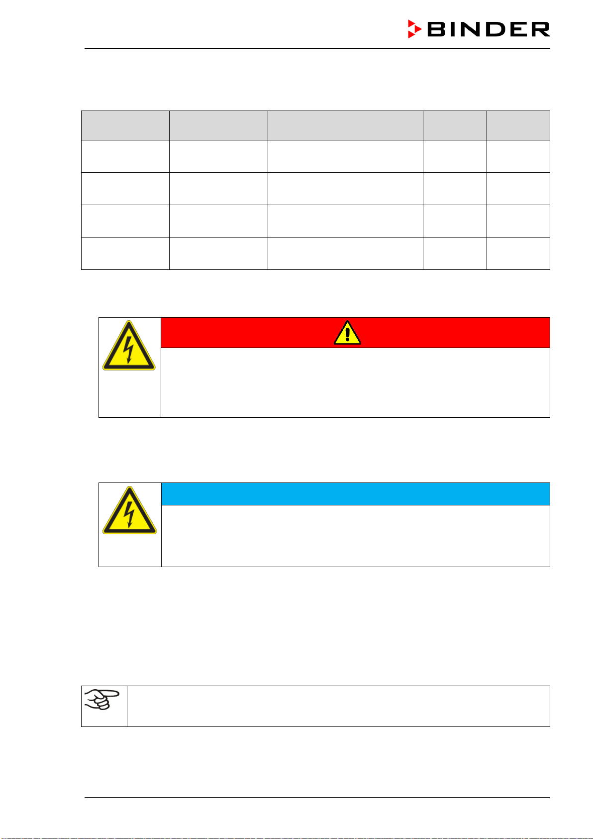
CB-S / CB-S-UL (E7) 06/2020 page 34/119
4.5 Electrical connection
The chambers are supplied ready for connection. They come with an IEC connector plug.
Model Power plug
Nominal voltage +/- 10% at the
indicated power frequency
Current
type
Chamber
fuse
CB-S 170
Grounded plug
IEC 7/7
200-230 V at 50 Hz
200-230 V at 60 Hz
1N~ 10 A
CB-S 170-UL
NEMA 5-20P
100-120 V at 50 Hz
100-120 V at 60 Hz
1N~ 16 A
CB-S 260
Grounded plug
IEC 7/7
200-230 V at 50 Hz
200-230 V at 60 Hz
1N~ 10 A
CB-S 260-UL NEMA 5-20P
100-120 V at 50 Hz
100-120 V at 60 Hz
1N~ 16 A
• The domestic socket must also provide a protective conductor. Make sure that the connection of the
protective conductor of the domestic installations to the chamber’s protective conductor meets the lat-
est technology. The protective conductors of the socket and plug must be compatible!
DANGER
Electrical hazard due to missing protective conductor connection.
Deadly electric shock.
Make sure that the chamber’s power plug and the power socket match and secure-
ly connect the electrical protective conductors of the chamber and the house instal-
lation.
• Only use original connection cables from BINDER according to the above specification.
• Prior to connection and start-up, check the power supply voltage. Compare the values to the specified
data located on the chamber’s type plate (centrally located at the bottom of the left-hand side of the
chamber, see chap. 1.6).
NOTICE
Danger of incorrect power supply voltage due to improper connection.
Damage to the chamber.
Check the power supply voltage before connection and start-up.
Compare the power supply voltage with the data indicated on the type plate.
• When connecting the chamber, please observe the regulations specified by the local electricity supply
company as well as the local and national regulations (VDE directives for Germany).
• Make sure that there is sufficient current protection in accordance with the number of devices that are
to be operated. We recommend the use of a residual current circuit breaker.
• Pollution degree (acc. to IEC 61010-1): 2
• Over-voltage category (acc. to IEC 61010-1): II
See also electrical data (chap. 26.4).
To completely separate the chamber from the power supply, you must disconnect the power
plug. Install the chamber in a way that the power plug is easily accessible and can be easily
pulled in case of danger.
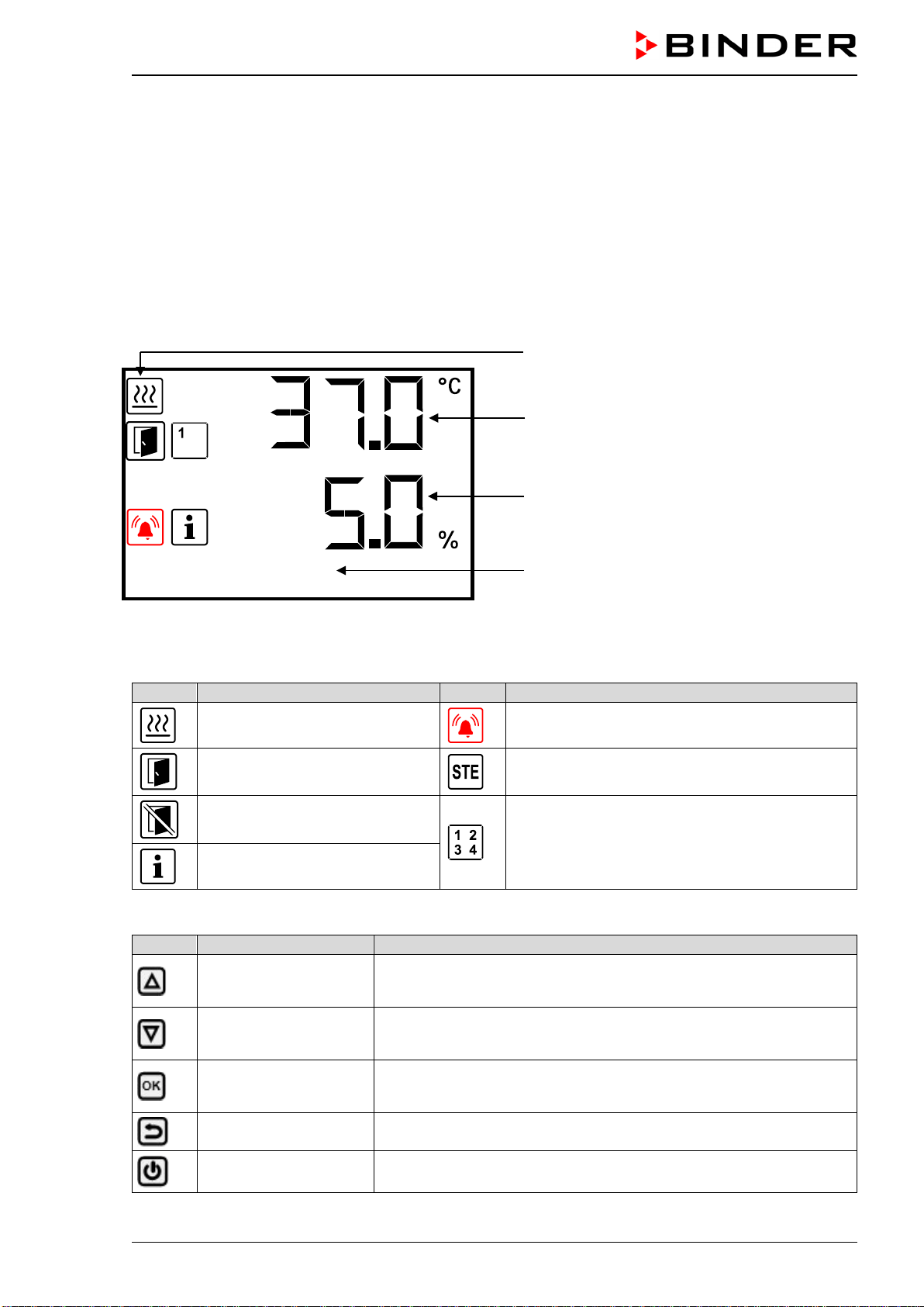
CB-S / CB-S-UL (E7) 06/2020 page 35/119
5. Functional overview of the RD4 chamber controller
The RD4 chamber controller controls following parameters inside the chamber:
• Temperature in °C or °F (range 6 °C / 10.8 °F above ambient temperature up to 50 °C / 122 °F)
• Carbon dioxide concentration in vol.-% (range 0 vol.-% up to 20 vol.-%)
You can enter the desired set point values in the “Set points” menu directly at the controller or use the
APT-COM™ 4 Multi Management Software (option) specially developed by BINDER.
The controller offers various notifications and alarm messages with visual and audible indication. All con-
troller setting remain valid until the next manual change. They are stored also after turning off the cham-
ber.
Status icons
Temperature value
CO
2
value
Text information
Temp. / CO2
Figure 14: Normal display of the RD4 controller (sample values)
Status icons in the controller display
Icon
Signification
Icon
Signification
Heating active
Collective alarm
Door open
Hot air sterilization running
Do not open the door!
Display of activated special controller functions:
1 = Idle mode
2 = CO
2
control deactivated
Information
Functional controller keys
Icon
Signification
Function
Arrow-up button
• Navigate between menus, submenus, other functions
• In the setting menu: change setting, increase value
Arrow-down button
• Navigate between menus, submenus, other functions
• In the setting menu: change setting, decrease value
OK button
• Select menu, submenu, function
• In the setting menu: Confirm entry
Back button Back to previous menu level
Standby button
No function
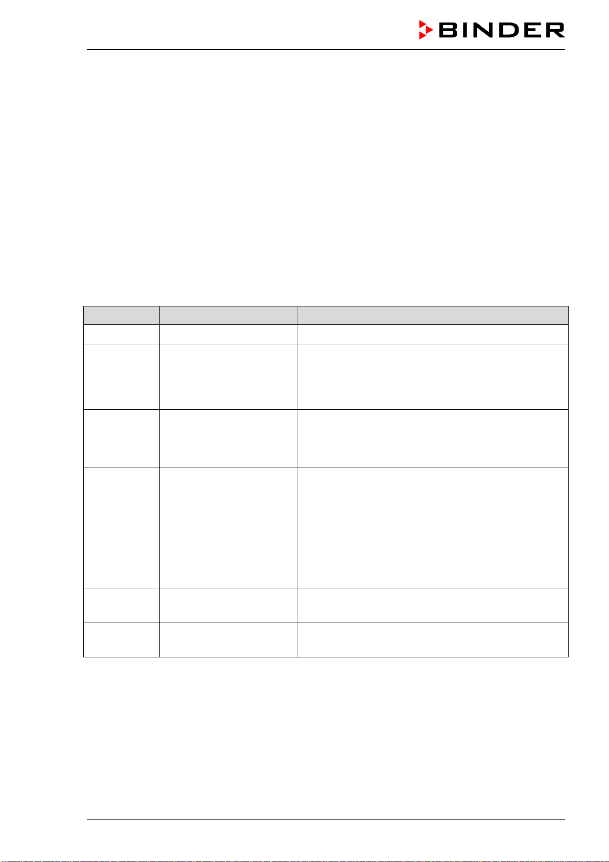
CB-S / CB-S-UL (E7) 06/2020 page 36/119
5.1 Menu structure of the controller and access levels
Starting from Normal display, navigate between the menus with the arrow buttons.
With the OK button you enter the setting of further subordinate menu functions.
With the Back button you go back to the previous function and finally back to Normal display.
The available functions depend on the current dependent on the current authorization “User”, “Admin” or
“Service”, for which the entry of a password may be required, depending on the setting.
You can set passwords for different access levels:
• User: The password enables access to the standard operating functions. Factory setting is 00 00 (no
password assigned).
• Admin: The password enables access to advanced controller functions and settings. Factory setting is
00 01.
• Service: The password enables access to all controller functions (for BINDER Service only).
As soon as a password has been assigned, access to the respective functions is blocked and only avail-
able after entering the correct password.
Menu Required access level Functions
Sterilization “User”
• Activating/deactivating the sterilization
Setpoints “User”
• Temperature and CO
2
set-point setting
• Change to Idle mode
• Turning on / off CO
2
control
• Setting the safety controller
Chamber info Any user
• Configuration display (setup information, controller
hardware and software, analog inputs)
•
Display of interface configuration (e.g. MAC address,
IP address)
Settings “Admin”
• General controller settings (date, time, menu language,
temperature unit, display brightness…)
• Network settings
• Setting the data logger storage interval
• Setting the altitude above sea level
•
Setting the tolerance range limits and delay time for
door and tolerance range alarm
• Password changing for User and Admin
Service “Service”
• Configuration settings (only for BINDER Service)
• Password changing for User and Admin
USB Export: Any user
Import: “Admin”
• Export of configuration, logger, and service data
• Import of configuration data
Unless noted otherwise, the figure in this manual show the functional range, which is available for the
user with “Admin” authorization level
Note: When specifying the path to the respective function, the possibly required entry of a password is not
listed
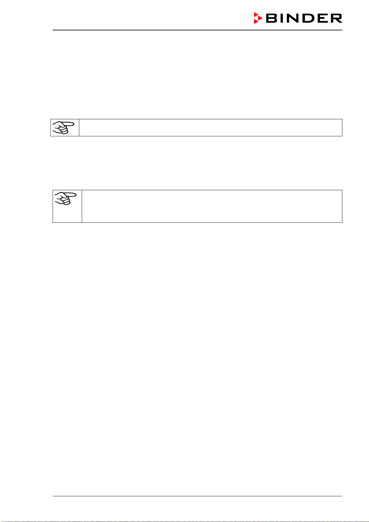
CB-S / CB-S-UL (E7) 06/2020 page 37/119
5.2 Performance during and after power failures and shut down
In the event of power failure, all controller functions are shut down. The gas inlet valves are closed so that
no gas can escape into the ambient air. The zero-voltage relay alarm output (13) (chap. 15.4.1) is
switched to alarm position indicating the alarm for the whole duration of the power failure.
After the power returns or after turning on the chamber, all functions return to the same status the cham-
ber had before power failure. The set-points are immediately resumed.
If the chamber was in sterilization mode, the process is cancelled and the chamber continues normal
operating mode with the original set points previously entered .
All settings and set point values remain in the memory during power failure after power off.
6. Start up
Check that the interior of the chamber is empty, including the trays and the water pan. If you do not know
what the chamber was last used for, for hygiene purposes you should clean and disinfect or sterilize the
interior (chap. 22).
WARNING: If customer should use a BINDER chamber running in non-supervised continu-
ous operation, we strongly recommend in case of inclusion of irrecoverable specimen or
samples to split such specimen or samples and store them in at least two chambers, if this is
feasible.
Warming chambers may release odors in the first few days after commissioning. This is not a quality de-
fect. To reduce odors quickly we recommend heating up the chamber to its nominal temperature for one
day and in a well-ventilated location.
6.1 Turning on the chamber
Open the CO
2
supply's pressure reducer valve and set a CO
2
primary pressure of 2.0 bar / 29 psi.
After connecting the supply lines, turn on the chamber by the main power switch (2). The lit pilot lamp
shows the chamber is ready for operation.
The controller shows normal display and controls the temperature and CO
2
to the last entered values.
After turning on the chamber for the first time, enter the altitude of the site above sea level into the con-
troller (chap. 6.4).
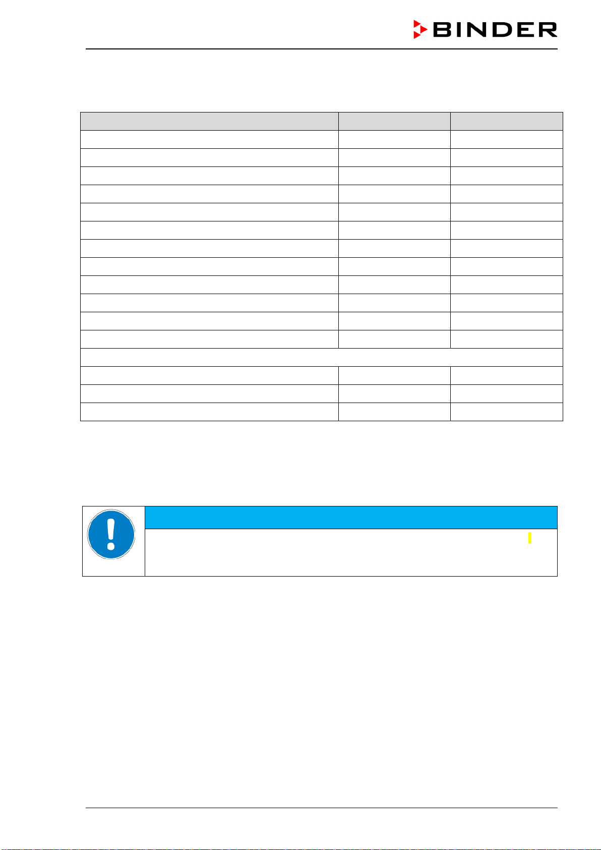
CB-S / CB-S-UL (E7) 06/2020 page 38/119
6.2 Preset factory parameters
The chamber is supplied with the following basic preset parameters:
Parameter Factory setting Setting / modification
Temperature set point
37.0 °C / 98.6°F chap. 7.1
CO
2
set point
5.0 vol.-% chap. 7.2
Safety controller mode “Offset” chap. 11.2.1
Safety controller value 2.0 °C chap. 11.2.2
Sterilization temperature set point 190 °C / 374 °F fix
Installation height above sea level 650 m / 2132.54 ft chap. 6.4
Temperature tolerance range +/- 1.0 K chap. 13.2
CO
2
tolerance range
+/- 1.0 vol.-%
chap. 13.3
Delay time for tolerance range alarms 10 min chap. 13.1
Delay time for door open alarms 1 min chap. 13.4
Password for “User” access level. 0 chap. 10.2.1
Password for “Admin” access level. 1 chap. 10.2.2
The following settings should only be modified by BINDER service:
Humidity control 0 % r.h. chap. 14.1
Door heating Offset value 3.0 °C chap. 14.2
Adjustment factor of the heating power 12.0 chap. 14.3
6.3 Performance after turning on the chamber
During the equilibration phase of 2 hours after turning on the chamber, undefined temperature and CO
2
conditions occur within the chamber. During this phase, do not place any sample materials in the cham-
ber.
HINWEIS
Danger of undefined temperature and CO
2
conditions in the equilibration phase.
Destruction of samples.
Load the chamber only after equilibration of temperature and CO
2
.
If the function “Language selection at restart” has been activated (chap. 12.5, factory setting ON), the
following settings are checked upon start up:
• Menu language (chap. 12.1):
Use the arrow buttons to select the desired language, confirm with the OK button
• Temperature unit (chap. 12.2):
Use the arrow buttons to select the desired temperature unit, confirm with the OK button.
• Current date (chap. 12.3), format DD MM YYYY:
Use the arrow buttons to set the day, continue with the OK button.
Use the arrow buttons to set the month, continue with the OK button.
Use the arrow buttons to set the year, confirm with the OK button
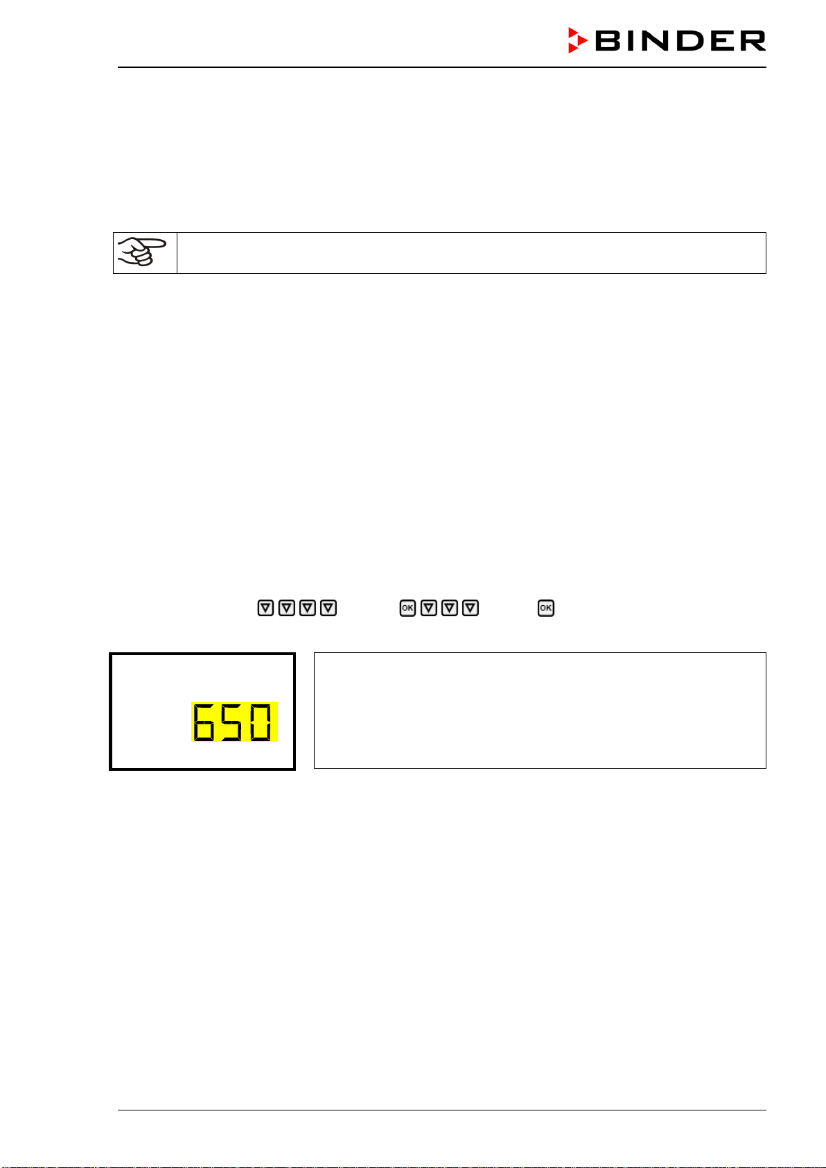
CB-S / CB-S-UL (E7) 06/2020 page 39/119
• Current time (chap. 12.4), format HH:MM:
Use the arrow buttons to set the hours, continue with the OK button.
Use the arrow buttons to set the minutes, confirm with the OK button
Set the controller to the desired temperature, and CO
2
set points that shall be used to operate the cham-
ber (chap. 7).
Only insert samples into the chamber when it has reached its stable operating state.
If there is no accordance between the actual and set value shown in the display, proper opera-
tion of the chamber is not guaranteed.
Temperature: Equilibration time is approx. 2 hours.
CO
2
: After approx. 5 minutes, the CO
2
concentration equilibrates automatically to the preset value.
Instructions when observing leakage of condensate from the CO
2
sensor system and CO
2
fluctua-
tion:
In the case of CO
2
fluctuations and concomitant condensate leakage from the injection and suction noz-
zle of the CO
2
sensor compartment after start-up or when taking the chamber back into service, the
chamber should be left to dry open for at least an hour running at 37 °C with the water pan empty. This
will result in flushing the sensor compartment and tubing from humid air. Removing the condensate from
the CO
2
sensor system will ensure a turbulence-free CO
2
measurement.
6.4 Altitude of the installation site above sea level
After first turning on the incubator, enter the altitude of the site above sea level into the RD4controller.
This entry serves to correct the calculation of CO
2
concentration in vol.-% from the measurement of par-
tial pressure. The setting will remain stored after shutting the power off.
Required access level: “Admin”.
Path: Normal display Settings Various Altitude
Press the OK button to enable the setting.
Setting the altitude.
The current setting flashes. Enter the desired altitude. Entry range: 0 m
/ 0 ft up to 2000 m / 6562 ft.
Confirm the entry with the OK button.
Altitude (m)
With the Back button you can go back to the “Various” submenu and, repeatedly pressing it, to Normal
display.
Unit of altitude
above sea level for entry and displayed value: kilometer [km]
Correlation feet [ft] to kilometer [km]: see chap. 26.5.
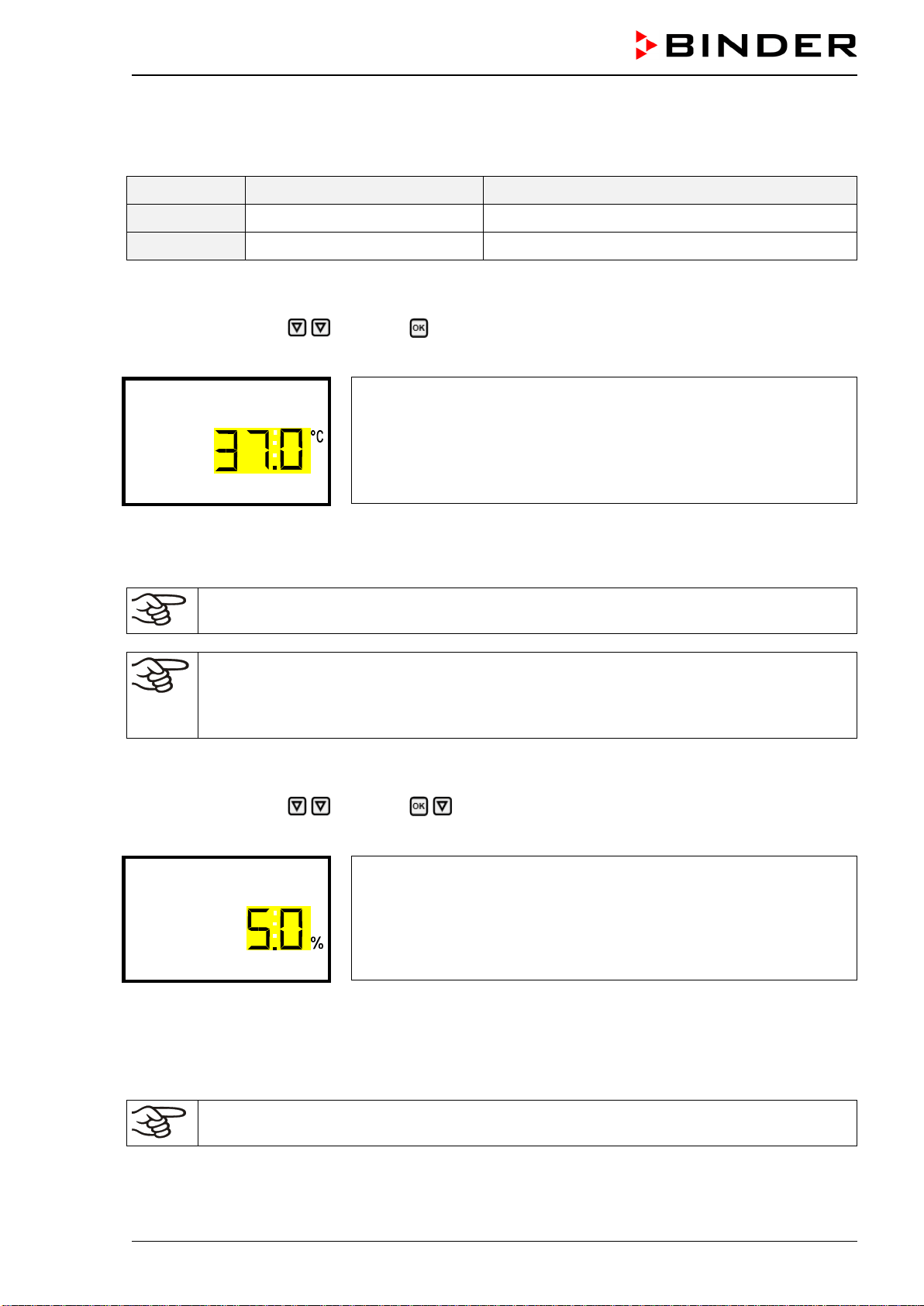
CB-S / CB-S-UL (E7) 06/2020 page 40/119
7. Temperature and CO
2
set-point entry
Required access level: “User”.
Setting ranges Control ranges
Temperature 0 °C / 32 °F up to 50 °C / 122 °F 6 °C / 10.8 °F above ambient up to 50 °C / 122 °F
Humidity 0 vol.-% up to 20 vol.-% 0 vol.-% up to 20 vol.-%
7.1 Temperature set-point entry
Path: Normal display Setpoints Temperature
Press the OK button to enable the setting.
Temperature setting.
The current setting flashes. Enter the desired set-point with the arrow
buttons.
Confirm the entry with the OK button.
Temperature
With the arrow-down button you can continue with the CO
2
set-point entry (chap. 7.2).
With the Back button you can go back to the “Setpoints” submenu and, repeatedly pressing it, to Nor-
mal display.
When setting a lower temperature set point, in order to save time, we recommend cooling
down the chamber by turning it off and opening the chamber doors.
With safety controller mode “Limit”, adapt the safety controller always when you changed the
temperature set-point. Set the safety controller value by approx. 2 °C above the temperature
set-point (chap. 11.2).
Recommended setting: safety controller mode “Offset” with safety controller value 2 °C.
7.2 CO
2
set-point entry
Path: Normal display Setpoints CO2
Press the OK button to enable the setting.
CO
2
set-point setting
The current setting flashes. Enter the desired set-point with the arrow
buttons.
Confirm the entry with the OK button.
CO2
With the arrow-up button you can go back to the temperature set-point entry (chap. 7.1)
With the arrow-down button you can now change to the special controller functions setting (chap. 9)
With the Back button you can go back to the “Setpoints” submenu and, repeatedly pressing it, to Nor-
mal display.
When setting a lower CO
2
set point, the CO
2
gas must be able to escape first. Open the
chamber doors for this purpose.
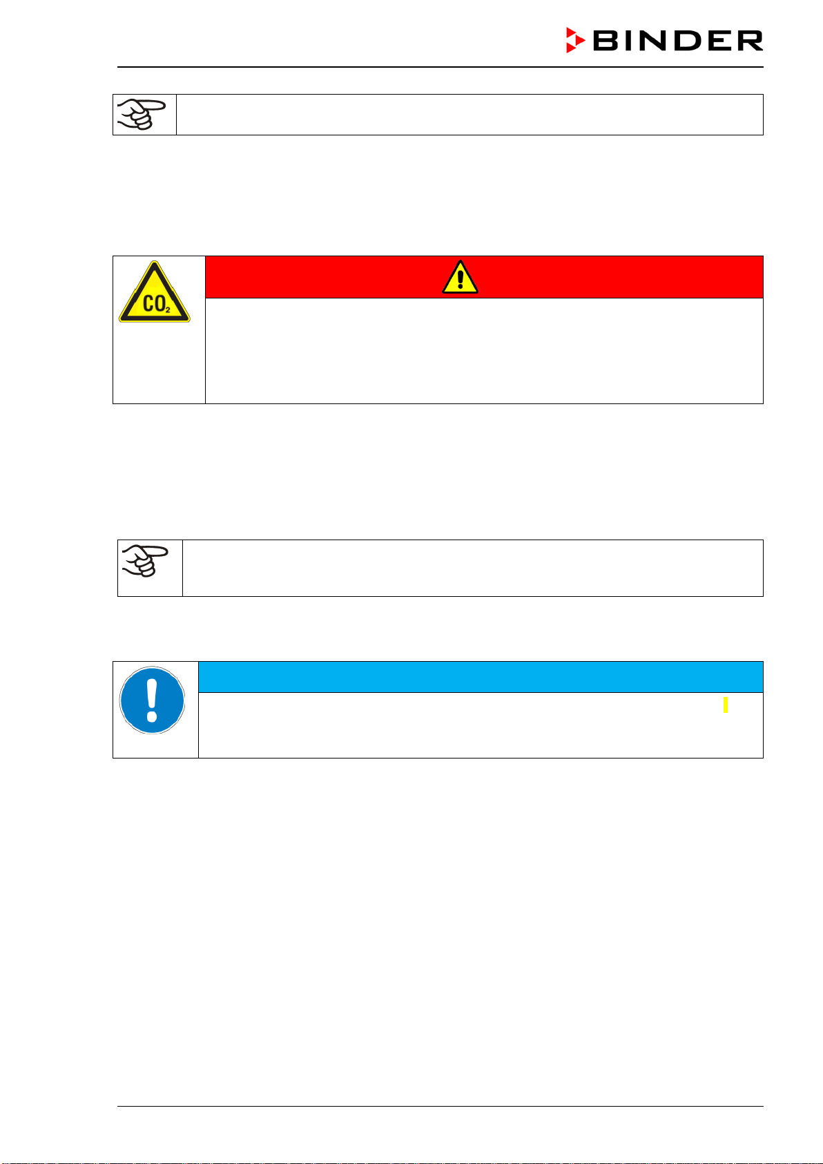
CB-S / CB-S-UL (E7) 06/2020 page 41/119
If no CO
2
concentration is indicated (display showing “ – – – – ”) the CO
2
sensor is not con-
nected.
Note when setting high gas concentrations
Carbon dioxide (CO
2
) in high concentrations is hazardous to health. It is colorless and almost odorless
and therefore practically imperceptible. Any CO
2
gas that may escape must be safely led out via good
room ventilation or a suitable connection to an exhaust system. We recommend installing a CO
2
warning
system.
DANGER
Danger of suffocation and poisoning by high concentration of CO
2
(> 4 Vol.-%).
Death by suffocation.
∅ Do NOT set up chambers in non-ventilated recesses.
Ensure technical ventilation measures.
Observe the relevant regulations for handling CO
2
.
If CO
2
is released, leave the area und inform the security service or fire department.
8. Placing samples in the incubator
In order to detect possible transport damages we recommend a 1 or 2 days test run at the desired set-
points before placing valuable samples. Then you can load the chamber with the samples.
WARNING: If customer should use a chamber running in non-supervised continuous opera-
tion, we strongly recommend in case of inclusion of irrecoverable specimen or samples to
split such specimen or samples and store them in at least two chambers, if this is feasible.
During the equilibration phase of approx. 2 hours after turning on the chamber, undefined temperature
and CO
2
conditions occur within the chamber. During this phase, do not place any sample materials in
the chamber.
HINWEIS
Danger of undefined temperature and CO
2
conditions in the equilibration phase.
Destruction of samples.
Load the chamber only after equilibration of temperature and CO
2
.
Do not exceed the maximum load of each shelf and the permitted total load (see chap.26.4).
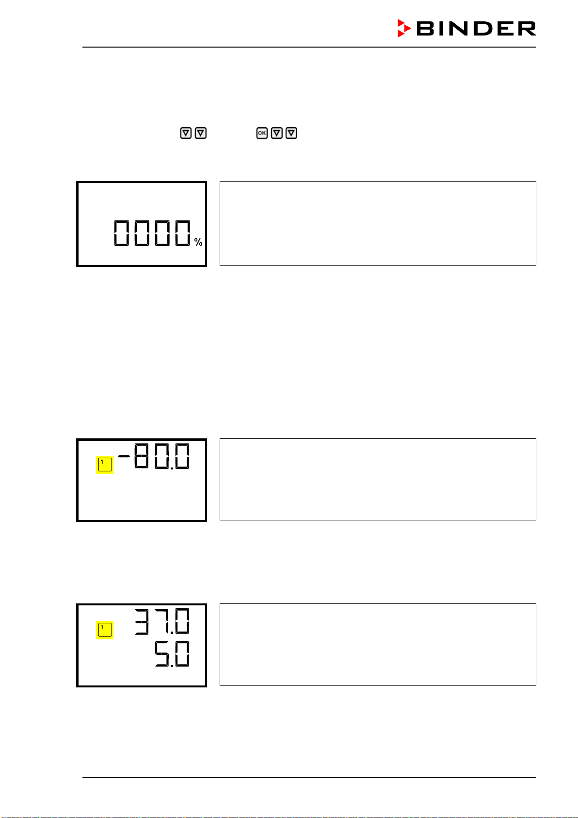
CB-S / CB-S-UL (E7) 06/2020 page 42/119
9. Setting special controller functions
In the “Functions on/off” menu you can define the switching state of the special controller functions.
Required access level: “User”.
Path: Normal display Setpoints Functions on/off
The functions are displayed from left to right.
Example: Function 1 “Humidity off” activated = 1000. Function 1 “Humidity off” deactivated = 0000.
Submenu “Functions on/off”.
This view shows the switching states four functions.
“1” = Function activated
“0” = Function deactivated
Functions on/off
Press the OK button to access the first individual function. With the arrow-down button you can pro-
ceed to the subsequent functions.
• Function 1 “Idle mode”: Change to “Idle mode”, chap. 9.1
• Function 2 “CO2 off”: Deactivating CO
2
control, chap. 9.2
• Functions 3 and 4 have no function with this chamber type.
Press the OK button to enable the setting of the desired function and select the function’s switching state
“1” (function activated) or “0” (function deactivated).
With the Back button you can go back to the “Setpoints” submenu and, repeatedly pressing it, to Nor-
mal display.
In Normal display the activated functions are indicated by an icon showing the number of the respective
function.
Example:
Normal display with activated function 1 “Idle mode”.
Temp. / CO2
9.1 Idle mode
In this operating mode, temperature and CO
2
control are deactivated. The actual values continue to be
displayed in Normal Display. This operating mode is switched on or off via the controller function 1 “Idle
mode” (chap. 9). In Normal Display the activated function 1 is indicated by an icon showing the number 1.
Normal display in “Idle mode” (sample values)
Temp. / CO2
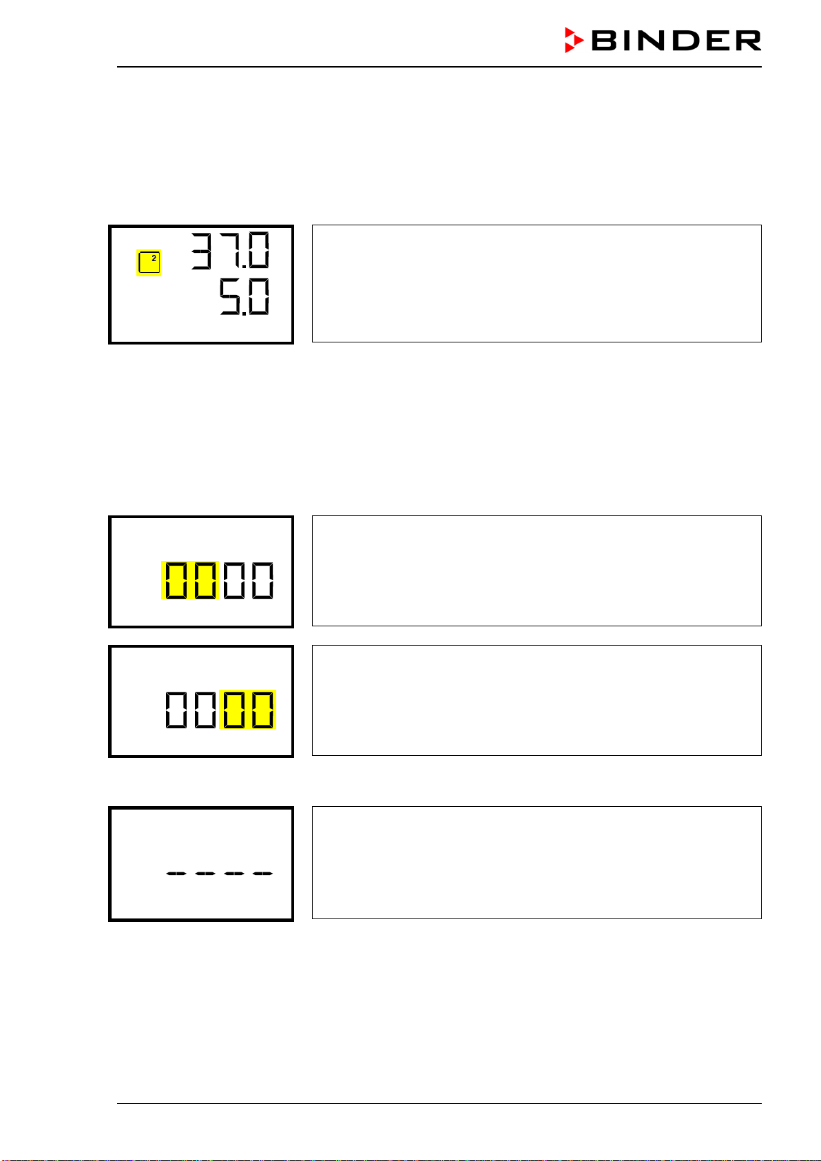
CB-S / CB-S-UL (E7) 06/2020 page 43/119
9.2 Deactivated CO
2
control
When operating the chamber without a CO2 gas connection, you can deactivate CO2 control with the
function “CO2 off” (chap. 9) to avoid alarms of the CO
2
gas system. No CO
2
tolerance range alarms and
no pressure alarm will be emitted.
The actual CO
2
value continues to be displayed in Normal Display. The activated function 2 is indicated
by an icon showing the number 2.
Normal display with deactivated CO
2
control (sample values)
Temp. / CO2
10. Password
10.1 Password request
To access menus for which access is restricted, you must enter the corresponding password.
After calling the appropriate menu function with the OK button the password request appears.
Password request.
The left two digits are flashing. Enter the desired numbers with the
arrow buttons.
Confirm the setting with the OK button.
Password
Password request.
The right two digits are flashing. Enter the desired numbers with the
arrow buttons.
Confirm the setting with the OK button.
Password
Upon entering an incorrect password, the information message “Wrong password” is displayed.
Display “Wrong password”.
After 3 seconds the controller changes again to the password entry.
Enter the correct password.
Wrong password
Following correct password entry you can access the desired menu function.
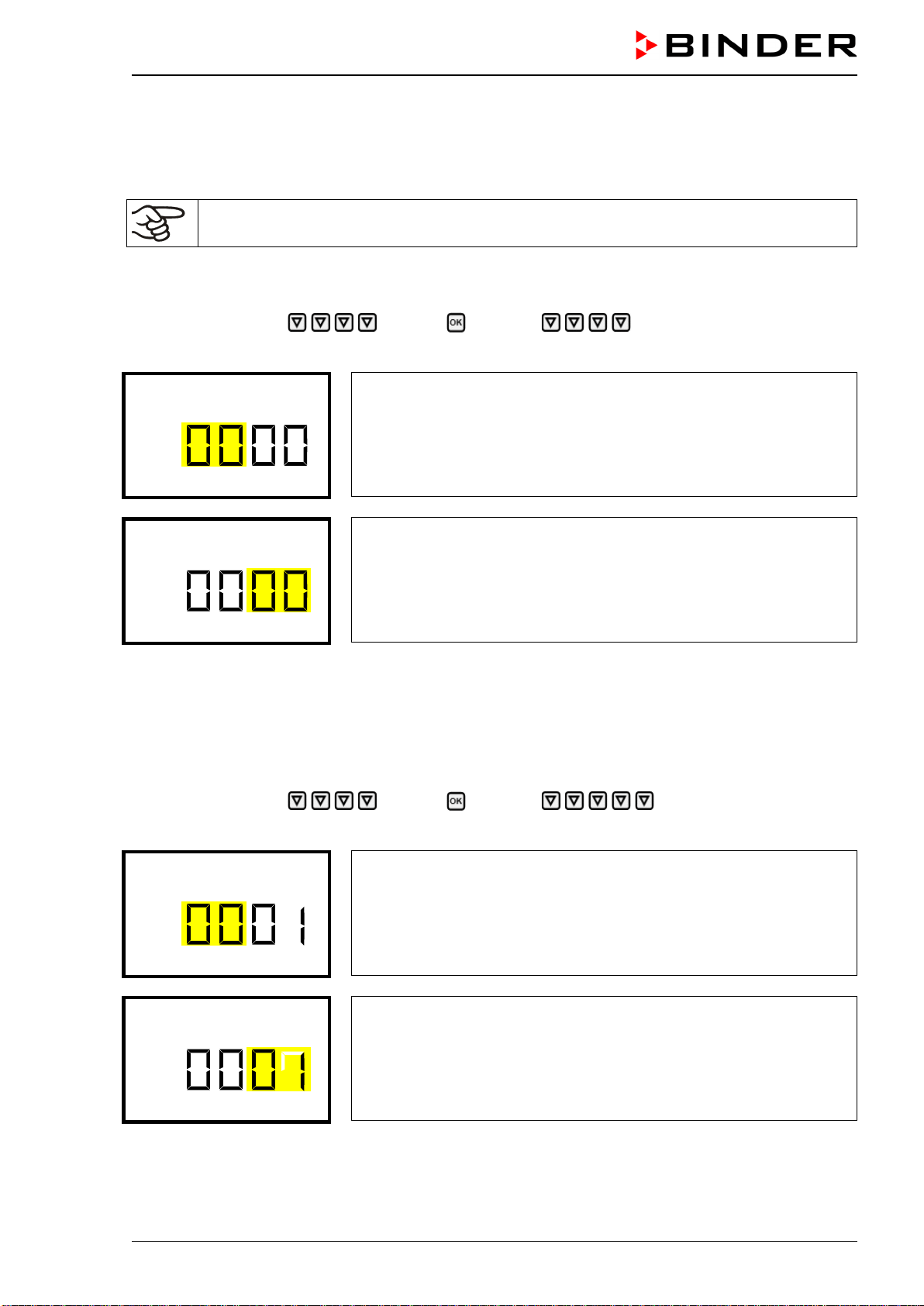
CB-S / CB-S-UL (E7) 06/2020 page 44/119
10.2 Assign and modify a password
In this menu you can assign and modify the passwords of the “User” and “Admin” access levels.
Required access level: “Admin”.
Keep the password well in mind. There is no access to the corresponding menu functions
without the correct password.
10.2.1 Assign and modify the User password
Path: Normal display Settings Chamber Password User
Press the OK button to enable the setting.
Setting the User password.
The left two digits are flashing. Enter the desired numbers with the
arrow buttons.
Confirm the setting with the OK button.
Password User
Setting the User password.
The right two digits are flashing. Enter the desired numbers with the
arrow buttons.
Confirm the setting with the OK button.
Password User
With the arrow-down button you can now proceed to enter the Admin password.
With the Back button you can go back to the “Chamber” submenu and, repeatedly pressing it, to Nor-
mal display.
10.2.2 Assign and modify the Admin password
Path: Normal display Settings Chamber Password Admin
Press the OK button to enable the setting.
Setting the Admin password.
The left two digits are flashing. Enter the desired numbers with the
arrow buttons.
Confirm the setting with the OK button.
Password Admin
Setting the Admin password.
The right two digits are flashing. Enter the desired numbers with the
arrow buttons.
Confirm the setting with the OK button.
Password Admin
With the Back button you can go back to the “Chamber” submenu and, repeatedly pressing it, to Nor-
mal display.
CB-S / CB-S-UL (E7) 06/2020 page 45/119
11. Temperature safety devices
11.1 Over temperature protective device (class 1)
The CO
2
incubator is equipped with one (CB-S-UL) or two (CB-S) internal temperature safety devices
class 1 acc. to DIN 12880:2007. They serve to protect the chamber and prevent dangerous conditions
caused by major defects.
If one of the over temperature protective devices permanently turns off the chamber, the user cannot
restart the device again. The protective cut-off devices are located internally. Only a service specialist can
replace them. Therefore, please contact an authorized service provider or BINDER Service.
11.2 Overtemperature safety controller class 3.1
The chambers are regularly equipped with an electronic overtemperature safety controller (temperature
safety device class 3.1 according to DIN 12880:2007). If an error occurs, the safety controller performs a
regulatory function.
Please observe the DGUV guidelines 213-850 on safe working in laboratories, issued by the employers’
liability insurance association (for Germany).
The overtemperature safety controller serves to protect the chamber, its environment and the contents
from exceeding the maximum permissible temperature. In the case of an error, it limits the temperature
inside the chamber to the entered safety controller value. This condition (state of alarm) is indicated visu-
ally and additionally with an audible alert if the buzzer is enabled (chap. 15.3). The alarm persists until the
chamber cools down below the configured safety controller value and the alarm is reset on the controller.
Check the setting regularly and adjust it following changes of the temperature set-point or
charge.
The safety controller only activates after the set-point has been reached once.
You can set the safety controller mode to “Limit” or “Offset”.
• Limit: Limit value, absolute maximum permitted temperature value
This setting offers high safety as a defined temperature limit will not be exceeded. It is important to
adapt the safety controller value after each modification of the temperature set-point. Otherwise, the
limit could be too high to ensure efficient protection, or, in the opposite case, it could prevent the con-
troller from reaching an entered set-point outside the limit range.
• Offset: Offset value, maximum overtemperature above any active temperature set point. The resulting
maximum temperature changes internally and automatically with every temperature set-point change.
Example:
Desired temperature value: 37 °C, desired safety controller value: 39 °C.
Possible settings for this example:
Temperature set point Safety controller mode Safety controller value
37 °C
Limit Limit value 39 °C
Offset Offset value 2 °C
Factory setting: Safety controller mode “Offset” with safety controller value 2 °C.
The settings of the safety controller are inactive during sterilization (chap. 23). They become
functional again following abortion of the sterilization and/or the restart of the chamber at the
main power switch.
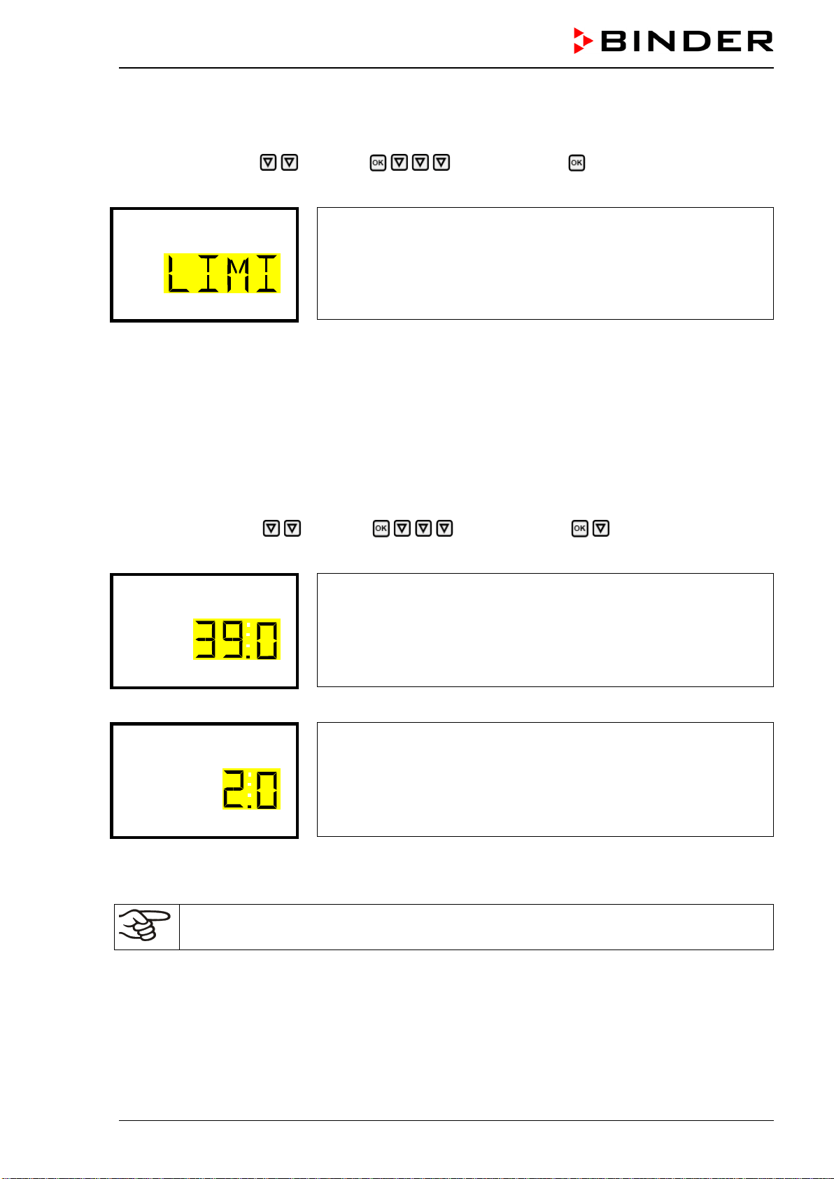
CB-S / CB-S-UL (E7) 06/2020 page 46/119
11.2.1 Setting the safety controller mode
Required access level: “User”.
Path: Normal display Setpoints Safety controller Mode
Press the OK button to enable the setting.
Setting the safety controller mode
The current setting flashes. Use the arrow buttons to select between
LIMI (Limit) and OFFS (Offset).
Confirm the setting with the OK button.
Mode
With the arrow-down button you proceed to setting the safety controller value (chap. 11.2.2)
With the Back button you can go back to the “Safety controller” submenu and, repeatedly pressing it, to
Normal display.
11.2.2 Setting the safety controller value
Required access level: “User”.
The desired safety controller mode must be selected first (chap. 11.2.1). Depending on the mode setting,
one of the following setting menus will appear.
Path: Normal display Setpoints Safety controller Limit or Offset
Press the OK button to enable the setting.
Setting the safety controller value with “Limit” safety controller mode.
The current value flashes. Enter the desired limit value with the arrow
buttons.
Confirm the entry with the OK button.
Limit
or
Setting the safety controller value with “Offset” safety controller mode
The current value flashes. Enter the desired offset value with the arrow
buttons.
Confirm the entry with the OK button.
Offset
With the Back button you can go back to the “Safety controller” submenu and, repeatedly pressing it, to
Normal display.
Regularly check the settings of the safety controller mode and value.
Set the safety controller value by approx. 2 °C above the desired temperature set-point.
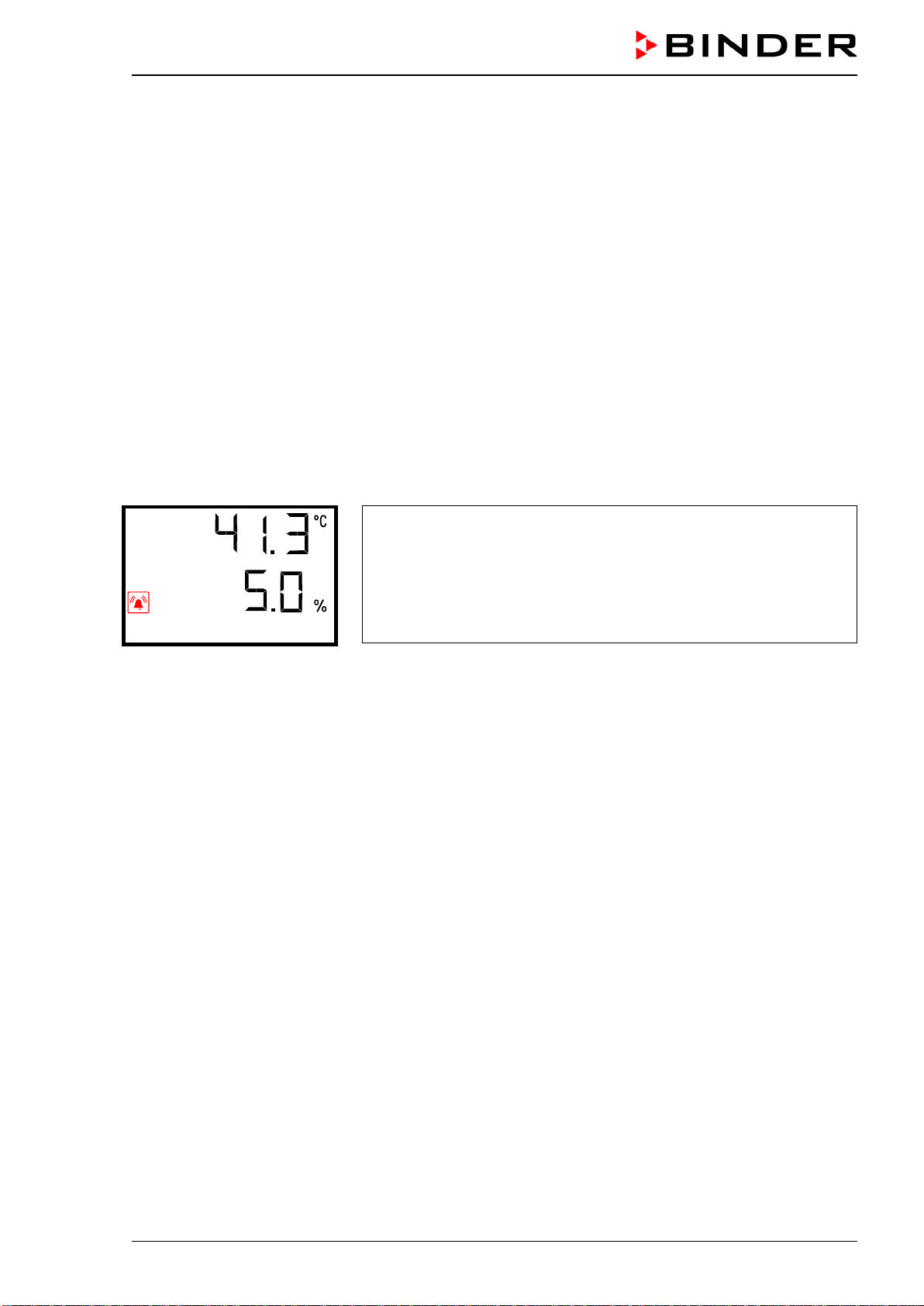
CB-S / CB-S-UL (E7) 06/2020 page 47/119
11.2.3 Message and measures in the state of alarm
The state of alarm is indicated visually in Normal display. If the buzzer is enabled (chap. 15.3) there is an
additional audible alert. The heating turns off. As soon as the inner chamber temperature has cooled
down below the safety controller value, the heating is released and temperature control continues.
In Normal display a text message indicates the alarm cause. The “collective alarm” icon flashes. If the
audible arm is activated, the buzzer sounds. Press the OK button to mute the buzzer.
The alarm message “Safety controller” and the “Collective alarm” icon are displayed on the controller until
you press the OK button on the controller and the inner chamber temperature has cooled down below
the safety controller value.
• If the inner chamber temperature has already cooled down below the safety controller value when
pressing the OK button, the alarm message “Safety controller” and the “Collective alarm” icon are re-
set together with the buzzer.
• If the state of alarm is still active when pressing the OK button, i.e. the inner chamber temperature is
still above the safety controller value, first only the buzzer is reset. The alarm message “Safety control-
ler” and the “Collective alarm” icon will disappear as soon as the inner chamber temperature falls be-
low the safety controller value.
• The alarm remains active until it is acknowledged on the controller and the inner temperature falls
below the entered safety controller setpoint. Then the heating is released again.
Normal display showing safety controller alarm (sample values)
Safety controller
Note:
When the safety controller class 3.1 had been activated you should disconnect the chamber from the
power supply and have an expert examine and rectify the cause of the fault.
11.2.4 Function check
Check the safety controller at appropriate intervals for its functionality. It is recommended that the author-
ized operating personnel should perform such a check, e.g., before starting a longer work procedure.
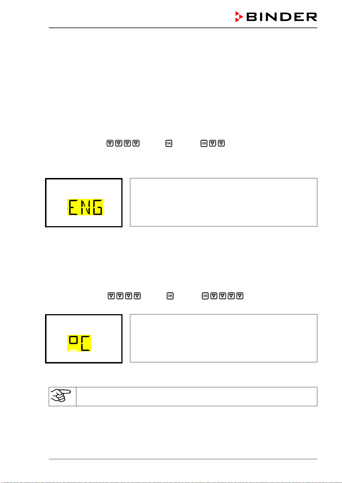
CB-S / CB-S-UL (E7) 06/2020 page 48/119
12. General controller settings
The general settings can be accessed in the “Settings” submenu, which is available for users with “Ser-
vice” or “Admin” authorization level. It serves to enter date and time, select the language for the controller
menus and the desired temperature unit and to configure the controller’s communication functions.
The display of some network settings is available for all users in the “Chamber info” menu.
12.1 Selecting the controller’s menu language
The RD4 controller communicates by a menu guide using real words in German, English, French, Span-
ish, and Italian languages.
Required access level: “Admin”. Following start-up of the chamber (chap. 6.3), it is “User”.
Path: Normal display Settings Chamber Language*
* Following start-up of the chamber: Sprache / Language / Langue / Idioma / Lingua, depending on the
language selected before turning off the chamber
Press the OK button to enable the setting.
Setting the menu language (example: English).
The current setting flashes. Use the arrow buttons to select the desired
language.
Confirm the entry with the OK button.
Language
With the arrow-down button (twice) you can now change to the temperature unit setting.
With the Back button you can go back to the “Chamber” submenu and, repeatedly pressing it, to Nor-
mal display.
12.2 Selecting the temperature unit
Required access level: “Admin”. Following start-up of the chamber (chap. 6.3), it is “User”.
Path: Normal display Settings Chamber Temperature unit
Press the OK button to enable the setting.
Setting the temperature unit
The current setting flashes. Use the arrow buttons to select between
°C (degrees Celsius) and °F (degrees Fahrenheit).
Confirm the entry with the OK button.
Temperature unit
You can change the temperature unit between °C and °F.
If the unit is changed, all values are converted accordingly
C = degree Celsius
F= degree Fahrenheit
0 °C = 31°F
100 °C = 212°F
Conversion:
[value in °F] = [value in °C] ∗ 1,8 + 32
With the Back button you can go back to the “Chamber” submenu and, repeatedly pressing it, to Nor-
mal display.
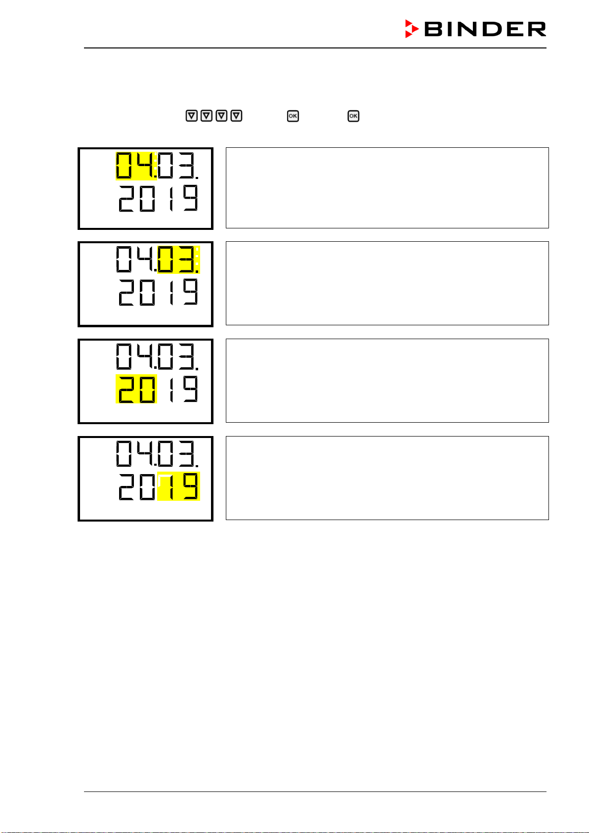
CB-S / CB-S-UL (E7) 06/2020 page 49/119
12.3 Setting the current date
Required access level: “Admin”. Following start-up of the chamber (chap. 6.3), it is “User”.
Path: Normal display Settings Chamber Date
Press the OK button to enable the setting.
Setting the date: day
The current setting flashes. Enter the current day with the arrow but-
tons.
Confirm the entry with the OK button.
Date
Setting the date: month
The current setting flashes. Enter the current month with the arrow
buttons.
Confirm the entry with the OK button.
Date
Setting the date: year
The left two digits are flashing. Enter the first two digits of the current
year with the arrow buttons.
Confirm the entry with the OK button.
Date
Setting the date: year
The right two digits are flashing. Enter the last two digits of the current
year with the arrow buttons.
Confirm the entry with the OK button.
Date
With the arrow-down button you can now change to setting the current time.
With the Back button you can go back to the “Chamber” submenu and, repeatedly pressing it, to Nor-
mal display.
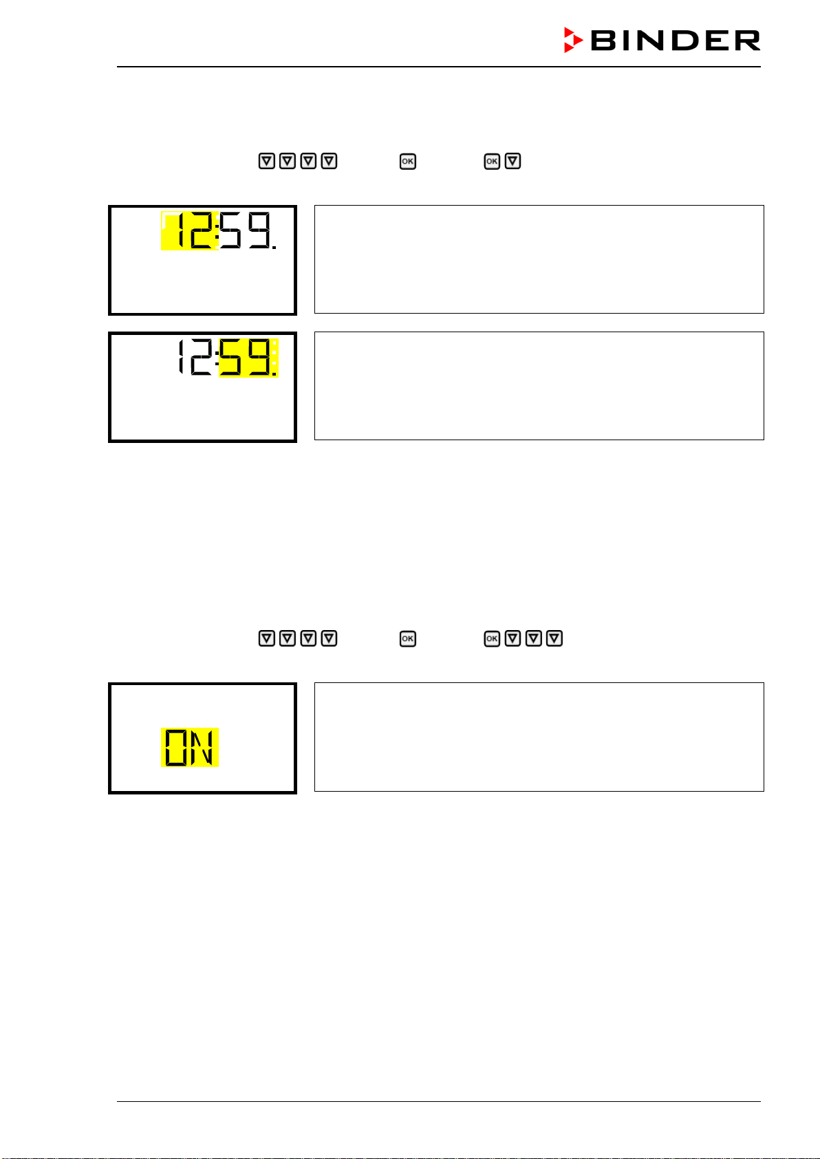
CB-S / CB-S-UL (E7) 06/2020 page 50/119
12.4 Setting the current time
Required access level: “Admin”. Following start-up of the chamber (chap. 6.3), it is “User”.
Path: Normal display Settings Chamber Time
Press the OK button to enable the setting.
Setting the time: hours
The current setting flashes. Enter the current hour with the arrow but-
tons.
Confirm the entry with the OK button.
Time
Setting the time: minutes
The current setting flashes. Enter the current minutes with the arrow
buttons.
Confirm the entry with the OK button.
Time
With the Back button you can go back to the “Chamber” submenu and, repeatedly pressing it, to Nor-
mal display.
12.5 Function “Language selection at restart”
If the function “Language selection at restart” is activated, menu language, date, time, and temperature
unit are checked with every startup of the chamber. At this occasion it is also possible to modify them with
“User” access level.
Required access level: “Admin”.
Path: Normal display Settings Chamber Language selection at restart
Press the OK button to enable the setting.
Function “Language selection at restart”
The current setting flashes. Use the arrow buttons to select between
ON and OFF.
Confirm the setting with the OK button.
Language sel. at restar
With the arrow-down button you can now change to the next parameter (chamber address).
With the Back button you can go back to the “Chamber” submenu and, repeatedly pressing it, to Nor-
mal display.
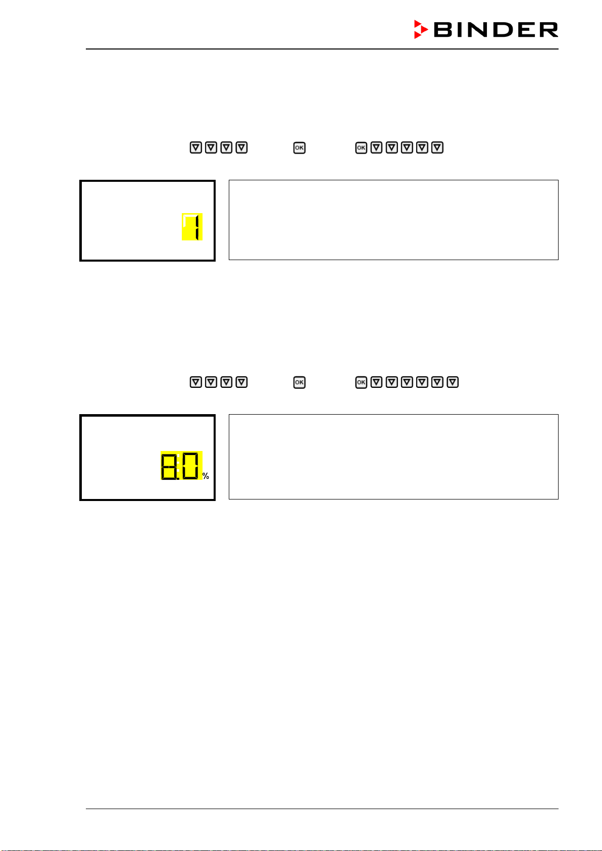
CB-S / CB-S-UL (E7) 06/2020 page 51/119
12.6 Setting the chamber address
This setting is required for the communication with the BINDER APT-COM™ 4 Multi Management Soft-
ware. The chamber address settings in the chamber controller and in the software must be identical.
Required access level: “Admin”.
Path: Normal display Settings Chamber Chamber address
Press the OK button to enable the setting.
Setting the chamber address
The current setting flashes. Enter the desired address with the arrow
buttons. Setting range: 1 up to 254
Confirm the entry with the OK button.
Chamber address
With the arrow-down button you can now change to the next parameter (display brightness).
With the Back button you can go back to the “Chamber” submenu and, repeatedly pressing it, to Nor-
mal display.
12.7 Display brightness
Required access level: “Admin”.
Path: Normal display Settings Chamber Brightness
Press the OK button to enable the setting.
Setting the display brightness
The current setting flashes. Enter the desired value with the arrow but-
tons. Setting range: 10% up to 100%
Confirm the entry with the OK button.
Brightness
With the arrow-down button you can now change to the next parameter (audible alarm, chap. 15.3).
With the Back button you can go back to the “Chamber” submenu and, repeatedly pressing it, to Nor-
mal display.
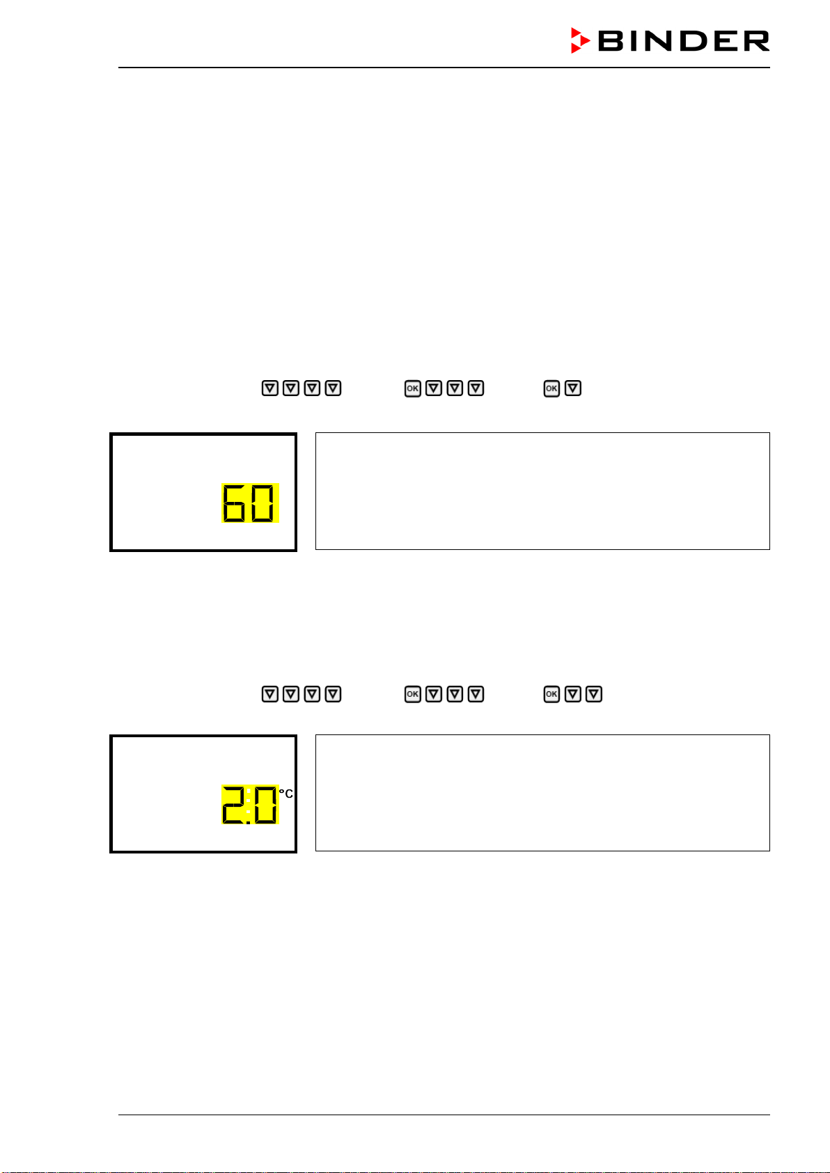
CB-S / CB-S-UL (E7) 06/2020 page 52/119
13. Tolerance range settings
In this menu you can define for temperature and CO
2
the deviation between the actual value and setpoint,
which that shall cause a tolerance range alarm. The entered value defines the limit of permitted devia-
tions from the set-point (exceeding and falling below). Reaching this limit triggers tolerance alarm.
In addition you can specify a delay time for this alarm.
If there are any actual values outside the tolerance range, after the configured alarm delay time the alarm
message “Temperature range” and / or “CO2 range” is displayed in Normal display (chap. 15.1). If the
alarm buzzer is activated (chap. 15.3) there is an audible alert.
This function only activates after the set-point has been reached once.
Required access level: “Admin”.
13.1 Setting the delay time for tolerance range alarm
Path: Normal display Settings Various Range alarm delay (min)
Press the OK button to enable the setting.
Setting the tolerance range alarm delay.
The current setting flashes. Use the arrow buttons to enter the de-
sired time after which the range alarm shall be triggered. Entry range: 1
up to 120 minutes.
Confirm the entry with the OK button.
Range alarm delay (mi
With the arrow-down button you can now change to the temperature tolerance range setting.
With the Back button you can go back to the “Various” submenu and, repeatedly pressing it, to Normal
display.
13.2 Setting the temperature tolerance range
Path: Normal display Settings Various Temperature range
Press the OK button to enable the setting.
Setting the temperature tolerance range
The current setting flashes. Enter the desired temperature range with
the arrow buttons. Entry range: 1.0 °C up to 10.0 °C
Confirm the entry with the OK button.
Temperature range
With the arrow-up button you can go back to the tolerance range alarm delay setting.
With the arrow-down button you can now change to the CO
2
tolerance range setting.
With the Back button you can go back to the “Various” submenu and, repeatedly pressing it, to Normal
display.
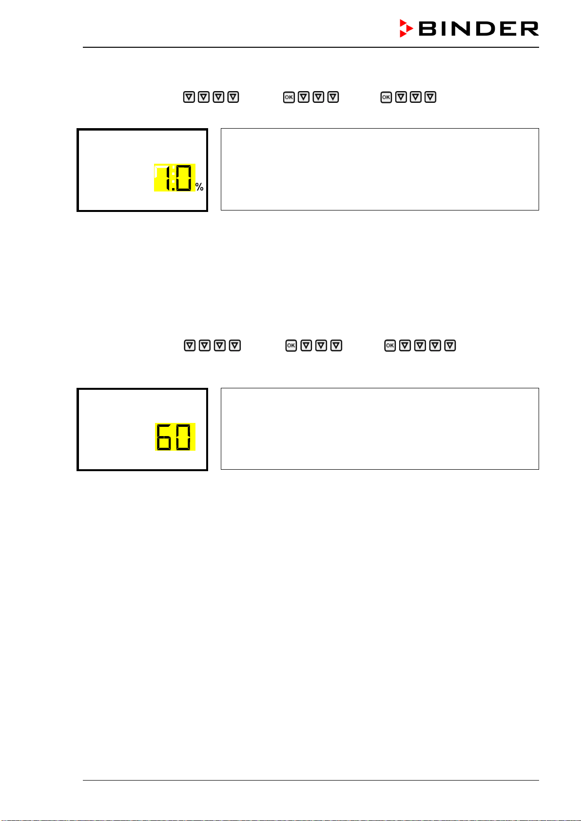
CB-S / CB-S-UL (E7) 06/2020 page 53/119
13.3 Setting the CO
2
tolerance range
Path: Normal display Settings Various CO2 range
Press the OK button to enable the setting.
Setting the CO
2
tolerance range
The current setting flashes. Enter the desired CO
2
range with the ar-
row buttons. Entry range: 1.0 vol.-% up to 10.0 vol.-%
Confirm the entry with the OK button.
CO2 range
With the arrow-up button you can go back to the temperature range setting
With the arrow-down button you can now change to the door open alarm delay setting.
With the Back button you can go back to the “Various” submenu and, repeatedly pressing it, to Normal
display.
13.4 Setting the delay time for door open alarm
Path: Normal display Settings Various Door alarm delay
(min)
Press the OK button to enable the setting.
Setting the door open alarm delay.
The current setting flashes. Use the arrow buttons to enter the de-
sired time after which the door alarm shall be triggered. Entry range: 1
up to 120 minutes.
Confirm the entry with the OK button.
Door alarm delay (min)
With the arrow-up button you can go back to the CO
2
tolerance range setting
With the arrow-down button you can now change to the humidity control setting.
With the Back button you can go back to the “Various” submenu and, repeatedly pressing it, to Normal
display.
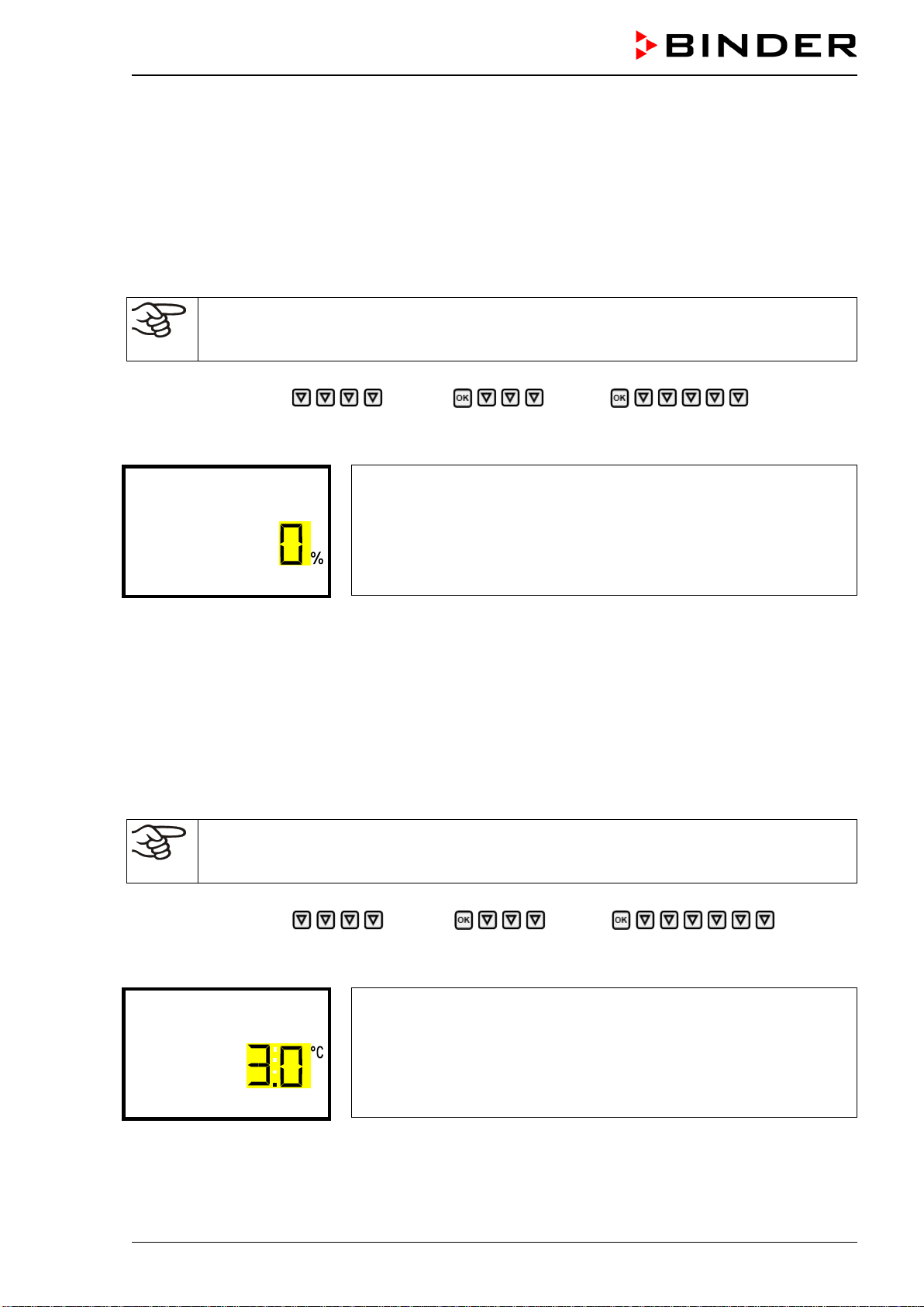
CB-S / CB-S-UL (E7) 06/2020 page 54/119
14. Chamber settings (for experienced users only)
14.1 Setting the humidity control
The humidifying system provides a maximum humidity of up to 95 % r.h. in the inner chamber, which
remains condensation-free. This performance assumes an average ambient temperature of +22 °C +/- 3
°C / 71.6 °F +/- 5.4 °F and a working temperature in the inner chamber of 37 °C / 98.6 °F.
Depending on the installation site and ambient temperature you can increase or decrease the humidity by
up to +/- 5 % r.h. if required. Factory setting: 0 % r.h.
If the ambient temperature deviates by more than +/- 5 °C from the values recommended by
the manufacturer, the conditions for maximum air humidity with condensation-free inner
chamber are no longer guaranteed. Contact BINDER Service for assistance.
Path: Normal display Settings Various Humidity con-
trol
Press the OK button to enable the setting.
Setting the humidity control
The current setting flashes. Enter the desired value with the arrow
buttons. Entry range: -5 % r.h. up to +5 % r.h.
Confirm the entry with the OK button.
Humidity control
With the arrow-up button you can change to the door open alarm delay setting (chap. 13.4).
With the arrow-down button you can now change to the door heating offset setting.
With the Back button you can go back to the “Various” submenu and, repeatedly pressing it, to Normal
display.
14.2 Setting the door heating offset
In unfavorable ambient conditions, condensation may occur in the door area. To avoid this, an Offset
value for the door heating can be set. Factory setting: 3.0 °C.
If the ambient temperature deviates by more than +/- 5 °C from the values recommended by
the manufacturer, the conditions for maximum air humidity with condensation-free inner
chamber are no longer guaranteed. Contact BINDER Service for assistance.
Path: Normal display Settings Various Doortemp.
offset
Press the OK button to enable the setting.
Setting the door temperature offset.
The current setting flashes. Enter the desired value with the arrow
buttons. Entry range: -5.0 °C up to +5.0 °C.
Confirm the entry with the OK button.
Doortemp. offset
With the arrow-up button you can go back to the humidity control setting.
With the Back button you can go back to the “Various” submenu and, repeatedly pressing it, to Normal
display.
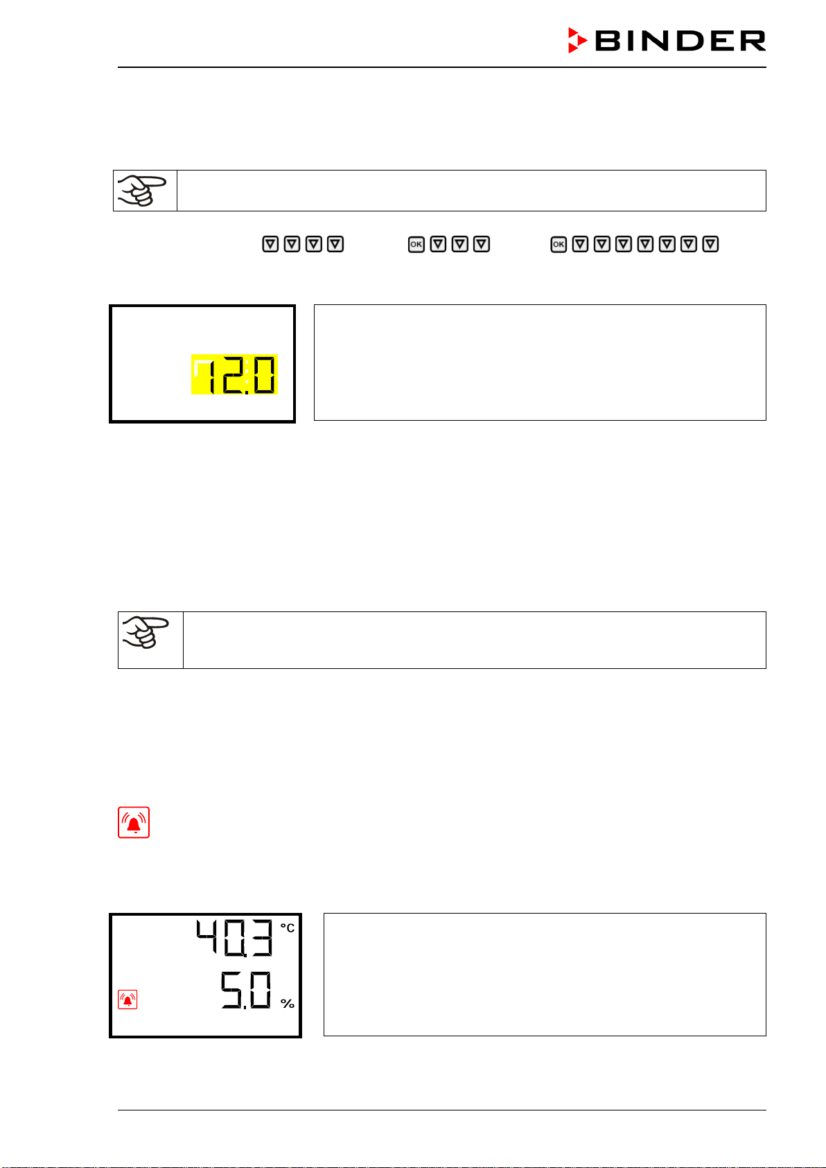
CB-S / CB-S-UL (E7) 06/2020 page 55/119
14.3 Adjusting the heating power – for BINDER Service only
Depending on the duration of the door opening, a heating power factor for humidity recovery time can be
adapted. Factory setting: 12.0.
This setting is intended for BINDER Service only!
Path: Normal display Settings Various Factor
humid. recovery
Press the OK button to enable the setting.
Setting the heating power factor for humidity recovery time.
The current setting flashes. Enter the desired factor with the arrow
buttons. Entry range: 0.0 to 100.0.
Confirm the entry with the OK button.
Factor humid. recover
With the arrow-up button you can go back to the door heating offset setting.
With the Back button you can go back to the “Various” submenu and, repeatedly pressing it, to Normal
display.
15. Notification and alarm functions
15.1 Alarm messages
WARNING: If customer should use a chamber running in non-supervised continuous opera-
tion, we strongly recommend in case of inclusion of irrecoverable specimen or samples to
split such specimen or samples and store them in at least two chambers, if this is feasible.
In the event of equipment failures, or when the temperature and / or CO
2
deviate from the set tolerance
range limits, optical and possibly acoustic alarm messages are given out via the controller. A zero-voltage
relay alarm output (9) (chap. 15.5) permits transmission of the alarm e.g., to a central monitoring system.
The alarm messages door open and leaving the tolerance range are emitted after a configurable delay
(chap. 13), the others immediately when the fault occurs. The tolerance range alarms are suppressed
after opening the chamber door or turning on the chamber until the corresponding setpoint is reached,
and then for the selected delay time.
In Normal display a text message indicates the alarm cause. The “collective alarm” icon flashes. If
the audible arm is activated, the buzzer sounds.
If more than one alarm signal is sent simultaneously, they are displayed in a cycle.
Press the OK button to confirm the alarm and mute the buzzer. If the alarm cause is still valid, the “col-
lective alarm” icon is lit.
Alarm indication (example: safety controller alarm)
Safety controller
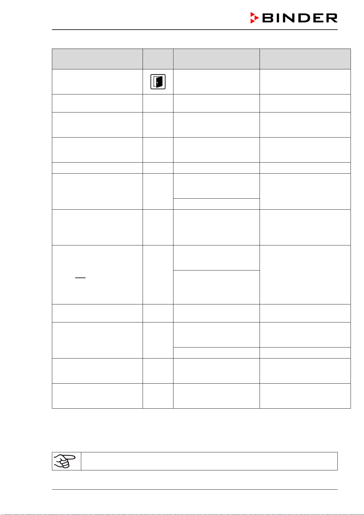
CB-S / CB-S-UL (E7) 06/2020 page 56/119
Alarm messages overview:
Condition Icon Alarm message
Moment of alarm message and
switching the zero-voltage
alarm relay output
Chamber door open
“Door open”
after configurable time
(chap. 13.4).
Factory setting: 1 minute
Setpoint of the safety controller
class 3.1 exceeded
“Safety controller” immediately
Tolerance range alarm: actual
temperature value exceeding
the tolerance range)
“Temperature range”
after configurable time
(chap. 13.1)
Factory setting: 10 minutes
Tolerance range alarm: actual
CO
2
value exceeding the tol-
erance range
“CO2 range”
after configurable time
(chap. 13.1)
Factory setting: 10 minutes
CO
2
pressure too low “CO2 pressure” immediately
Inner temperature sensor de-
fective. Control continues us-
ing the safety controller tem-
perature sensor.
Actual temperature value
display shows
“ – – – – ”
immediately
“Inner temp. sensor”
Failure of safety controller
temperature sensor
Messages alternating:
“Safety controller” and
“Safety control sensor”
immediately
Failure of inner temperature
sensor and safety controller
temperature sensor
Actual temperature value
display shows
“ – – – – “
immediately
Messages alternating:
“Inner temp. sensor”, “Safety
controller”, and “Safety con-
trol sensor”
Failure of temperature sensor
for door heating
“Door heating sensor” immediately
Failure of CO
2
sensor
Actual CO
2
value
display shows
“ – – – – ”
immediately
“CO2 sensor defective” after 1 minute
CO
2
sensor not connected
Actual CO
2
value
display shows
“ – – – – ”
immediately
Sterilization terminated prema-
turely after less than 6 hours:
Ineffective sterilization
“Sterilization failed” immediately
Press the OK button to confirm the alarm.
• Confirmation while the state of alarm persists: Only the buzzer is muted. The visual alarm message
continues to be displayed until the alarm condition is removed. Then it is reset automatically.
• Confirmation after the alarm has ended: The buzzer and the visual alarm message are rest together.
When operating the chamber without CO
2
gas connection, turn off CO
2
control (function
“CO2 off”, chap. 9) in order to avoid alarms of the CO
2
gas system.
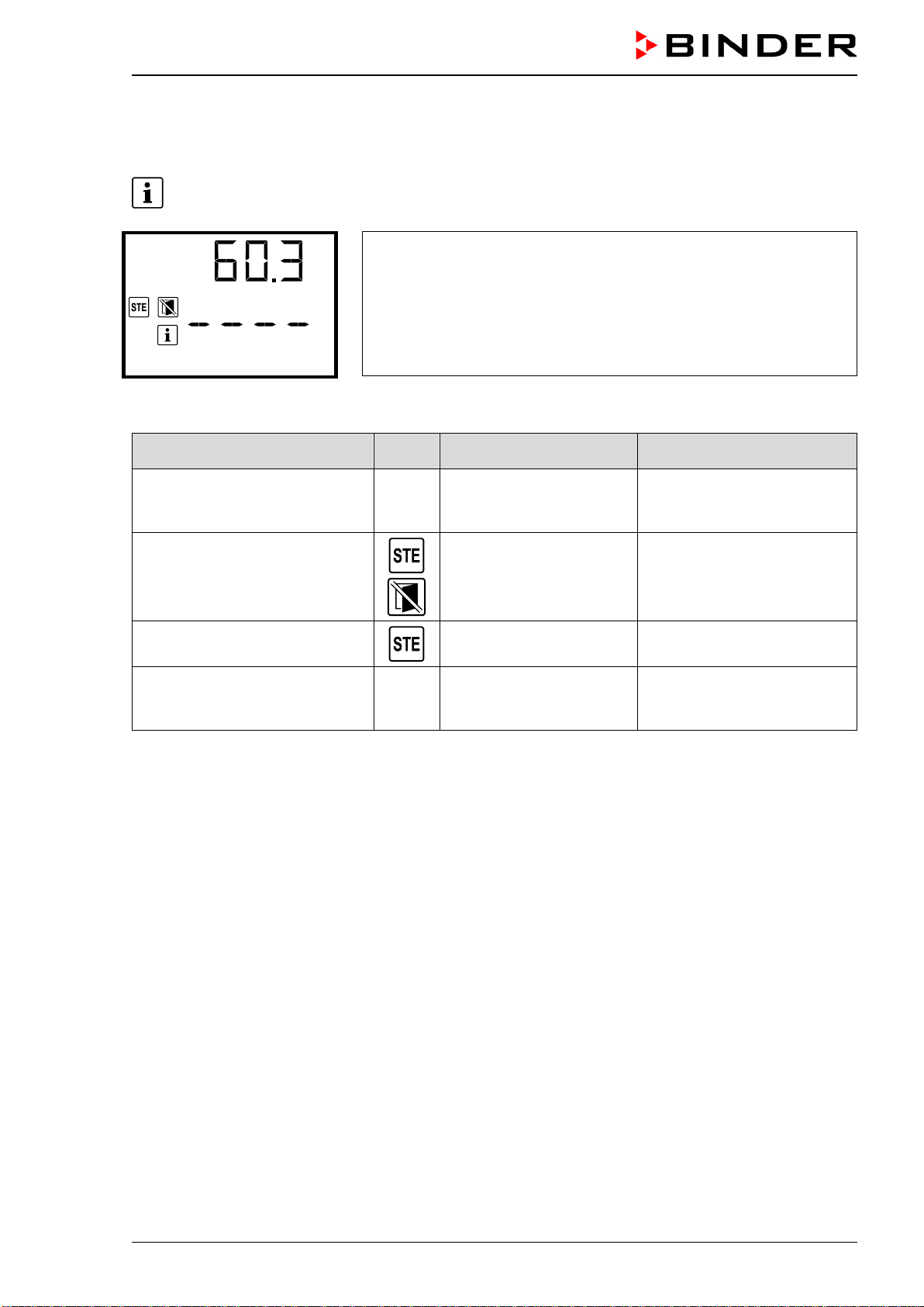
CB-S / CB-S-UL (E7) 06/2020 page 57/119
15.2 Information messages
Information messages provide information about the settings made or the current controller condition.
In Normal display a text message indicates the condition. The “Information” icon is lit.
Information message (example: sterilization running)
Sterilization
Information messages overview:
Condition Icon Information message
Moment of information
message
Trying to start sterilization cycle
while the CO
2
sensor still
plugged-in
“CO2 sensor plugged-in” Sterilization start
Sterilization is running
“Sterilization” During sterilization
Sterilization successfully com-
pleted
“Sterilization success”
After 6 hours
of sterilization cycle
Recommended maintenance
interval (one year of operation)
is over.
“Service due!”
Each week of operation after
maintenance interval is over.
Press the OK button to confirm the information message.
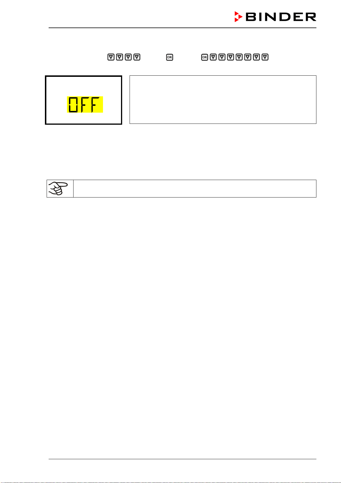
CB-S / CB-S-UL (E7) 06/2020 page 58/119
15.3 Activating / deactivating the audible alarm (alarm buzzer)
Path: Normal display Settings Chamber Audible alarm
Press the OK button to enable the setting.
Setting the audible alarm.
The current setting flashes. Use the arrow buttons to select between
ON and OFF.
Confirm the setting with the OK button.
Audible alarm
With the Back button you can go back to the “Chamber” submenu and, repeatedly pressing it, to Nor-
mal display.
15.4 Measures in case of alarm
Only qualified service personnel authorized by BINDER must perform repair.
Repaired chambers must comply with the BINDER quality standards.
15.4.1 Door open alarm
The open and closed position of the chamber door is controlled via the door contact switch. If the door is
open, the temperature and CO
2
controls turn off.
When the door is opened the alarm occurs after an adjustable delay time (chap. 13.4). Factory setting: 1
minute.
• Alarm message “Door open”, “collective alarm” icon
• Audible alarm: buzzer
• Switching the zero-voltage relay alarm output
Actions:
• Close the outer door.
• Use the OK button to turn off the buzzer even when the door is open.
• The alarm message is cancelled.
• The zero-voltage relay alarm output switches off.
15.4.2 Safety controller temperature alarm
The set temperature value (set point type “Limit” or “Offset”) was exceeded.
• Immediate alarm
• Alarm message “Safety controller”, “collective alarm” icon
• Audible alarm: buzzer
• Switching the zero-voltage relay alarm output.
CB-S / CB-S-UL (E7) 06/2020 page 59/119
Actions:
• Check whether the outer door was open for a long time or is not closed properly. Close the door if
necessary. With open door there can be additional door open alarm.
• Check the setting of the safety controller (chap. 11.2). The limit temperature should be at least 2 °C
above the temperature set point; the offset temperature should be ≥ 2 °C. If necessary, adjust the rele-
vant value.
• Check whether samples were inserted into the chamber that produce heat.
• Check the ambient conditions. The ambient temperature must be at least by 6 °C / 10.8 °F below the
temperature set point of the chamber. Protect the chamber from direct sunlight. Ensure sufficient venti-
lation around the installation location to prevent any buildup of heat in the chamber.
• Check whether the sterilization cycle was terminated prematurely and the chamber has not yet cooled
down.
• If these points do not reveal the source of the fault, it may be that the chamber is faulty. Please contact
BINDER Service.
15.4.3 Temperature tolerance range alarm (overtemperature / too low temperature)
The tolerance range alarm becomes valid only after the setpoint has been reached.
When the actual value leaves the tolerance range the alarm occurs after an adjustable delay time (chap.
13.1). Factory setting: 10 minutes.
• Alarm message “Temperature range”, “collective alarm” icon
• Audible alarm: buzzer
• Switching the zero-voltage relay alarm output
Actions:
• Factory setting for the temperature tolerance range is +/- 1.0 K. Modify the value if necessary (chap.
13.2).
• Use the displayed actual temperature value to verify in whether the tolerance range has been exceed-
ed (too warm) or fallen below (too cold).
Low temperature alarm:
• Check whether the outer door was open for a long time or is not closed properly. Close the door if
necessary. With open door there can be additional door open alarm.
• Check the door's seals for any damage. Replace any damaged seals.
Overtemperature alarm:
• Check whether samples were inserted into the chamber that produce heat. Reset the alarm with the
OK button.
• Check the ambient conditions. The ambient temperature must be at least by 6 °C / 10.8 °F below the
temperature set point of the chamber. Protect the chamber from direct sunlight. Ensure sufficient venti-
lation around the installation location to prevent any buildup of heat in the chamber.
• If these points do not reveal the source of the fault, it may be that the chamber is faulty. Please contact
BINDER Service.
• To decrease the temperature, proceed as follows: Turn off the chamber. Open both chamber doors for
approx. 5 minutes. Turn on the chamber again. You can restart normal operation as soon as the re-
quested values have equilibrated.
If the same alarm recurs, please contact BINDER Service.
CB-S / CB-S-UL (E7) 06/2020 page 60/119
15.4.4 CO
2
tolerance range alarm (CO
2
over/under concentration)
If CO
2
control has been deactivated (chap. 9.2), no alarms of the CO
2
gas system will be emit-
ted.
The tolerance range alarm becomes valid only after the setpoint has been reached.
When the actual value leaves the tolerance range the alarm occurs after an adjustable delay time (chap.
13.1). Factory setting: 10 minutes.
• Alarm message “CO2 range”, “collective alarm” icon
• Audible alarm: buzzer
• Switching the zero-voltage relay alarm output
Actions:
• Factory setting for the CO
2
tolerance range is +/- 1.0 vol.-%. Modify the value if necessary (chap. 13.3)
• Use the displayed actual CO
2
value to verify in whether the tolerance range has been exceeded or
fallen below.
CO
2
under concentration alarm:
• Check whether the outer door was open for a long time or is not closed properly. Close the door if
necessary. With open door there can be additional door open alarm.
• Check the door's seals for any damage. Replace any damaged seals.
• If these points do not reveal the source of the fault, it may be that the chamber is faulty. Please contact
BINDER Service.
CO
2
over concentration alarm:
• Open both chamber doors for approx. 30 seconds. Respect the precautions when working with CO
2
gas (chap. 1.8).
• Normal operation can be restarted, as soon as the requested values have been readjusted.
• Reset the alarm message.
If the same alarm recurs, please contact BINDER Service.
15.4.5 CO
2
pressure alarm
If CO
2
control has been deactivated (chap. 9.2), no alarms of the CO
2
gas system will be
emitted.
The CO
2
primary pressure at the intake valve is less than 0.3 bar / 4.4 psi below the ambient air pressure.
The alarm displays show a pressure drop of CO
2
admission below 0.3 bar / 4.4 psi. Check whether the
gas cylinder is open. CO
2
connection pressure is too low.
The alarm occurs immediately.
• Alarm message “CO2 pressure”, “collective alarm” icon.
• Audible alarm: buzzer
• Switching the zero-voltage relay alarm output
CB-S / CB-S-UL (E7) 06/2020 page 61/119
Actions:
• Check that you have set the pressure on the pressure reducer at 2.0 bar / 29 psi above the ambient
air pressure, and that all the valves are open for the gas supply.
• Where the CO
2
supply is a pressurized gas cylinder, check that the cylinder still contains sufficient
CO
2
. If necessary, replace the gas cylinder. Observe the precautions when handling gases and the
correct outlet pressure (chap. 4.4).
• When using central CO
2
supply, check whether the primary pressure is high enough.
• Check that the gas tube has no damage, kinks, blockages or soiling.
• Check when the gas filter was last replaced. Replace the gas filter every year to avoid it blocking. A
qualified service engineer should replace the gas filter.
• If these points do not reveal the source of the fault, it may be that the chamber is faulty. Please contact
BINDER Service.
The outlet pressure of the gas cylinder must be 2.0 bar / 29 psi above the ambient pressure.
NOTICE
Danger of damage by excessive outlet pressure > 2.5 bar / 36 psi.
Damage to the chamber.
∅ The outlet pressure must NOT exceed the indicated value of 2.5 bar / 36 psi.
Before connecting, check the outlet pressure on the pressure reducer of the cylinder.
Adjust the outlet pressure to 2.0 bar / 29 psi above the ambient pressure.
The recovery times of the gas concentrations inside the chamber following the door being opened, which
are indicated in the technical data (chap. 26.4), refer to a connection pressure of 2.0 bar / 29 psi. De-
creasing supply pressure down to the alarm point of 0.3 bar / 4.4 psi results in longer recovery times.
Check the pressure displays of your gas supply. If very short recovery times are required or the door is
opened frequently, replace the gas cylinders promptly when the pressure decreases below 2.0 bar / 29
psi.
15.4.6 Power failure alarm
• No alarm message (display is off)
• Audible alarm (buzzer): immediately
• Switching the zero-voltage relay alarm output.
WARNING: If customer should use a chamber running in non-supervised continuous opera-
tion, we strongly recommend in case of inclusion of irrecoverable specimen or samples to
split such specimen or samples and store them in at least two chambers, if this is feasible.

CB-S / CB-S-UL (E7) 06/2020 page 62/119
15.4.7 Alarms referring to temperature sensor failures
The alarms occur immediately.
• Alarm messages corresponding to the individual alarm cause, “collective alarm” icon
• Audible alarm: buzzer (intermittent sound)
• Switching the zero-voltage relay alarm output
• A sensor fault alarm display takes priority over all other operational displays and alarm signals on the
controller.
Actions:
• Turn off the chamber.
• If necessary, clean and disinfect the chamber. Automatic sterilization is not possible with this fault.
• Please contact BINDER Service.
Failure of inner temperature sensor
• Actual temperature value display shows “ – – – – ”
• Alarm message “Inner temp. sensor”
Temperature control continues using the safety controller temperature sensor.
Failure of safety controller temperature sensor
• Alarm messages “Safety controller” and “Safety control sensor” alternating, “collective alarm” icon
All heating elements turn off.
Failure of inner temperature sensor and safety controller temperature sensor
• Actual temperature value display shows “ – – – – ”
• Alarm messages “Inner temp. sensor”, “Safety controller”, and “Safety control sensor” alternating “col-
lective alarm” icon
All heating elements turn off.
Failure of temperature sensor for door heating
• Alarm message “Door heating sensor”, “collective alarm” icon
The door heating turns off.

CB-S / CB-S-UL (E7) 06/2020 page 63/119
15.4.8 Alarms referring to CO
2
sensor failure
If CO
2
control has been deactivated (chap. 9.2), no alarms of the CO
2
gas system will be
emitted.
The alarms occur immediately.
Failure of CO
2
sensor
• Actual CO
2
value display shows “ – – – – ”
• Alarm message “CO2 sensor defective”, “collective alarm” icon
Actions:
• Turn off the chamber.
• Remove the sensor (chap. 4.2), replace it if necessary.
• If necessary, clean, disinfect and sterilize the chamber before restarting it
• Please contact BINDER Service.
CO
2
sensor not connected
• Actual CO
2
value display shows “ – – – – ”
Actions:
• Turn off the chamber.
• Connect the sensor (chap. 4.2.1)
15.4.9 Alarm on ineffective sterilization
The sterilization cycle was terminated prematurely after less than 6 hours (chap. 23.4.1)
• Alarm message “Sterilization failed”, “collective alarm” icon
Actions:
• Repeat the sterilization, if necessary (chap. 23.3).

CB-S / CB-S-UL (E7) 06/2020 page 64/119
15.5 Zero-voltage relay alarm output
Collective alarm output via the zero-voltage relay alarm contact
The chamber is equipped at the rear with a zero-voltage relay output (13) for temperature and CO
2
, which
permits the transmission of alarms to an external monitoring system in order to monitor and record the
alarm signals. A DIN socket (13) serves to establish this connection.
The zero-voltage relay alarm output switches for all alarm instances and in case of a power failure.
Depending on the alarm cause, the state of alarm is triggered immediately or after an adjustable time
(chap. 15.1). With the state of alarm, the “collective alarm” icon flashes on the controller display, a text
message indicates the alarm cause, and the buzzer sounds if the acoustic alarm has been activated. The
zero-voltage relay alarm contact switches without any delay.
ALARME
C = Pin 1 (Pole)
NC = Pin 2 (Break relay)
NO = Pin 3 (Make contact)
Figure 15: Zero-voltage contacts circuit diagram and pin allocation of DIN socket (13)
In case of no alarm, contact 1 (C) closes with contact 3 (NO).
Closing contact 1 (C) with contact 2 (NC) switches the zero-voltage relay alarm output
Maximum loading capacity of the switching contacts: 24V AC/DC – 2.5 Amp.
DANGER
Electrical hazard through overload of switching contacts.
Deadly electric shock. Damage to switching contacts and connection socket.
∅ Do NOT exceed the maximum switching load of 24V AC/DC – 2.5A.
∅ Do NOT connect any devices with a higher loading capacity.
The alarm message on the controller display remains displayed during transmission of an alarm via the
zero-voltage relay alarm output. As soon as the cause of the alarm is rectified, or the alarm message has
been reset, the alarm transmission via the zero-voltage relay outputs is reset together with the alarm
message on the controller display.
In case of power failure, transmission of the alarm via zero-voltage relay outputs remains active for the
duration of the power failure. When power supply returns, contact 1 (C) closes automatically with contact
3 (NO).
Connection to an external monitoring system
To ensure short-circuit-proof alarm monitoring that will trigger the alarm when the chamber connection to
an external alarm monitor is interrupted, connect the external alarm monitoring system to the chamber via
the contacts 1 (C) and 3 (NO). In this case, power failure will also trigger the alarm.
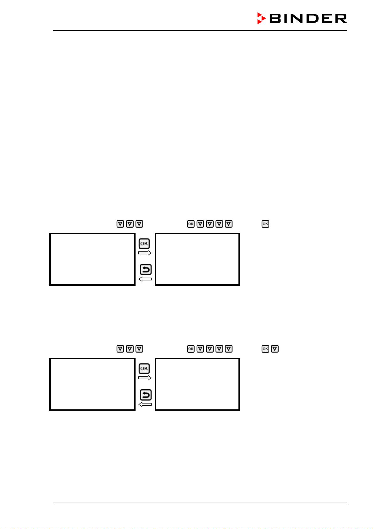
CB-S / CB-S-UL (E7) 06/2020 page 65/119
16. Ethernet network settings
The settings of the “Ethernet” submenu are used for networking chambers with an Ethernet interface,
e.g. to connect them with BINDER’s APT-COM™ 4 Multi Management Software (option, chap. 20.4).
16.1 Showing the network settings
Required access level: “User”.
The “Ethernet” submenu offers to subsequently or individually access the following information:
• MAC address
• IP address
• Subnet mask
• Standard gateway
• DNS server address
• DNS chamber name
16.1.1 Showing the chamber‘s MAC address
Path: Normal display Chamber info Ethernet MAC address
Display of the MAC address (exam-
ple)
Toggle forth and back with the Back
button and the OK button.
MAC address
00:00:00:00:00:00
With the arrow-down button you can now change to the next parameter (IP address).
With the Back button you can go back to the “Ethernet” submenu and, repeatedly pressing it, to Normal
display.
16.1.2 Showing the IP address
Path: Normal display Chamber info Ethernet IP address
Display of the IP address (example)
Toggle forth and back with the Back
button and the OK button.
IP address
0.0.0.0
With the arrow-down button you can now change to the next parameter (subnet mask).
With the Back button you can go back to the “Ethernet” submenu and, repeatedly pressing it, to Normal
display.
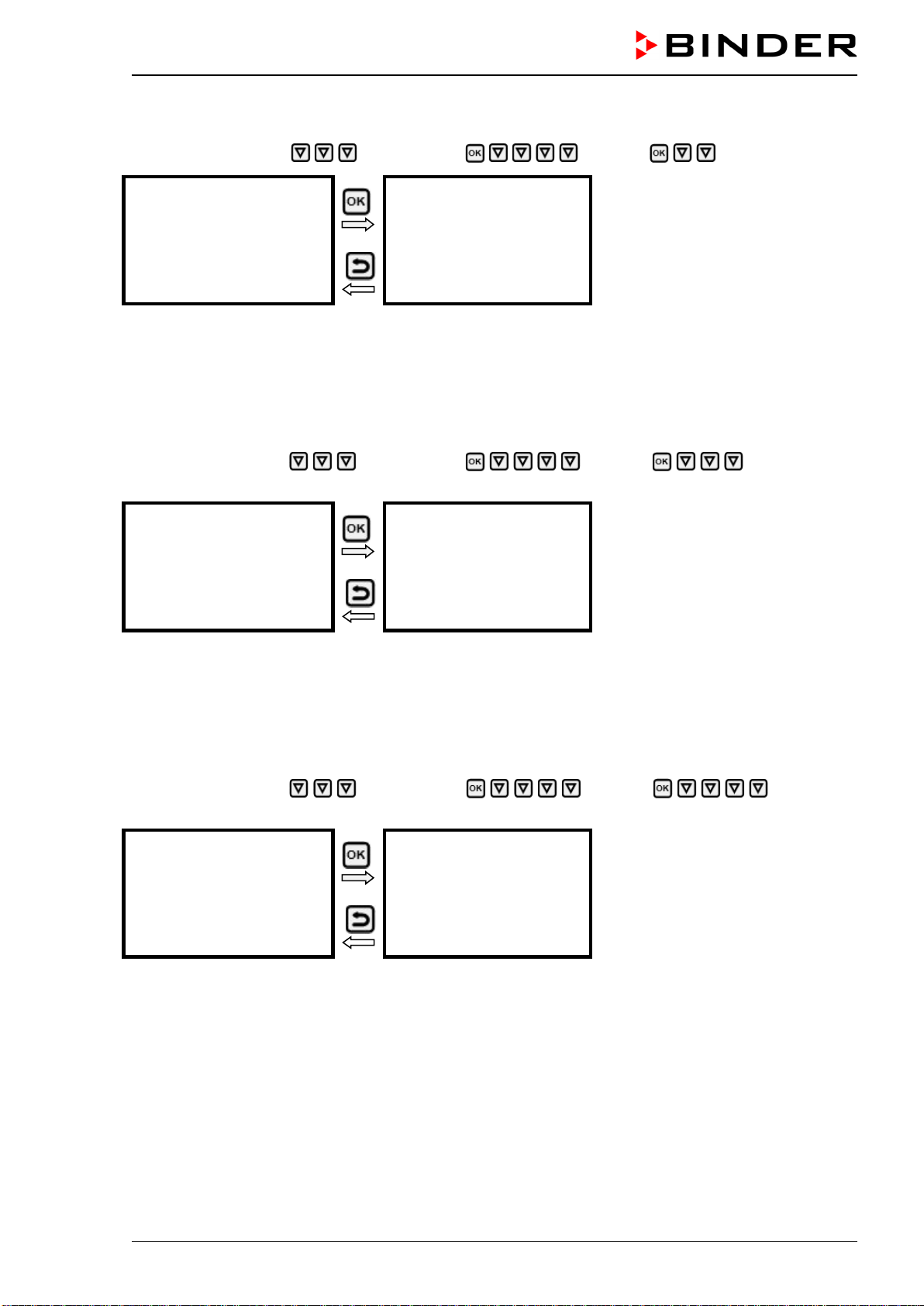
CB-S / CB-S-UL (E7) 06/2020 page 66/119
16.1.3 Showing the subnet mask
Path: Normal display Chamber info Ethernet Subnet mask
Display of the subnet mask (exam-
ple)
Toggle forth and back with the Back
button and the OK button.
Subnet mask
0.0.0.0
With the arrow-down button you can now change to the next parameter (standard gateway).
With the Back button you can go back to the “Ethernet” submenu and, repeatedly pressing it, to Normal
display.
16.1.4 Showing the standard gateway
Path: Normal display Chamber info Ethernet Standard gate-
way
Display of the standard gateway
(example)
Toggle forth and back with the Back
button and the OK button.
Standard gateway
0.0.0.0
With the arrow-down button you can now change to the next parameter (DNS server address).
With the Back button you can go back to the “Ethernet” submenu and, repeatedly pressing it, to Normal
display.
16.1.5 Showing the DNS server address
Path: Normal display Chamber info Ethernet DNS server
address
Display of the DNS server address
(example)
Toggle forth and back with the Back
button and the OK button.
DNS server address
0.0.0.0
With the arrow-down button you can now change to the next parameter (DNS chamber name).
With the Back button you can go back to the “Ethernet” submenu and, repeatedly pressing it, to Normal
display.
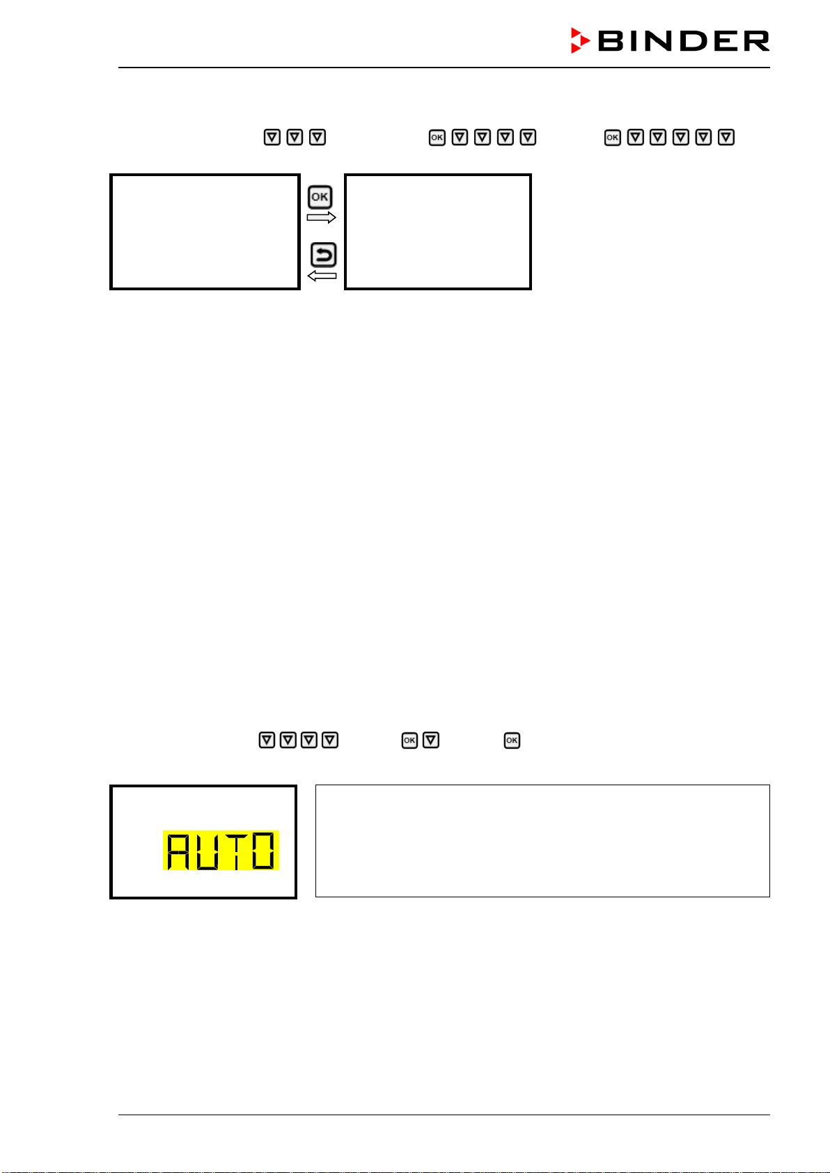
CB-S / CB-S-UL (E7) 06/2020 page 67/119
16.1.6 Showing the DNS chamber name
Path: Normal display Chamber info Ethernet DNS
chamber name
Display of the DNS chamber name
(example)
Toggle forth and back with the Back
button and the OK button.
DNS chamber name
BinderRD4-000cd80a281
With the Back button you can go back to the “Ethernet” submenu and, repeatedly pressing it, to Normal
display.
16.2 Changing the configuration of the network settings
Required access level: “Admin”.
The “Ethernet” submenu offers to subsequently or individually access the following settings:
• Selecting the type of assignment (automatic or manual) of the IP address, chap. 16.2.1
If automatic IP address assignment has been selected:
• Selecting the type of assignment (automatic or manual) of the DNS server address, chap. 16.2.2
If manual IP address assignment has been selected:
• Assigning the IP address, chap. 16.2.3
• Assigning the subnet mask, chap. 16.2.4
• Assigning the standard gateway, chap. 16.2.5
If manual IP address assignment or manual DNS server address assignment has been selected:
• Assigning the DNS server address, chap. 16.2.6
16.2.1 Selecting the type of IP address assignment (automatic / manual)
Path: Normal display Settings Ethernet IP address assignment
Press the OK button to enable the setting
Selection of the type of assignment of the IP address.
The current setting flashes. Use the arrow buttons to select between
AUTO (automatic) and MANU (manual).
Confirm the setting with the OK button.
IP address assignment
With the arrow-down button you can now change to the next parameter.
• If manual IP address assignment has been selected: assign the IP address (chap. 16.2.3)
• If automatic IP address assignment has been selected: select the type of assignment of the DNS
server address (chap. 16.2.2).
With the Back button you can go back to the “Ethernet” submenu and, repeatedly pressing it, to Normal
display.
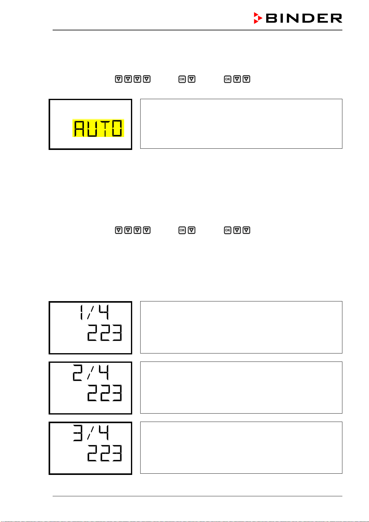
CB-S / CB-S-UL (E7) 06/2020 page 68/119
16.2.2 Selecting the type of assignment of the DNS server address (automatic / manual)
Access to this function is possible only if automatic IP address assignment has been selected (chap.
16.2.1).
Path: Normal display Settings Ethernet DNS server
Press the OK button to enable the setting.
Selection of the type of assignment of the DNS server address.
The current setting flashes. Use the arrow buttons to select between
AUTO (automatic) and MANU (manual).
Confirm the setting with the OK button.
DNS server
If manual assignment of the DNS server address has been selected, you can now change with the arrow-
down button to assign the DNS server address (chap. 16.2.6).
With the Back button you can go back to the “Ethernet” submenu and, repeatedly pressing it, to Normal
display.
16.2.3 Assigning the IP address
Access to this function is possible only if manual IP address assignment has been selected (chap. 16.2.1)
Path: Normal display Settings Ethernet IP address
Press the OK button to enable the setting.
The IP address entry is done in four steps, corresponding to the number sections: (1).(2).(3).(4)
Principle of entry:
• Use the OK button to select the desired section of the IP address 1/4, 2/4, 3/4, 4/4 in the upper dis-
play line
• Use the Arrow buttons to enter the value for the selected section of the IP address
IP address assignment (sample values).
The first section of the IP address is shown.
Enter the desired value with
the arrow buttons.
Use the OK button to confirm the entry and proceed to the second sec-
tion of the IP address.
IP address
IP address assignment (sample values).
The second section of the IP address is shown. Enter the desired value
with the arrow buttons.
Use the OK button to confirm the entry and proceed to the third
section
of the IP address.
IP address
IP address assignment (sample values).
The third section of the IP address is shown. Enter the desired value
with the arrow buttons.
Use the OK button to confirm the entry and proceed to the last section
of the IP address.
IP address
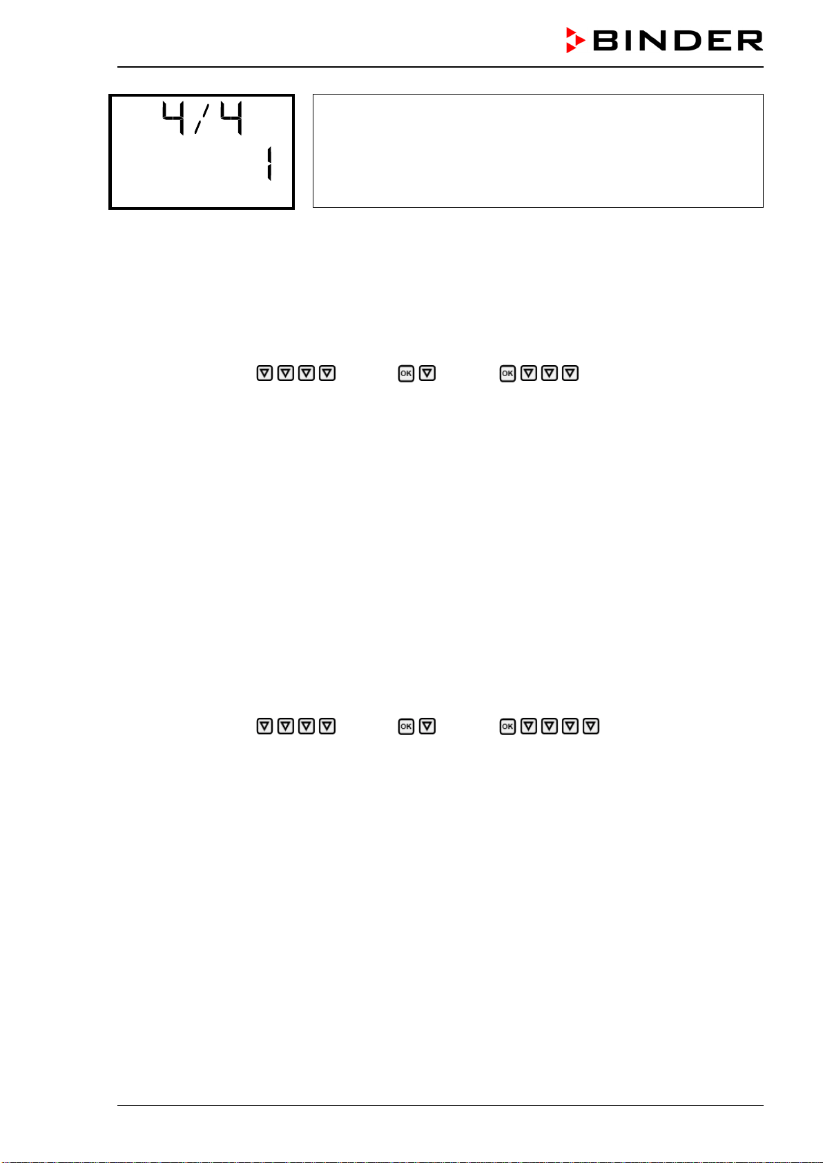
CB-S / CB-S-UL (E7) 06/2020 page 69/119
IP address assignment (sample values).
The forth section of the IP address is shown. Enter the desired value
with the arrow buttons.
Confirm the setting with the OK button.
IP address
With the arrow-down button you can now change to the enter the subnet mask.
With the Back button you can go back to the “Ethernet” submenu and, repeatedly pressing it, to Normal
display.
16.2.4 Setting the subnet mask
Access to this function is possible only if manual IP address assignment has been selected (chap. 16.2.1)
Path: Normal display Settings Ethernet Subnet mask
Press the OK button to enable the setting.
The subnet mask entry is done in four steps, corresponding to the number sections: (1).(2).(3).(4)
Principle of entry:
• Use the OK button to select the desired section of the subnet mask 1/4, 2/4, 3/4, 4/4 in the upper
display line
• Use the Arrow buttons to enter the value for the selected section of the subnet mask
For details please refer to the description of the similar procedure in chap. 16.2.3 “Assigning the IP ad-
dress”.
With the arrow-down button you can now change to the enter the standard gateway.
With the Back button you can go back to the “Ethernet” submenu and, repeatedly pressing it, to Normal
display.
16.2.5 Setting the standard gateway
Access to this function is possible only if manual IP address assignment has been selected (chap. 16.2.1)
Path: Normal display Settings Ethernet Standard gateway
Press the OK button to enable the setting.
The standard gateway entry is done in four steps, corresponding to the number sections: (1).(2).(3).(4)
Principle of entry:
• Use the OK button to select the desired section of the standard gateway 1/4, 2/4, 3/4, 4/4 in the upper
display line
• Use the Arrow buttons to enter the value for the selected section of the standard gateway
• For details please refer to the description of the similar procedure in chap. 16.2.3 “Assigning the IP
address”.
With the arrow-down button you can now change to the assign the DNS server address.
With the Back button you can go back to the “Ethernet” submenu and, repeatedly pressing it, to Normal
display.

CB-S / CB-S-UL (E7) 06/2020 page 70/119
16.2.6 Assigning the DNS server address
Access to this function is possible if manual IP address assignment (chap. 16.2.1) or manual DNS server
address assignment (chap. 16.2.2) has been selected.
With manual IP address assignment:
Path: Normal display Settings Ethernet DNS server address
With manual DNS server address assignment:
Path: Normal display Settings Ethernet DNS server address
Press the OK button to enable the setting.
The DNS server address entry is done in four steps, corresponding to the number sections: (1).(2).(3).(4)
Principle of entry:
• Use the OK button to select the desired section of the DNS server address 1/4, 2/4, 3/4, 4/4 in the
upper display line
• Use the Arrow buttons to enter the value for the selected section of the DNS server address
• For details please refer to the description of the similar procedure in chap. 16.2.3 “Assigning the IP
address”.
With the Back button you can go back to the “Ethernet” submenu and, repeatedly pressing it, to Normal
display.
17. Data recorder
An internal data recorder saves chamber data and events in three data sets.
With the export function “Export recorder data” (chap. 18.3) you can save the three data sets via the USB
interface to USB stick. They are issued in the selected language as a spreadsheet with the file extension
“.csv” and can be further processed in the desired program. The data is unencrypted. Always the entire
data memory is read out.
17.1 Recorded data
All data is given out in tabular form. The headlines of the values “number”, “date”, and “time” are given out
in the selected language, all other information in English.
• Chamber data for the user “DL1”
Tabular representation of the actual temperature and CO
2
values together with the date and time, ac-
cording to the set storage rate (chap. 17.3). Temperature values are always given out in °C.
• Chamber data for BINDER Service “DL2”
This data is intended for use by BINDER Service. It also contains information from the self-test func-
tion. The storage rate is fix (1 minute). Temperature values are always given out in °C.
• Event list
Messages regarding the controller and data memory as well as the alarm messages together with the
date and time:
• Firmware update done
• “New config (USB)”: New configuration uploaded via USB
• “Data recorder cleared “ Data recorder and event list deleted via setup program
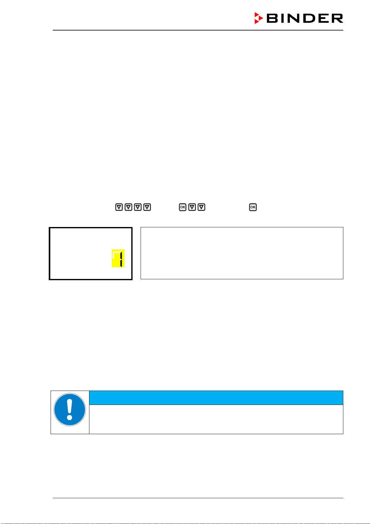
CB-S / CB-S-UL (E7) 06/2020 page 71/119
• Other event messages according to existing alarms
• The moment of switching the alarm state on and off is indicated under “On/Off”.
17.2 Storage capacity
The storage capacity of the data recorder depends on the number of entries.
• DL1 = 110.000 entries (equaling 76 days with a storage rate of 1 minute, setting see chap. 17.3)
• DL2 = 27.000 entries (equaling 18 days with a fix storage rate of 1 minute)
• Event list: 200 events
The shorter the set storage rate, the closer are the stored measuring points, the more precise, but also
shorter is the documented period.
Once the storage capacity of the data recorder is reached, overwriting of the oldest values begins.
17.3 Setting the storage rate for the “DL1” recorder data
Required access level: “Admin”.
Path: Normal display Settings Data recorder Storage interval
Press the OK button to enable the setting.
Function “Storage interval”.
The current setting flashes. Use the arrow buttons to enter the desired
storage interval. Setting range: 1 minute to 60 minutes.
Press the OK button to confirm the setting.
Storage interval
With the Back button you can go back to the “Data recorder” submenu and, repeatedly pressing it, to
Normal display.
17.4 Deleting the data recorder
When importing a configuration via USB stick (chap. 18.2) and when loading a new firmware version by
BINDER service, the entire data memory is deleted.
BINDER service can also install the configuration by means of a setup program without deleting the data.
Regardless of this, BINDER Service can delete the data via a setup program.
Loading a new configuration via USB-Stick leads to deleting the data recorder.
HINWEIS
Danger of information loss when loading a new configuration.
Data loss.
Backup data on the USB stick prior to loading a new configuration.
CB-S / CB-S-UL (E7) 06/2020 page 72/119
18. USB menu: Data transfer via USB interface
A USB interface for data transfer via USB stick is located in the instrument box (the second micro USB
interface is only used by the manufacturer).
The controller offers an import function and three export functions through the USB interface:
Import function (chap. 18.2):
• Configuration data in file “KONF380.set”
Export functions (chap. 18.3):
• Configuration data in file “KONF380.set”
• Recorder data
- DL1 (chamber data for the user): “DL1_[MAC address of the chamber].csv”
- DL2 (chamber data for BINDER Service): “DL2_[ MAC address of the chamber].csv”
- Event list: “EvList_[MAC address of the chamber].csv”
For detailed information on the file content see chap. 17.1.
• Service data
The "Service" folder is created on the USB stick and can be sent to BINDER Service. In addition to the
configuration and recorder data, it contains further service-relevant information.
18.1 Connecting the USB stick
Connect the USB stick to the interface located in the triangular instrument panel.
Connect only USB sticks to the USB interface.
After inserting the USB stick, the initial function “Import configuration” is displayed.
As long as the USB stick is connected, only the functions for data transfer are available. Other controller
functions are only available after removing the USB stick.

CB-S / CB-S-UL (E7) 06/2020 page 73/119
18.2 Import function
Required access level: “Admin”.
Function “Import configuration”.
To import configuration data from the USB stick, press the OK button.
Import configuration
With the arrow-down button you can now change to the setting of the “Export configuration” function.
18.3 Export functions
Required access level: any user
Function “Export configuration”.
To write the configuration data from the controller to the USB stick,
press the OK button.
Export configuration
With the arrow-down button you can now change to the next function.
Function “Export recorder data”.
To write the recorder
data from the controller to the USB stick, press the
OK button.
Export recorder data
With the arrow-down button you can now change to the next function.
Function “Export service data”.
To write the chamber
data from the controller to the USB stick, press the
OK button.
Export service data
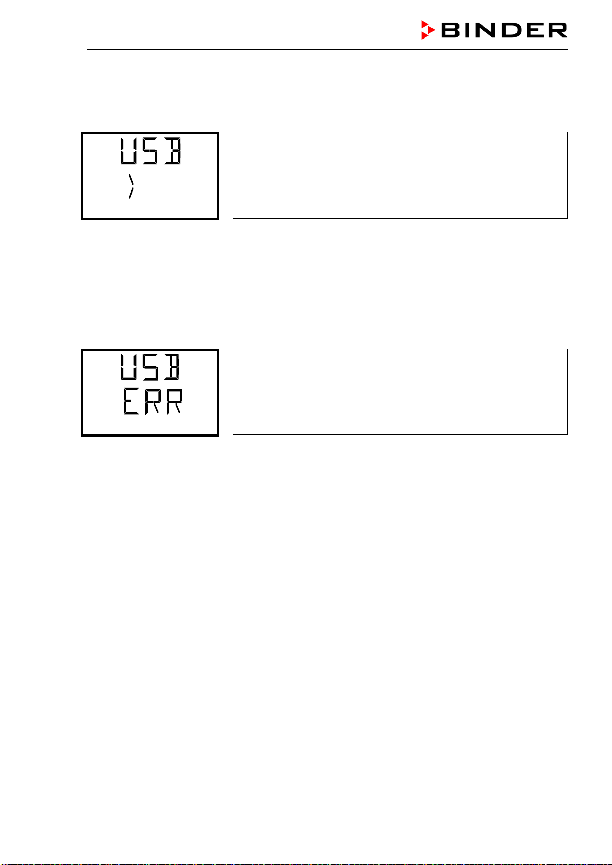
CB-S / CB-S-UL (E7) 06/2020 page 74/119
18.4 Ongoing data transfer
A moving arrow symbol indicates the progress of the data transfer.
Example:
Data recording is running.
Export service data
Attention! Danger of data loss! Do not disconnect the USB stick from the device during ongoing data
transfer!
After successful transfer, the controller shows again the initial function “Import configuration”.
18.5 Error during data transmission
In the event of an error, the message ERR (error) is displayed.
Read error (example).
Import configuration.
18.6 Removing the USB stick
Logging off the USB stick is not possible / required.
Be sure that no data recording is running (chap. 18.4).
After removing the USB stick, the controller is back in the same menu as before when connecting the
USB stick.
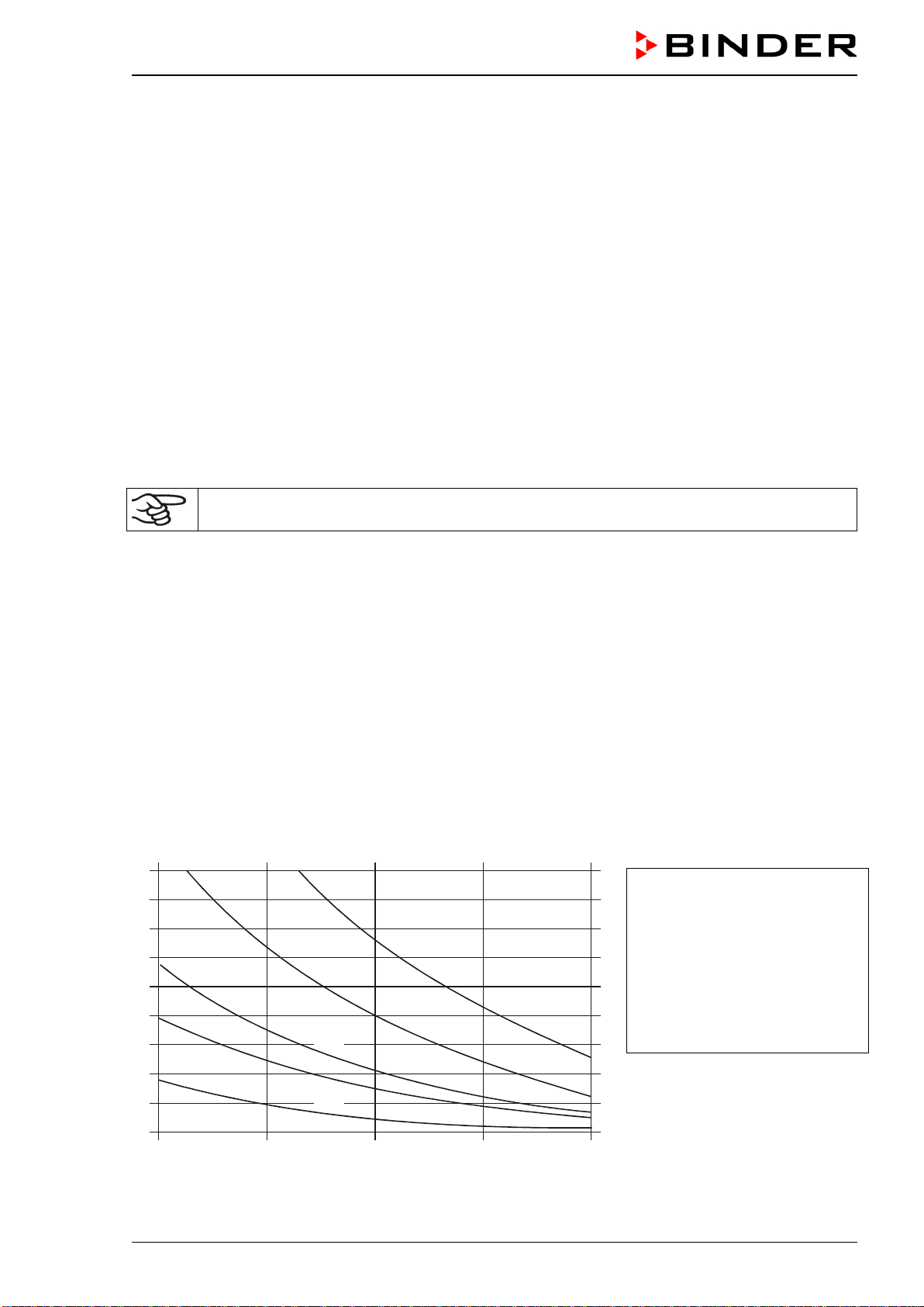
CB-S / CB-S-UL (E7) 06/2020 page 75/119
19. Reference measurements
You can take reference measurements of the temperature and CO
2
via the silicone measuring port (8)
located the inner glass door. Reference temperature measurements always take place under equilibrated
conditions with both doors closed.
19.1 CO
2
reference measuring
There are three possibilities to perform CO
2
test measurements between the recommended annual
maintenance procedures. To test the CO
2
concentration inside an incubator, see chapters 19.1.1 to
19.1.3.
19.1.1 Measuring the CO
2
concentration indirectly via the pH of the cell medium
By using the indirect determination of CO
2
concentration via the pH-value of the nutrient, it is possible to
check the CO
2
concentration inside the chamber. This is a simple method to test the correct CO
2
concen-
tration without any special CO
2
measuring equipment. You need only use an accurate pH indicator or a
pH-measuring electrode, which are standard equipment in cell culture laboratories.
This method is not suitable for calibrating the BINDER FPI sensor system.
This method is based on the acid base equilibrium of the buffer system in the culture media.
NaHCO
3
buffers the common media. From the pH value of the medium, it is possible to conclude its CO
2
concentration. Figure 16 shows the relationship between CO
2
concentration in vol.-% and the pH of dif-
ferent NaHCO
3
buffered media.
Recommended procedure:
• Incubate an empty sample with medium for 1/2 day under the same conditions as the cells. You can
perform the incubation in a cell culture bottle or in a 50 ml Falcon tube with open lid.
• After gassing, remove the empty sample from the incubator and within 5 minutes measure the pH-
value with a glass electrode.
During the measurement, the medium should have the least possible surface contact with the ambient
air, so that the CO
2
can evaporate only slightly. A significant downward movement will happen only af-
ter 5 minutes, permitting sufficient time for measurement.
• In addition, you can of course use pH-test strips (pH range 6 to 8, non-bleeding).
4
6
8
10
12
14
16
18
2
3,70 g/l NaHCO
3
2,20 g/l NaHCO
3
0,85 g/l NaHCO
3
6.8 7.0
7.2
7.4
7.6
Value pH
Vol.% CO
2
0,35 g/l NaHCO
3
1,20 g/l NaHCO
3
Trade names of common media:
DMEM
BME
MEM
Medium 199
Mc Coy
F10
F12
NaHCO
3
[g/l]
3.70
2.20
2.20
2.20
2.20
1.20
1.20
Figure 16: Value pH of NaHCO
3
buffered media as a function of the CO
2
concentration:
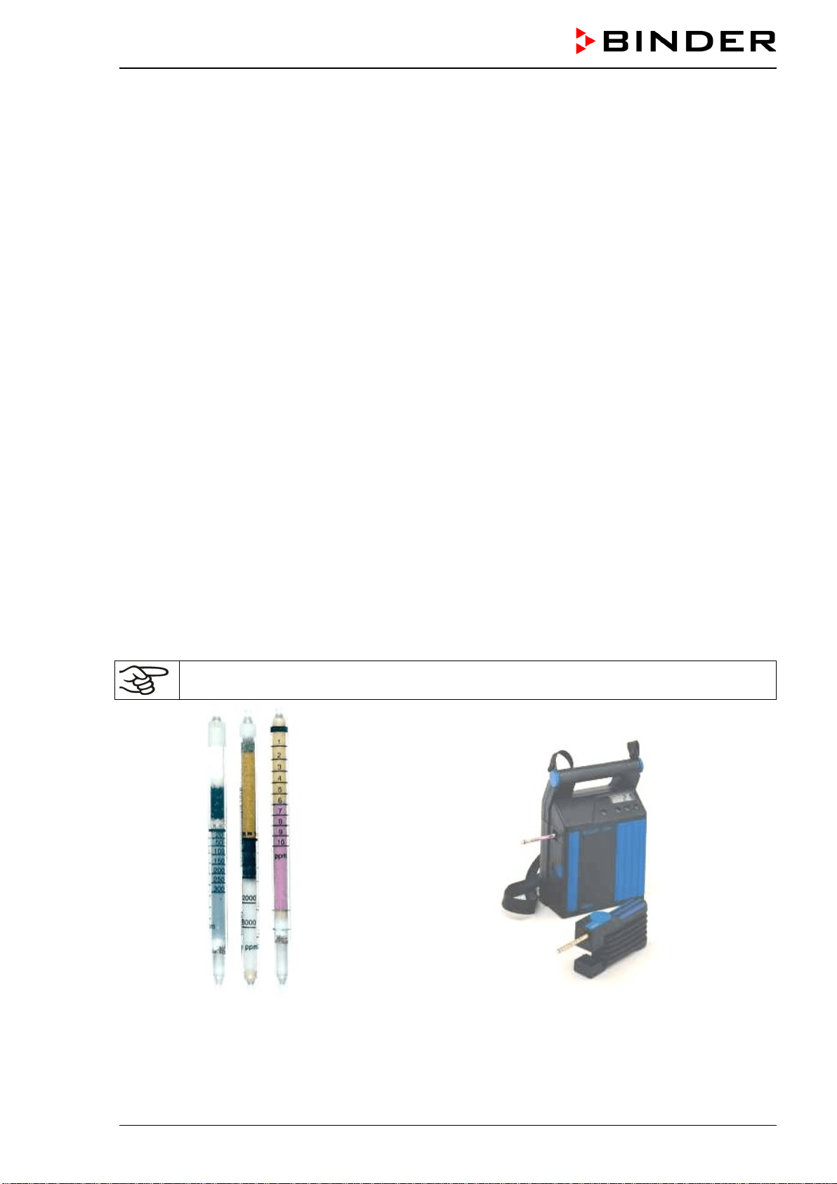
CB-S / CB-S-UL (E7) 06/2020 page 76/119
Example:
If a pH of 7.2 is measured in a medium buffered with 2.20 g NaHC0
3
per liter, there must be 8 vol.-% CO
2
surrounding this medium.
19.1.2 Measuring CO
2
directly via chemical indicator tubes
This is a common do-it-yourself test for many users. A chemical color reaction in a glass tube shows the
CO
2
concentration. A standardized volume of air from inside the incubator has to be suctioned through
this glass tube to get a quantitative test result. Therefore, use a special hand pump with a standardized
suction volume.
Procedure (example):
(1) Break off both ends of the glass tube or remove the plugs.
(2) Pin the end with the higher end of the scale to the adapter of the hand pump that belongs to that
test system.
(3) Pin the other end through the silicone access port of the inner chamber door.
(4) Take one sample volume out of the inner chamber volume by pressing the pump fully together and
releasing it afterwards.
(5) The standardized volume is suctioned through the glass tube and the chemical indicator changes
its color beginning from the side pinned into the chamber in the direction of the hand pump.
(6) The more CO
2
is inside the chamber the more the chemical reaction will cause a color change of
the chemical reactor.
(7) You can read the CO
2
concentration by the scale directly printed on the glass tube or a delivered
reference-reading rule.
(8) The result must then be corrected to the current ambient pressure. The required formula is printed
on the instruction sheet of such systems.
All the necessary equipment must be supplied by one manufacturer only and in a defined test system.
Note: These test systems are not very accurate. A typical accuracy is around 10% of the full-scale value.
These test systems are not suitable for calibrating the BINDER FPI sensor system.
Figure 17: Example of chemical indicator
tubes
Figure 18: Example of a hand pump (foreground) and elec-
trical pump (background)
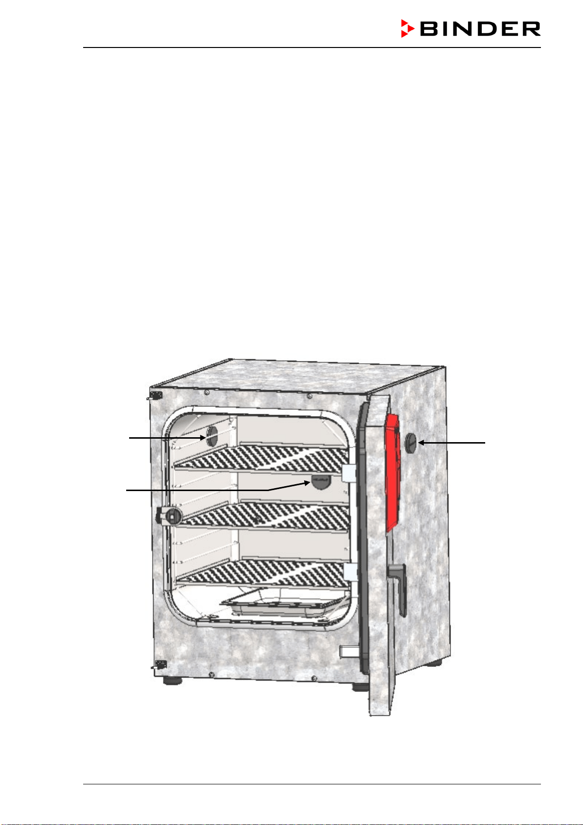
CB-S / CB-S-UL (E7) 06/2020 page 77/119
19.1.3 Measuring CO
2
directly with an electronic infrared measuring device
The easiest way of measuring the CO
2
concentration is by electronic sensor systems. BINDER offers the
portable measuring device model CTM 01 that was specifically designed to measure temperature and
CO
2
concentration inside CO
2
incubators. The CTM 01 is suitable both for reference measurements in
certified laboratories, and for service purposes. Please contact the BINDER INDIVIDUAL team.
19.2 Temperature reference measurement
When performing a temperature reference measurement using an electronic measuring, and temperature
display device, it is important to use a device traceable to an acknowledged standards/calibration institu-
tion (DKD, PTB for Germany) with valid calibration certificate.
Note: The cable of the sensor must be thin enough to lay it over the door gasket of the incubator without
causing any leakages.
20. Options
20.1 Silicone access ports 30 mm / 1.18 in, closable with 2 silicone plugs
(8012-0558 rear, 8012-0559 left, 8012-0560 right) (option)
(a)
(b)
(c)
Figure 19: Positions of the optional silicon access ports left (a), rear (b), and right (c)
CB-S / CB-S-UL (E7) 06/2020 page 78/119
A warning sticker is located above each access port.
When operating a chamber with silicon access ports, both silicon plugs must tightly close the access
ports. If the plugs are inserted in a not-gastight manner, or if plugs are missing, CO
2
gas may escape into
the environment. The CO
2
control only turns off when the chamber door is opened.
DANGER
Danger of suffocation and poisoning by high concentration of CO
2
(> 4 Vol.-%).
Death by suffocation
Tightly close each access port with two plugs during operation.
20.2 Base on castors (option)
In order to obtain easy access to the incubator and to avoid contamination of the incubator caused by soil
pollution, BINDER recommends using the base on castors.
The mounting instructions 7001-0147 delivered with the base on castors describe its in-
stallation (Art. No. 9051-0024).
20.3 Flat stacking frame (option)
We recommend not stacking CO
2
incubators directly on top of one another in order to avoid transmission
of shocks and vibrations from one chamber to the other. This could happen e.g. while opening or closing
the door, cleaning, loading and unloading the chamber. BINDER offers a flat stacking frame for safe
stacking of two incubators.
20.4 APT-COM™ 4 Multi Management Software (option)
The chamber is regularly equipped with an Ethernet interface (15) that can connect the BINDER APT-
COM™ 4 Multi Management Software. The MAC Address is indicated in the “Ethernet” controller menu
(chap. 16.1.1). The actual temperature and CO
2
values are given at adjustable intervals. Programming
can be performed graphically via PC. Up to 100 chambers can be cross-linked. For further information
please refer to the APT-COM™ 4 operating manual.
20.5 Data logger kit (option)
The BINDER Data Logger Kit offers an independent long-term measuring system for temperature. It is
equipped with a keyboard and a large LCD display, alarm functions and a real-time function. Measure-
ment data are recorded in the Data Logger and can be read out after the measurement via the RS232
interface of the Data Logger. It offers a programmable measuring interval and permits storing up to 64000
measuring values. Reading out is done with the Data Logger evaluation software. You can give out a
combined alarm and status protocol directly to a serial printer.
Data Logger Kit T 220: Temperature range -90 °C / -130 °F up to +220 °C / 428 °F
For detailed information on installation and operation of the BINDER Data Logger, please
refer to the mounting instructions Art. No. 7001-0204 and to the original user manual of the
manufacturer, supplied with the data logger.

CB-S / CB-S-UL (E7) 06/2020 page 79/119
20.6 Analog outputs for temperature and CO
2
(option)
With this option, the CO
2
incubator is equipped with analog outputs 4-20 mA for temperature and CO
2
.
These outputs allow transmitting data to external data registration systems or devices.
The connection is realized as a DIN socket at the rear of the CO
2
incubator as follows:
ANALOG OUTPUT 4-20 mA DC
PIN 1: Temperature –
PIN 2: Temperature +'
PIN 3: CO
2
–
PIN 4: CO
2
+
CO
2
range: 0 vol.-% up to 20 vol.-%
Temperature range: 0 °C / 32°F up to +200 °C / 392°F
A suitable DIN plug is enclosed.
Figure 20: Pin allocation of DIN socket for option analog outputs
21. Avoiding microbial contamination
The main types of microbial contaminants in cell and tissue culture are bacteria, fungi, yeast, mycoplas-
ma, and viruses. This chapter gives an overview of potential sources of contamination and precautions
and measures to eliminate them.
21.1 Cells and media
• Primary cultures from the original tissue
• Cells/cell lines from unknown sources or from cell banks: Use only cells of known and tested origin.
Monitoring and routine screening of new cultures.
• Media and sera: Use only sera of known and tested origin (mycoplasma free, e.g., UV or γ radiated).
• Virus suspensions, antibody solutions etc. Use only reagents of known and tested origin.
• Laboratory instruments, media and reagents, which were exposed to possible contaminated cultures
must be sterilized / autoclaved / disposed.
• Antibiotics in the cell culture media may prevent bacteria detection: Use antibiotics selectively and
economically.
21.2 Laboratory conditions / equipment around the CO
2
incubator
Possible sources of contamination in the cell culture lab are airborne germs, lab equipment, building fea-
tures, and the lab personnel.
• Keep pipettes and instruments sterile after autoclaving.
• Bio safety cabinets (laminar air flow) should have a minimum of items apart from aspirator tube and
burner. Items shall be positioned within easy reach and separate from each other. Disinfect surfaces
with an alcohol-based disinfectant before and after use, clean the space underneath the bench, and
carry out regular sterility tests of the filters.
• Regular cleaning / disinfection of laboratory equipment such as a centrifuge, microscope, water bath,
refrigerator, and telephone.
• No equipment should be placed on the floor.
• Rough or humid walls are not suitable.
• Identify leaking doors and windows and make them airtight.

CB-S / CB-S-UL (E7) 06/2020 page 80/119
• Use air conditioning with special filters.
• Reduce the number of personnel and their movements in the lab by careful positioning all relevant
equipment. For practical reasons, install the CO
2
incubator close to the laminar air flow bench.
• Regular microbiological monitoring of the cell culture laboratory.
21.3 Working and behavior in the lab
Sources of contamination are often the laboratory personnel themselves (surface germs, oral flora droplet
transfer) and handling the equipment and cultures. We recommend staff training in aseptic techniques,
laboratory safety and good laboratory practice (GLP).
Examples of general rules to reduce the contamination risks
• Reduce hand germ count (wash hands with antimicrobial soap, dry with paper tissues, and rub dry
hands with alcoholic solution).
• Wear appropriate clothing (work coat, shoes, face mask)
• Keep as few personnel as possible in the cell culture lab.
Examples of sterile working method
• Work "clean-to-dirty", i.e., handle confirmed uncontaminated cells first, unknown or untested cells next,
and lastly, if necessary, cells suspected to be contaminated.
• Perform daily microscopic observations of cultures and specific tests for the bacteria and fungi as part
of a controlled routine. Test cultures for sterility before starting work.
• Keep working surfaces clean. Immediately wipe spilled liquids with alcohol solutions.
• No mouth contact on pipettes.
• Never work on top of open sterile containers.
21.4 Chamber design and equipment
The design concepts behind the CO
2
incubator considerably reduce the risk of contamination. Among
them are:
Even surfaces for easy manual cleaning
• The inner surfaces are smooth and therefore easy to clean. The inner chamber is deep-drawn from a
single piece of steel, polished (suitable for pharmaceutical work) and has no welds or inaccessible
corners. The hinges and the seal of the inner glass door are glued from the outside, which also aids
cleaning of the inner chamber.
Removable parts for cleaning and autoclaving
• The shelves are easily removed without screws. In this way, you can clean them hygienically in every
laboratory dishwasher before hot-air sterilization. It is possible to autoclave the shelves. But this is
generally not necessary because they can remain inside the incubator during sterilization.
Door gasket
• The inner door gasket is removable and autoclavable.
Gas fine filter
• The incoming gas used in the operation passes through a fine filter (aseptic filter, filtration efficiency
99.99%, particle size 0.45 µm) with a high filtration efficiency, which can also filter the smallest parti-
cles (chap. 24.4).

CB-S / CB-S-UL (E7) 06/2020 page 81/119
CO
2
measuring system in the inner chamber
• You can remove the CO
2
sensor from the inner chamber by hand for disinfection (chap. 22.3).
Condensation prevention
• Condensation in the inner chamber represents a particular risk of contamination. The humidifying sys-
tem with water pan with integrated condensation point developed by BINDER is an effective and easy
way to ensure high humidity (95 +/- 2% r.h.) inside the incubator without any condensation forming on
the inner surfaces.
Hot air sterilization
• The heating system of the chamber permits hot-air auto-sterilization (chap. 23). Thus, a temperature of
180 °C / 356°F is maintained for a 30-minute period on all internal surfaces during its cycle, resulting
in sterilization of the entire inner chamber. Therefore, this procedure meets all international guidelines
regarding hot air sterilization, e.g. AAMI ST63, DIN 58947, European Pharmacopoeia.
21.5 Handling the CO
2
incubator
Any manipulation of the CO
2
incubator involves some contamination risks, from installation to opening of
the doors and regular cleaning.
Installation away from sources of contamination
• Do not place the CO
2
incubator on the floor or close to windows and doors. Use the optional stand, if
appropriate.
Reduce the periods in which the door is open.
• Do not open the door too frequently.
• Placing items in order inside the incubator results in shorter door opening times.
Water pan
• Fill the water pan with distilled, sterilized water (chap. 4.3). Never use ion exchange water; ion ex-
changers are propagation sites for bacteria.
• Clean and refill the pans 2 to 3 times a week. For evacuation, remove the water pan. It is autoclava-
ble.
• If desired, you can add microbiologically inhibiting substances such as copper chips, copper sulphate
or ethylene diamine tetra-vinegar acid (EDTA) in a concentration of 1 to 5 mmol/l.
Avoiding condensation caused by ambient conditions
• Ambient room conditions have an effect on condensation inside the incubator, which can be caused by
insufficient wall clearances, preventing even dissipation of heat, air movement or direct sunlight. If the
temperature distribution inside the chamber becomes uneven, condensation may form on the cooler
surfaces.
• Maintain distances from the wall: rear 100 mm / 3.94 in, sides 50 mm / 1.97 in.
• Do not place the chamber in front of a window. No direct sunlight. No air movement.
• Permissible ambient temperature range for operation: +18 °C / 64.4°F to +30 °C / 86°F. Ideal ambient
temperature: at least 7 degrees below the intended working temperature. E.g., working temperature
37 °C / 98.6°F = ambient temperature 30 °C / 86°F and less.
• The incubator should be precisely calibrated / adjusted.
Regular cleaning, decontamination, and sterilization
• Clean the shelves, glass door, gaskets, and inner chamber weekly (for cleaning see chap. 22.1, for
decontamination see chap. 22.2). You can clean the shelves in a laboratory dishwasher and, if need-
ed, individually autoclave them.
• Regularly use the hot air sterilization function (chap. 23) following cleaning. The shelves and the emp-
tied water pan can remain inside the incubator during this operation.
CB-S / CB-S-UL (E7) 06/2020 page 82/119
• Replace the CO
2
sterile filter (once or twice a year depending on usage).
What to do in case of contamination?
• Throw away / autoclave contaminated cultures.
• Carefully inspect cultures that seem to be uncontaminated.
• Clean the incubator as described. Wipe the inner chamber and the doors with a disinfectant and allow
to dry. Autoclave the shelves. Empty the water pan and autoclave it.
• Perform hot air sterilization.
22. Cleaning, decontamination / disinfection, and sterilization
Clean the chamber after each use in order to prevent potential corrosion damage by ingredients of the
charging material.
Prior to renewed startup, allow the chamber to completely dry after all cleaning and decontamination
measures.
DANGER
Electrical hazard by water entering the chamber.
Deadly electric shock.
∅ Do NOT spill water or cleaning agents over the inner and outer chamber surfaces.
∅ Do NOT put ANY cleaning aids (cloth or brush) into slots or openings on the chamber.
∅ Before cleaning, turn off the chamber at the main power switch (2) and disconnect the
power plug. Let the chamber cool down to ambient temperature.
∅ Completely dry the chamber before turning it on again.
DANGER
Danger of explosion due to cleaning agents on hot surfaces.
Serious injury or death from burns and / or explosion pressure.
∅ Before cleaning, turn off the chamber at the main power switch and disconnect the
power plug.
∅ Before cleaning, let the chamber cool down to ambient temperature.
∅ Completely dry the chamber before turning it on again.
CB-S / CB-S-UL (E7) 06/2020 page 83/119
22.1 Cleaning
Disconnect the CO
2
incubator from the power supply before cleaning. Disconnect the power plug.
The interior of the chamber must be kept clean. Thoroughly remove any residues of the charg-
ing material.
Wipe the surfaces with a moistened towel. In addition, you can use the following cleaning agents:
Exterior surfaces,
instrument panel:
Standard commercial cleaning detergents free from acid or halides.
Alcohol-based solutions.
We recommend using the neutral cleaning agent Art. No. 1002-0016.
Inner chamber,
shelves,
water pan:
Standard commercial cleaning detergents free from acid or halides.
Copper sulphate solutions or alcohol-based solutions.
We recommend using the neutral cleaning agent Art. No. 1002-0016.
CO
2
sensor
Alcohol-based solutions
Do not immerse the CO
2
sensor into the solution.
Disinfection with alcohol or an alcohol-based surface disinfectant without corro-
sive effect, free from acid or halides. We recommend using the disinfectant spray
Art. No. 1002-0022.
Silicone door gasket: Alcohol-based solutions or neutral cleaning agent Art. No. 1002-0016.
Zinc coated hinge
parts, rear chamber
wall
Standard commercial cleaning detergents free from acid or halides. Do NOT use
a neutral cleaning agent on zinc coated surfaces.
Do not use cleaning agents that may cause a hazard due to reaction with components of the device or
the charging material. If there is doubt regarding the suitability of cleaning products, please contact
BINDER service.
We recommend using the neutral cleaning agent Art. No. 1002-0016 for a thorough cleaning.
Any corrosive damage that may arise following use of other cleaning agents is excluded from
liability by BINDER GmbH.
Use only the products recommended by BINDER for cleaning and disinfection
NOTICE
Danger of corrosion by using unsuitable cleaners.
Damage to the chamber.
∅ Do NOT use acidic or chlorine cleaning detergents.
∅ Do NOT use a neutral cleaning agent on other kind of surfaces e.g., the zinc coated
hinge parts or the rear chamber wall.
For surface protection, perform cleaning as quickly as possible.
After cleaning completely, remove any cleaning agents from the surfaces with a moistened
towel. Let the chamber dry.
Soapsuds may contain chlorides and must therefore NOT be used for cleaning.
With every cleaning method, always use adequate personal safety controls.
CB-S / CB-S-UL (E7) 06/2020 page 84/119
Following cleaning, leave the chamber door open or remove the access port plugs.
The neutral cleaning agent may cause health problems in contact with skin and if ingested.
Follow the operating instructions and safety hints labeled on the bottle of the neutral clean-
ing agent.
Recommended precautions: To protect the eyes use sealed protective goggles. Wear gloves. Suitable
protective gloves with full contact: butyl or nitrile rubber, penetration time >480 minutes.
CAUTION
Danger of chemical burns through contact with skin or ingestion of the
neutral cleaning agent.
Skin and eye damage. Environmental damage.
∅ Do not ingest the neutral cleaning agent. Keep it away from food and bev-
erages.
∅ Do NOT empty the neutral cleaning agent into drains.
Wear protective gloves and goggles.
Avoid skin contact with the neutral cleaning agent.
Following use of the neutral cleaning agent and prior to hot-air sterilization, remove any agent
residues by using a moistened towel in order to avoid formation of permanent residues.
22.2 Decontamination / chemical disinfection of the chamber
The operator must ensure that proper decontamination is performed in case a contamination of the
chamber by hazardous substances has occurred.
Disconnect the CO
2
incubator from the power supply prior to chemical decontamination / disinfection. Pull
the power plug.
Do not use decontamination agents that may cause a hazard due to reaction with components of the
device or the charging material. If there is doubt regarding the suitability of cleaning products, please
contact BINDER service.
You can use the following disinfectants:
Inner chamber
Standard commercial surface disinfectants free from acid or halides.
Alcohol-based solutions.
We recommend using the disinfectant spray Art. No. 1002-0022.
For chemical disinfection, we recommend the disinfectant spray Art. No. 1002-0022.
Any corrosive damage that may arise following use of other disinfectants is excluded from
liability by BINDER GmbH.
With every decontamination / disinfection method, always use adequate personal safety con-
trols.
CB-S / CB-S-UL (E7) 06/2020 page 85/119
In case of contamination of the interior by biologically or chemically hazardous material, there are two
possible procedures depending on the type of contamination and charging material.
1. Spray the inner chamber with an appropriate disinfectant.
Before start-up, the chamber must be absolutely dry and ventilated, as explosive gases may form dur-
ing the decontamination process.
2. You can sterilize the shelves in a sterilizer or autoclave.
In case of eye contact, the disinfectant spray may cause eye damage due to chemical
burns. Follow the operating instructions and safety hints labeled on the bottle of the disin-
fectant spray.
Recommended precautions: To protect the eyes use sealed protective goggles.
CAUTION
Danger of chemical burns through eye contact with the disinfectant
spray.
Eye damage. Environmental damage.
∅ Do NOT empty the disinfectant spray into drains.
Wear protective goggles.
Following frequent use of the disinfectant spray and prior to hot-air sterilization, remove any
agent remainder by using the neutral cleaning agent and then a moistened towel to avoid for-
mation of permanent residues.
After using the disinfectant spray, allow the incubator to dry thoroughly, and aerate it suffi-
ciently.
22.3 Disinfection of the CO
2
sensor
To ensure complete disinfection and proper function of the sensor, BINDER recommends a wipe disinfec-
tion of the sensor head with pure alcohol or non-corrosive alcohol-based surface disinfectants. The disin-
fectant must be non-corrosive and free of chlorine or any acid. We recommend using the disinfectant Art.
No. 1002-0022. Avoid strong shocks when handling the CO
2
sensor.
NOTICE
Danger of damage to the CO
2
sensor through improper handling (excess tempera-
ture, immersion into liquids, shocks).
Damage to the CO
2
sensor.
∅ Do NOT immerse the CO
2
sensor into liquids.
∅ Do NOT expose the CO
2
sensor to autoclaving.
∅ Do NOT expose the CO
2
sensor to hot-air sterilization.
Avoid strong shocks of the CO
2
sensor (by putting it down hard, or dropping).
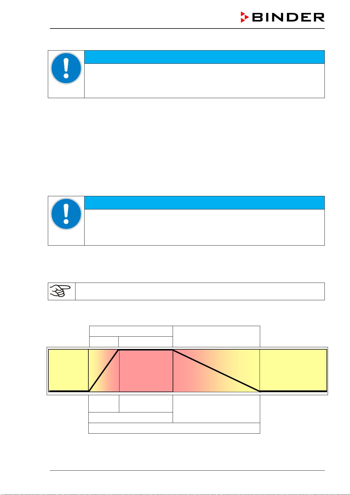
CB-S / CB-S-UL (E7) 06/2020 page 86/119
We recommend regular disinfection of the CO
2
sensor.
NOTICE
Danger of damage to the CO
2
sensor when connecting or removing it during opera-
tion.
Damage to the CO
2
sensor.
Connect or remove the CO
2
sensor only with the chamber turned off.
Recommended procedure:
• Turn off the chamber
• Pull out the sensor
• Spray the sensor head with alcohol or wipe it clean with a soaked cloth. Observe the reaction time of
the disinfectant used.
• Before reinserting the CO
2
sensor, it must be completely dry.
• The filter in the front of the sensor only needs replacing when damaged or dirty.
The CO
2
sensor head was especially adjusted for the specific chamber. To avoid confusion, an adhesive
label with a serial number is adhered to the sensor head. When exchanging the sensor, repeat CO
2
ad-
justment.
NOTICE
Danger of confusing CO
2
sensors.
Invalid calibration.
Do NOT change the CO
2
sensor head.
Note down the serial number of the CO
2
sensor.
23. Hot-air sterilization at 180 °C / 356 °F
The very first sterilization after operation may cause an odor. This is not a quality defect. We
recommend ventilating well the room during sterilization.
23.1 Overview
Effective sterilization
Cooling down
Heating up
Holding
approx. 2
hours
4 hours
approx. 6 hours
6 hours
Sterilization cycle: Total duration approx. 12 hours
Figure 21: Temperature set-point profile and phases of the sterilization cycle
37 °C
190 °C
CB-S / CB-S-UL (E7) 06/2020 page 87/119
The chamber can perform an automatically controlled hot-air sterilization cycle. This procedure will take
approx. 12 hours and consists of the following steps:
• Heating up phase: The incubator heats up the inner chamber as fast as possible to the sterilization
set-point temperature
• Holding phase: Constant sterilization set-point temperature
The sterilization set-point temperature is pre-set in factory to 190 °C / 374 °F. When this temperature
is reached, the holding phase begins. The duration of the holding phase is in total 4 hours. This en-
sures that 180 °C / 356 °F is maintained on all internal surfaces for at least 30 minutes.
The effective sterilization phase consists of the heating up and holding phase with a total duration of 6
hours. The necessary duration for the proper sterilization is then completed. A cooling-down phase fol-
lows.
• Cooling down phase: Cooling down to 37 °C / 98.6°F. It starts 6 hours after begin of the sterilization
cycle.
As soon as the cooling down phase starts, the information message “Sterilization success” indicates
the successful sterilization.
The precise duration of the entire sterilization cycle depends on the ambient temperature at the installa-
tion site and can thus vary. At an ambient temperature of 25 °C / 77 °F, the total duration is approx. 12
hours. You can shorten the cooling-down time by prematurely terminating the sterilization cycle (chap.
23.4) during the cooling-down phase, i.e. no sooner than after 6 hours.
During sterilization, the CO
2
valve is closed and the CO
2
controller turns off entirely.
23.2 Performing a hot-air sterilization
23.2.1 Preparations for hot-air sterilization
Before carrying out the first hot-air sterilization, remove any protective lamination sheet from
the inner metal surfaces.
• Turn off the chamber
• Pull out the CO
2
sensor without any rotation from the connection socket in the upper part of the rear
and remove it from the inner chamber.
The CO
2
sensor is temperature resistant up to a maximum temperature of 60 °C / 140 °F. It is
therefore required to remove it before performing a hot-air sterilization.
NOTICE
Danger of damage to the CO
2
sensor due to excess temperature.
Damage to the CO
2
sensor.
∅ Do NOT expose the CO
2
sensor to hot-air sterilization.
The CO
2
sensor head was especially adjusted for your specific chamber. To avoid confusion, an ad-
hesive label with a serial number is adhered to the sensor head. When exchanging the sensor, repeat
CO
2
control adjustment.
NOTICE
Danger of confusing CO
2
sensors.
Invalid calibration.
Do NOT change the CO
2
sensor head.
Note down the serial number of the CO
2
sensor.
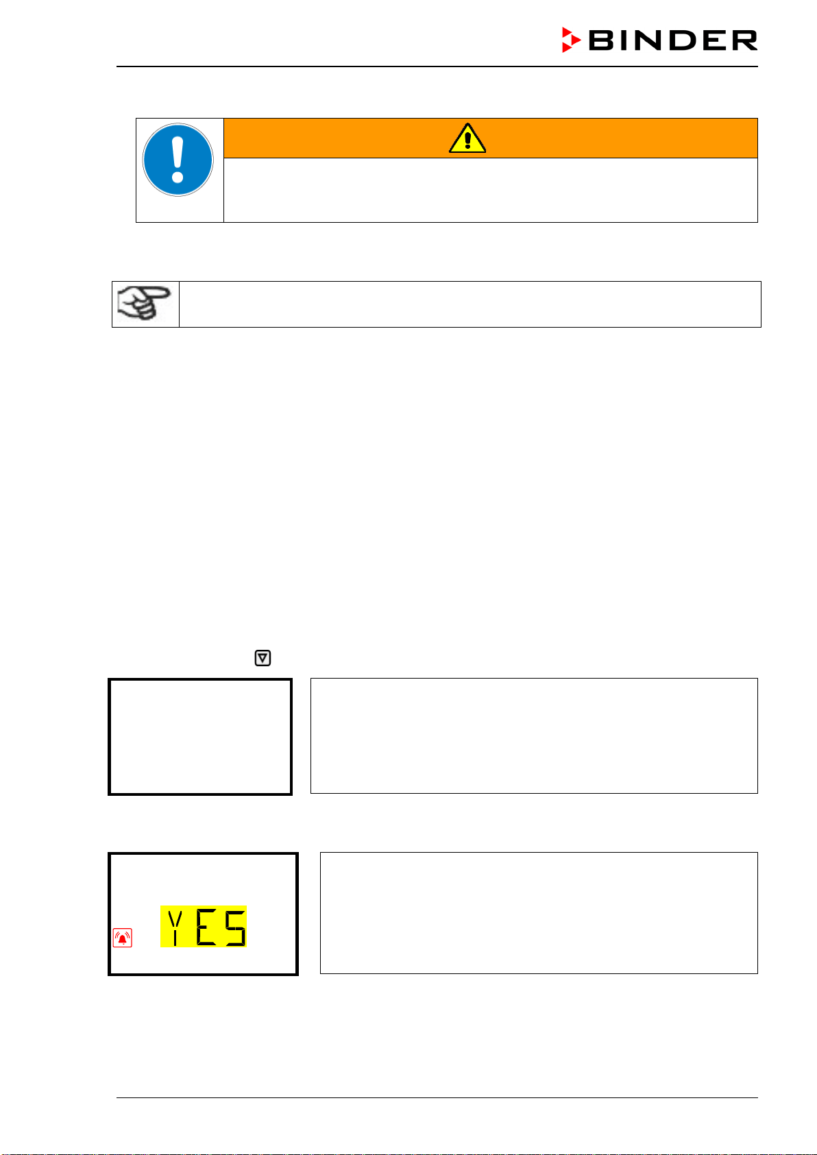
CB-S / CB-S-UL (E7) 06/2020 page 88/119
• Empty the water pan.
WARNING
Danger of implosion caused by a filled water pan during sterilization.
Damage to the chamber.
Empty the water pan before starting the hot-air sterilization.
• Clean the chamber.
• Water pan and shelves must be inside the incubator, the water pan at its usual place on the bottom.
Before starting a hot-air sterilization, the entire interior must be clean and dry. No residue of
e.g., water, medium or plastic must remain inside the chamber.
• Close the inner glass door and the outer chamber door.
• Turn on the chamber.
• Activate the sterilization procedure (chap. 23.3.1).
23.3 Starting and running the hot-air sterilization cycle
Make sure that before starting the hot-air sterilization the following is done:
• The water pan was emptied
• All samples were removed from the chamber
• The CO
2
sensor is disconnected
23.3.1 Starting sterilization
Required access level: “User”.
Path: Normal display Sterilization
“Sterilization” menu.
In this menu you can start a sterilization or stop a running sterilization.
Sterilization
With the Back button you can go back to Normal display.
Press the OK button to enter the sterilization submenu.
“Start sterilization” submenu
The current setting flashes. Select with the arrow buttons between
YES (start sterilization) and NO (do not start sterilization).
To start the sterilization cycle select “YES” and press the OK button
to confirm.
Start sterilization
After selecting “NO”: The controller changes back to the “Sterilization” menu.
After selecting “YES”: Sterilization starts and the controller changes to Normal display.
No sterilization can be started if the CO
2
sensor is still plugged-in. The information message ““CO2 sen-
sor plugged-in” appears and the controller returns to Normal display.
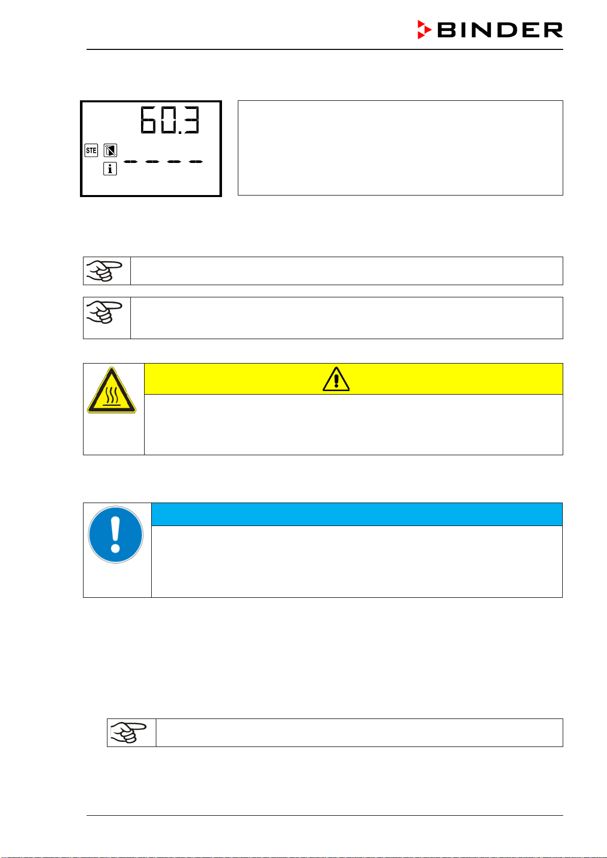
CB-S / CB-S-UL (E7) 06/2020 page 89/119
23.3.2 Performance during sterilization
Normal display during sterilization (example during heating up phase)
Sterilization
The information message “Sterilization” is shown alternating with the indication “Temp. / CO2”.
The CO
2
actual value display shows “ – – – – ” because the CO
2
sensor is disconnected.
The zero-voltage relay alarm output and the buzzer are not activated.
When starting a hot-air sterilization, CO
2
control deactivates automatically.
The safety controller settings are inactive during sterilization. They become functional again
following termination of the sterilization and/or restarting the chamber at the main power
switch.
Glass door and inner chamber become hot during sterilization.
CAUTION
Danger of burning by touching hot chamber parts during a sterilization.
Burns.
∅ Do NOT touch the glass door, glass door, inner surfaces, and door gaskets during a
sterilization.
Opening the outer door leads to prematurely terminating the running sterilization cycle (chap. 23.5). If this
happens during the heating up or holding phase (during 6 hours after starting the sterilization cycle), steri-
lization will be ineffective (chap. 23.4.1).
NOTICE
Danger of interrupting the temperature reaction time by opening the outer door
during the heating up or holding phase.
Ineffective sterilization.
∅ Do NOT open the chamber doors during the heating up or holding phase of the sterili-
zation cycle
23.3.3 Completing the entire sterilization cycle
After 6 hours the information message “Sterilization success” indicates the successful sterilization. The
cooling down phase starts.
The entire sterilization cycle ends after a total of approx. 12 hours.
• When the inner chamber has cooled down to a value below 60 °C / 140 °F, turn off the chamber and
plug in the CO
2
sensor.
The CO
2
sensor is temperature resistant up to a maximum temperature of 60 °C / 140 °F
• Start up the chamber (chap. 6)
The chamber is now ready to operate.
CB-S / CB-S-UL (E7) 06/2020 page 90/119
23.4 Prematurely terminating the sterilization cycle – effects
Prematurely terminating the sterilization cycle means terminating it before the entire 12-hour duration is
completed. Whether effective sterilization has occurred depends on the time that has elapsed before.
• Premature termination after less than 6 hours: Prevents effective sterilization.
This is indicated by the alarm message “Sterilization failed”.
• Premature termination after more than 6 hours: The chamber is definitely in the cooling-down phase,
meaning that the necessary duration for the proper sterilization phase has occurred.
This is indicated by the information message “Sterilization success”.
23.4.1 Premature termination after less than 6 hours: Ineffective sterilization
When prematurely terminating the sterilization cycle, it may be that the cells/pathogens inside the cham-
ber have not all been killed. If necessary, you should repeat the sterilization.
NOTICE
Danger of interrupting the temperature reaction time by prematurely terminating
the sterilization.
Ineffective sterilization.
If necessary, repeat the sterilization.
The glass door and inner chamber become hot during sterilization.
CAUTION
Danger of burning by touching hot chamber parts during or after a sterilization.
Burns.
∅ Do NOT touch the glass door and inner surfaces for approx. 7 hours after prematurely
terminating the sterilization cycle.
• When the inner chamber has cooled down to a value below 60 °C / 140 °F, turn off the chamber and
plug in the CO
2
sensor.
The CO
2
sensor is temperature resistant up to a maximum temperature of 60 °C / 140 °F
• Start up the chamber (chap. 6).
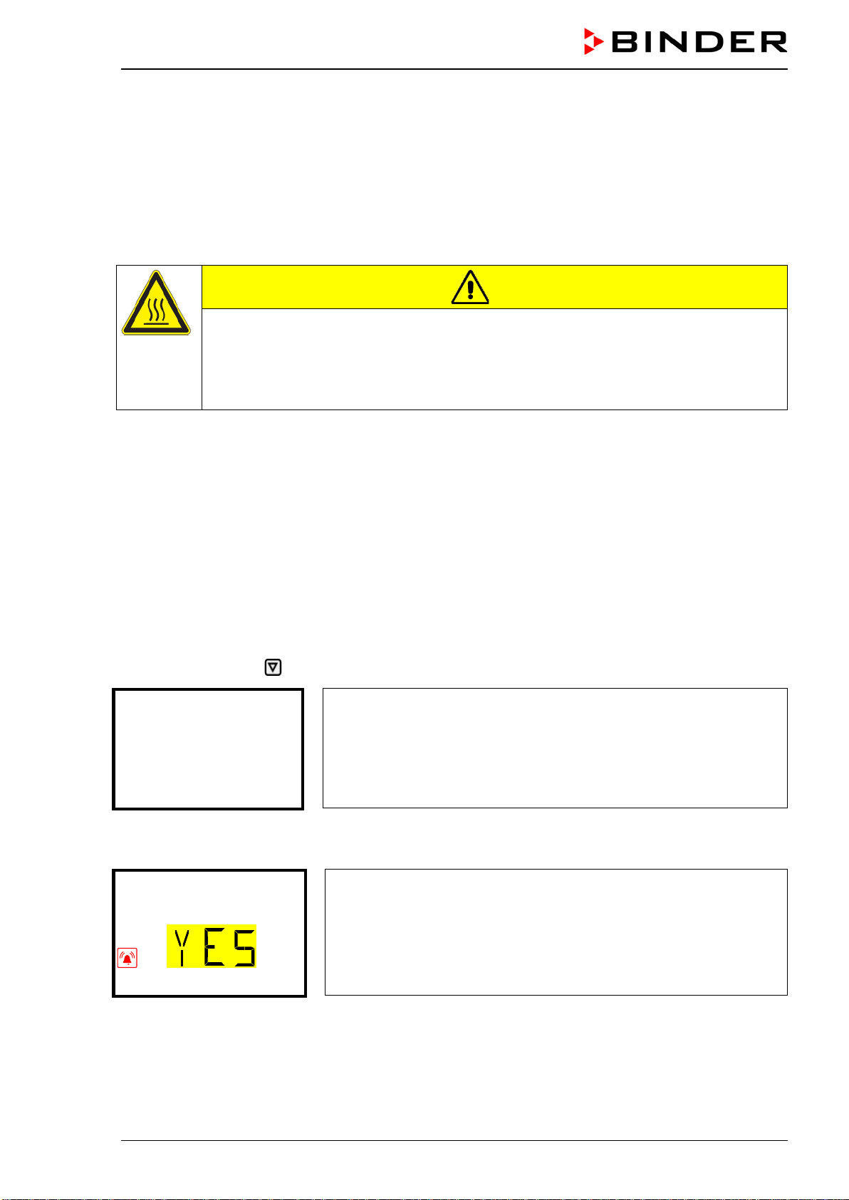
CB-S / CB-S-UL (E7) 06/2020 page 91/119
23.4.2 Premature termination after more than 6 hours, i.e., during the cooling-down
phase: successful sterilization
The duration of the entire sterilization is approx. 12 hours. If you want to shorten the sterilization proce-
dure in order to save time, you can prematurely terminate it during the cooling-down phase, i.e. no sooner
than after 6 hours. At this point, the inner temperature is still approx. 140 °C / 284 °F.
The effective sterilization phase (heating up and holding phase) is automatically finished after 6 hours
The chamber is in the cooling-down phase, meaning that the necessary duration for the proper steriliza-
tion has occurred. Glass door and inner chamber become hot during sterilization.
CAUTION
Danger of burning through touching the glass door and inner chamber during or
after a sterilization.
Burns.
∅ Do NOT touch the glass door and inner surfaces for approx. 4 hours after prematurely
terminating the sterilization cycle.
23.5 Prematurely terminating the sterilization cycle – procedure
Three events lead to terminating the sterilization cycle prematurely:
• Cancelling sterilization via the controller menu (chap. 23.5.1)
• Opening the outer door (chap. 23.5.2)
• Turning off the chamber at the main power switch (chap. 23.5.3) or a power failure
23.5.1 Cancelling sterilization via the controller menu
Required access level: “User”.
Path: Normal display Sterilization
“Sterilization” menu.
In this menu you can start a sterilization or stop a running sterilization.
Sterilization
With the Back button you can go back to Normal display.
Press the OK button to enter the sterilization submenu.
“Stop sterilization” submenu.
The current setting flashes. Select with the arrow buttons between
YES (stop sterilization) and NO (do not stop sterilization).
To stop the sterilization select “YES” and press the OK button to con-
firm.
Stop sterilization
After selecting “NO”: The controller changes back to the “Sterilization” menu.
After selecting “YES”: The controller changes to Normal display. The sterilization is terminated. If termina-
tion occurred after less than 6 hours, the alarm message “Sterilization failed” is indicated until pressing
the OK button.
CB-S / CB-S-UL (E7) 06/2020 page 92/119
• Do not open the chamber doors until the interior temperature has dropped to 37 °C / 98.6 °F.
• After premature termination the chamber reverts to its standard operational status.
• The CO
2
actual value display shows “ – – – – ” because the CO
2
sensor is disconnected.
As long as the interior temperature remains above the temperature set to trigger the temperature
alarm, the chamber will trigger alarm signals. You can ignore this alarm and turn off the buzzer of the
safety controller by pressing the OK button.
• If necessary, repeat the sterilization.
• When the inner chamber has cooled down to a value below 60 °C / 140 °F, turn off the chamber and
plug in the CO
2
sensor.
The CO
2
sensor is temperature resistant up to a maximum temperature of 60 °C / 140 °F
• Start up the chamber (chap. 6).
23.5.2 Opening the outer door
For safety reasons, the sterilization cycle is automatically aborted if you open the outer chamber door.
• Do not open the glass door and close the outer door immediately.
• After premature termination caused by opening the outer door the chamber reverts to its standard
operational status.
• The CO
2
actual value display shows “ – – – – ” because the CO
2
sensor is disconnected.
As long as the interior temperature remains above the temperature set to trigger the temperature
alarm, the chamber will trigger alarm signals. You can ignore this alarm and turn off the buzzer of the
safety controller by pressing the OK button.
• If necessary, repeat the sterilization.
• When the inner chamber has cooled down to a value below 60 °C / 140 °F, turn off the chamber and
plug in the CO
2
sensor.
The CO
2
sensor is temperature resistant up to a maximum temperature of 60 °C / 140 °F
• Start up the chamber (chap. 6).
23.5.3 Turning off the chamber
For safety reasons, the sterilization cycle is aborted if the chamber is turned off or if there is a power fail-
ure.
Normally you should not terminate sterilization in this way.
• Do not open the chamber doors until the interior temperature has dropped to 37 °C / 98.6 °F.
• After turning on again the chamber at the main power switch, it will revert to its standard operational
status.
• The CO
2
actual value display shows “ – – – – ” because the CO
2
sensor is disconnected.
As long as the interior temperature remains above the temperature set to trigger the temperature
alarm, the chamber will trigger alarm signals. You can ignore this alarm and turn off the buzzer of the
safety controller by pressing the OK button.
• If necessary, repeat the sterilization.
• When the inner chamber has cooled down to a value below 60 °C / 140 °F, turn off the chamber and
plug in the CO
2
sensor.

CB-S / CB-S-UL (E7) 06/2020 page 93/119
The CO
2
sensor is temperature resistant up to a maximum temperature of 60 °C / 140 °F
• Start up the chamber (chap. 6).
24. Maintenance, and service, troubleshooting, repair, testing
24.1 General information, personnel qualification
• Maintenance
See chap. 24.2.
• Simple troubleshooting
Chap. 24.5 describes troubleshooting by operating personnel. It does not require technical intervention
into the chamber, nor disassembly of chamber parts.
For personnel requirements please refer to chap. 1.1.
• Detailed troubleshooting
If errors cannot be identified with simple troubleshooting, further troubleshooting must be performed by
BINDER Service or by BINDER qualified service partners or technicians, in accordance with the de-
scription in the Service Manual.
For personnel requirements please refer to the Service Manual.
• Repair
Repair of the chamber can be performed by BINDER Service or by BINDER qualified service partners
or technicians, in accordance with the description in the Service Manual.
After maintenance, the chamber must be tested prior to resuming operation.
• Electrical testing
To prevent the risk of electrical shock from the electrical equipment of the chamber, an annual repeat
inspection as well as a test prior to initial startup and prior to resuming operation after maintenance or
repair, are required. This test must meet the requirements of the competent public authorities. We rec-
ommend testing under DIN VDE 0701-0702:2008 in accordance with the details in the Service Manu-
al.
For personnel requirements please refer to the Service Manual.
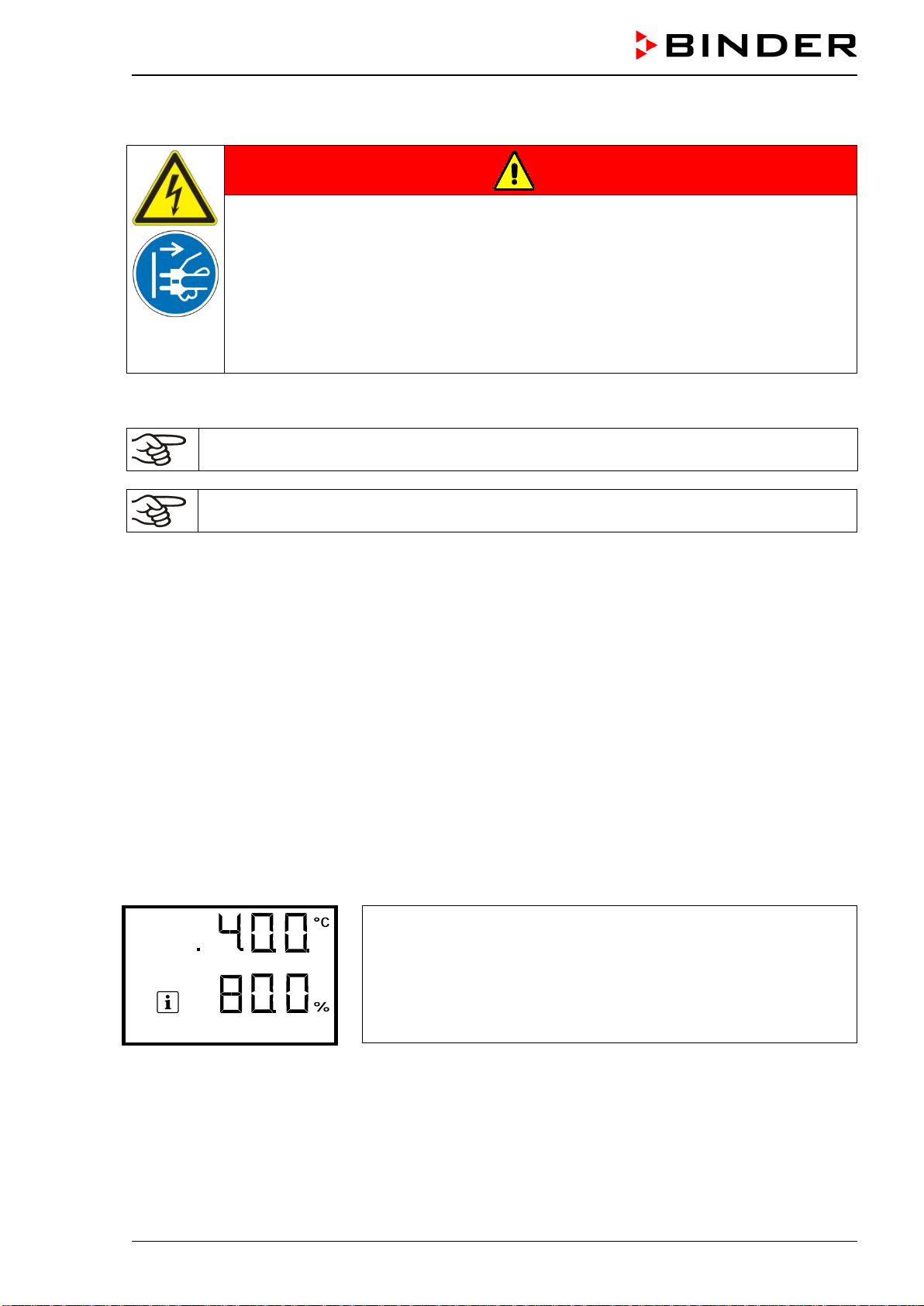
CB-S / CB-S-UL (E7) 06/2020 page 94/119
24.2 Maintenance intervals, service
DANGER
Electrical hazard during live maintenance work.
Deadly electric shock.
∅ The chamber must NOT become wet during operation or maintenance works.
∅ Do NOT remove the rear panel of the chamber.
Before conducting maintenance work, turn off the chamber at the main power switch
(2) and disconnect the power plug.
Make sure that any maintenance work will be conducted by licensed electricians or
experts authorized by BINDER.
Ensure regular maintenance work is performed at least once a year and that the legal requirements are
met regarding the qualifications of service personnel, scope of testing and documentation.
The warranty becomes void if maintenance work is conducted by non-authorized personnel.
Replace the door gasket only when cold. Otherwise, the door gasket may become damaged.
The CO
2
sensor was especially adjusted for the specific chamber. When exchanging the sensor, you
must repeat the CO
2
adjustment.
We recommend taking out a maintenance agreement. Please consult BINDER Service.
BINDER telephone hotline: +49 (0) 7462 2005 555
BINDER fax hotline: +49 (0) 7462 2005 93555
BINDER e-mail hotline: service@binder-world.com
BINDER service hotline USA: +1 866 885 9794 or +1 631 224 4340 x3 (toll-free in the USA)
BINDER service hotline Asia Pacific: +852 390 705 04 or +852 390 705 03
BINDER service hotline Russia and CIS +7 495 988 15 16
BINDER Internet website http://www.binder-world.com
BINDER address BINDER GmbH, post office box 102, D-78502 Tuttlingen
International customers, please contact your local BINDER distributor.
24.3 Service Reminder
You can display the time until the service due in the controller. Keep the OK button pressed down for 5
seconds.
The remaining time in days until maintenance is due is shown in the
text field of the controller display.
Press the OK button to confirm the message.
Service in 364.9 days
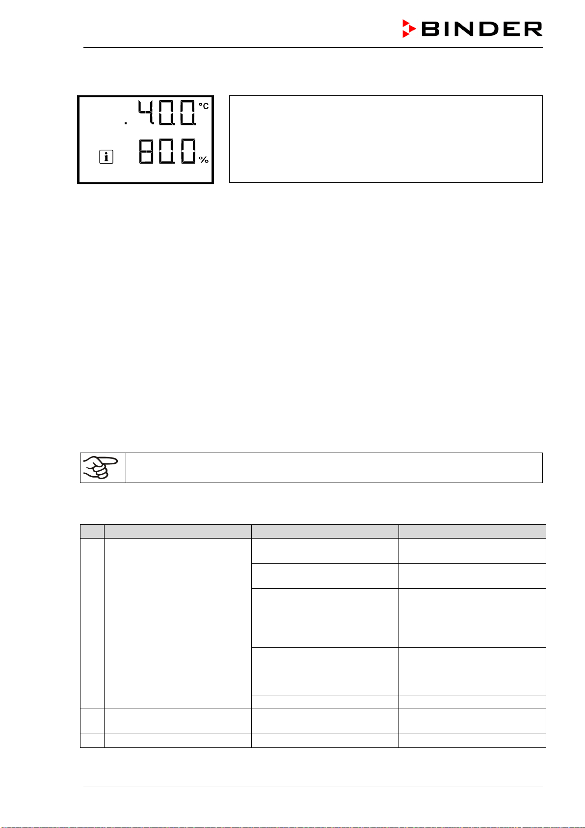
CB-S / CB-S-UL (E7) 06/2020 page 95/119
After the recommended maintenance interval (one year of operation) a message appears on the control-
ler.
The information message “Service due!” is shown in the text field of
the controller display.
Press the OK button to confirm the message.
Service due!
After one week of operation, the message reappears.
24.4 Gas inlet fine filter
When the chamber is operating, the incoming gas passes through a fine gas filter (aseptic filter, filtration
efficiency 99.99%, particle size 0.45 µm). The gas fine filter prevents dirt accumulating in the gas inlet
valves and the tubes leading into the inner chamber, which could be in the gas cylinder or in the supply
tubes.
Service personnel authorized by BINDER will check this filter for pollution at each maintenance interval
and replace it, if appropriate, but at least once a year.
24.5 Simple troubleshooting
Defects and shortcomings can compromise the operational safety of the chamber and can lead to risks
and damage to equipment and persons. If there are is a technical fault or shortcoming, take the chamber
out of operation and inform BINDER Service. If you are not sure whether there is a technical fault, pro-
ceed according to the following list. If you cannot clearly identify an error or there is a technical fault,
please contact BINDER Service.
Only qualified service personnel authorized by BINDER must perform repair.
Repaired chambers must comply with the BINDER quality standards.
24.5.1 General
No.
Fault description
Possible cause
Required measures
1 Chamber without function.
No power supply.
Check connection to power
supply.
Wrong voltage.
Check power supply for voltage
of 120 V / 230 V.
Nominal temperature exceeded
by 10 °C due to chamber fail-
ure. Over temperature protec-
tive device (class 1) responds
(chap. 11.1).
Contact BINDER service.
The miniature fuse for overcur-
rent protection has triggered
(chap. 26.2).
Check chamber fuse and re-
place it if appropriate. If it re-
sponds again, contact BINDER
service.
Controller defective.
Contact BINDER service.
2
Set-point values are not equili-
brated. Icon “1” is displayed.
Operating mode “Idle mode”
activated.
Deactivate operating mode “Idle
mode” (chap. 9.1)
3
Alarm message “Door open”.
The outer chamber door is open
Close chamber door.
CB-S / CB-S-UL (E7) 06/2020 page 96/119
24.5.2 Temperature
No.
Fault description
Possible cause
Required measures
1 Chamber does not heat up.
Pt 100 sensor defective.
Contact BINDER service.
Heating element defective.
Semiconductor relay defective.
2
Chamber is heating permanent-
ly. Set-point is not respected.
Semiconductor relay defective. Contact BINDER service.
3 Temperature inside too low.
Doors not closed.
Close door properly.
Door gaskets defective.
Replace door gaskets.
Controller defective.
Contact BINDER service.
Pt 100 sensor defective.
Controller not adjusted.
Calibrate and adjust controller.
4
Temperature inside too low.
Alarm message
“Temperature range”
Current actual temperature
value outside the tolerance
range.
For causes and actions, see
no. 3.
Operation temporarily possible.
Check the tolerance range set-
tings. With other error messag-
es remove the respective
cause.
5 Temperature inside too high.
Installation site too warm.
Select cooler place of installa-
tion (chap. 3.4).
Difference between the set
temperature and the ambient
temperature too low.
Difference between the set
temperature and the ambient
temperature at least 6 °C.
Too much external heat load.
Reduce heat load.
Controller defective.
Contact BINDER service.
Semiconductor relay defective.
Controller not adjusted.
Calibrate and adjust controller.
Sterilization terminated prema-
turely.
Let the chamber cool down.
6
Temperature inside too high.
Alarm message
“Temperature range”
Current actual temperature
value outside the tolerance
range.
For causes and actions, see
no. 5.
Operation temporarily possible.
Check the tolerance range set-
tings. With other error messag-
es remove the respective
cause.
7
Alarm message
“Safety controller”
Safety controller (chap. 11.2)
set too low.
Check the setting of the safety
controller. If appropriate, select
suitable safety controller value
(chap. 11.2).
Sterilization terminated prema-
turely.
Let the chamber cool down.
8
Actual temperature value dis-
play shows “ – – – – ”.
Alarm message
“Inner temp. sensor”
Inner temperature sensor defec-
tive. Control continues using the
safety controller temperature
sensor.
Operation temporarily possible.
Contact BINDER service.
9
Alarm messages “Safety con-
troller” and “Safety control sen-
sor” alternating
Safety controller temperature
sensor defective.
Turn off the chamber. Contact
BINDER service.
10
Actual temperature value dis-
play shows “ – – – – ”.
Alarm messages “Inner temp.
sensor”, “Safety controller”, and
“Safety control sensor” alternat-
ing
Inner temperature sensor and
safety controller temperature
sensor defective.
Turn off the chamber. Contact
BINDER service.
11
Alarm message “Door heating
sensor”
Door heating sensor defective. Contact BINDER service.
CB-S / CB-S-UL (E7) 06/2020 page 97/119
24.5.3 CO
2
No.
Fault description
Possible cause
Required measures
1
CO
2
set-point values are not
equilibrated. Icon “2” is dis-
played.
CO
2
control is deactivated. Activate CO
2
control (chap. 9.2)
2
Alarm message “CO2 pres-
sure”.
CO
2
cylinder is not connected
correctly.
Correctly connect the gas cylin-
der.
Connected gas cylinder is
closed or empty.
Open or replace gas cylinder.
Gas hose is dirty or obstructed.
Check the tube system for dirt
accumulation or obstruction,
clean or replace it.
Pressure sensor system defec-
tive
Contact BINDER service.
3
CO
2
concentration inside too
low.
Doors not closed.
Close door properly.
Door gaskets defective.
Replace door gaskets.
CO
2
cylinder is not connected
correctly.
Correctly connect the gas cylin-
der.
Connected gas cylinder is
closed or empty.
Open or replace gas cylinder.
Gas hose is dirty or obstructed.
Check the tube system for dirt
accumulation or obstruction,
clean or replace it.
Controller not adjusted.
Calibrate and adjust controller
4
CO
2
concentration inside too
low.
Alarm message “CO2 range”.
Current actual CO
2
value out-
side the tolerance range.
For causes and actions, see
no. 3.
Operation temporarily possible.
Check the tolerance range set-
tings. With other error messag-
es remove the respective
cause.
5
CO
2
concentration inside too
high
Controller defective
Contact BINDER service.
Controller not adjusted.
Calibrate and adjust controller
6
CO
2
concentration inside too
high. Alarm message
“CO2 range”.
Current actual CO
2
value out-
side the tolerance range.
For causes and actions, see
no. 5.
Operation temporarily possible.
Check the tolerance range set-
tings. With other error messag-
es remove the respective
cause.
7
Actual CO
2
value display shows
“ – – – – ”. Alarm message
“CO2 sensor defective”
CO
2
sensor defective.
Turn off the chamber. If appro-
priate, replace sensor (chap.
4.2). Contact BINDER service.
Actual CO
2
value display shows
“ – – – – ”.
CO
2
sensor not connected,
Turn off the chamber. Connect
CO
2
sensor (chap. 4.2.1).
8
Actual value of CO
2
deviates
largely compared with a refer-
ence method.
The pH indicator of the cell
medium changes its normal
color
CO
2
sensor not adjusted.
Calibrate and adjust CO
2
sen-
sor
CO
2
sensor system defective.
Transfer the cultures to another
incubator and contact BINDER
Service.
9
Recovery time (up to 5 vol.-%
CO
2
) after doors were open for
2 minutes is < 2 minutes.
CO
2
sensor system defective. Contact BINDER service.
10
Recovery time (up to 5 vol.-%
CO
2
) after doors were open for
2 minutes is > 10 minutes.
Obstructed gas supply.
Check gas supply (cylinder,
connections, hose system).
Insufficient CO
2
input pressure.
Gas fine filter obstructed.
Contact BINDER service.
CB-S / CB-S-UL (E7) 06/2020 page 98/119
No.
Fault description
Possible cause
Required measures
11
Unusually high gas consump-
tion.
Door gaskets defective.
Replace door gaskets.
Gas fine filter not connected
correctly
Contact BINDER service.
24.5.4 Humidity
No.
Fault description
Possible cause
Required measures
1 No or too low humidity inside.
Water pan empty.
Fill the water pan with water
with distilled, sterile water. The
pan must have thorough contact
to the bottom of the inner
chamber (chap. 4.3).
Unfavorable ambient conditions.
Increase or decrease humidity
via humidity control (chap. 14.1)
2
Condensations inside the
chamber..
Water pan filled with water
when incubator is not operating
Empty water pan when incuba-
tor is not operating.
Doors not closed.
Close door properly.
Door gaskets defective.
Replace door gaskets.
3 Condensation on the door.
Chamber placed on very cold
floor.
Place the chamber on a
BINDER stand to increase the
distance to the floor.
Doors not closed.
Close door properly.
Door gaskets defective.
Replace door gaskets.
Door heating defective
Contact BINDER service.
Unfavorable ambient conditions.
Setting the door heating Offset
value (chap. 14.2)
4
Humidity recovery time too long
following door opening.
Frequent and longer door open-
ings.
Contact BINDER service to
adapt the heating power for the
humidity recovery time (chap.
14.3).
24.5.5 Controller
No.
Fault description
Possible cause
Required measures
1
No chamber function. Dark
display.
Main power switch is off. Turn on the main power switch.
2 Menu functions not available.
Menu functions not available
with current authorization level.
Log in with the required higher
authorization.
3
No access to controller
Password incorrect.
Contact BINDER service.
4
Acknowledging the alarm does
not cancel the alarm state.
Cause of alarm persists.
Remove cause of alarm. If the
alarm state continues, contact
BINDER service.
24.5.6 Sterilization
No.
Fault description
Possible cause
Required measures
1
Alarm message
“Sterilization failed”
Sterilization terminated prema-
turely after less than 6 hours.
If required, repeat sterilization
(chap. 23.3).
2
Information message
“CO2 sensor plugged-in”
Trying to start sterilization cycle
while the CO
2
sensor still
plugged-in
Turn off the chamber and re-
move CO
2
sensor (chap. 4.2).
Restart sterilization (chap.
23.3.1)
CB-S / CB-S-UL (E7) 06/2020 page 99/119
No.
Fault description
Possible cause
Required measures
3
Information message
“Sterilization”.
“STE” and “Do not open the
door” icons are displayed
Sterilization cycle is running.
Wait at least 6 hours before
terminating the sterilization
cycle. Do not open the door.
4
Information message
“Sterilization success”
“STE” icon is displayed.
Sterilization successfully com-
pleted.
If necessary, let cool down the
chamber.
Turn off the chamber, connect
the CO
2
sensor and put the
chamber back into operation.
24.6 Sending the chamber back to BINDER GmbH
If you return a BINDER product to us for repair or any other reason, we will only accept the product upon
presentation of an authorization number (RMA number) that has previously been issued to you. An
authorization number will be issued after receiving your complaint either in writing or by telephone prior
to your sending the BINDER product back to us. The authorization number will be issued following receipt
of the information below:
• BINDER product type and serial number
• Date of purchase
• Name and address of the dealer from which you bought the BINDER product
• Exact description of the defect or fault
• Complete address, contact person and availability of that person
• Exact location of the BINDER product in your facility
• A contamination clearance certificate (chap. 29) must be faxed in advance
The authorization number must be applied to the packaging in such a way that it can be easily recognized
or be recorded clearly in the delivery documents.
For security reasons we cannot accept a chamber delivery if it does not carry an authorization
number.
Return address:
BINDER GmbH
Abteilung Service
Gänsäcker 16
78502 Tuttlingen
Germany
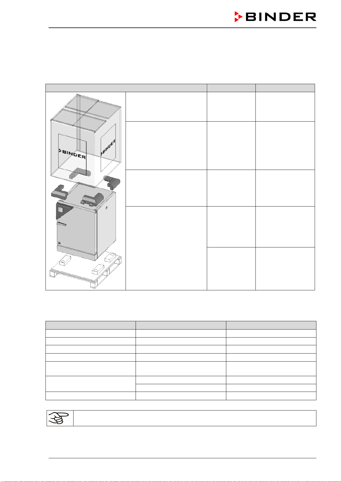
CB-S / CB-S-UL (E7) 06/2020 page 100/119
25. Disposal
25.1 Disposal of the transport packing
25.1.1 Outer chamber packing
Packing element
Material
Disposal
Straps to fix packing on pallet
(no image)
Plastic Plastic recycling
Shipping box Cardboard Paper recycling
Edge stuffing, top PE foam Plastic recycling
Pallet with foamed plastic
stuffing
PE foam Plastic recycling
Solid wood
(IPPC standard)
Wood recycling
25.1.2 Packing inside the chamber, equipment
Packing element
Material
Disposal
Door protection
PE foam
Plastic recycling
Packing box equipment
Cardboard
Paper recycling
Insulating air cushion foil
PE foil
Plastic recycling
Paperboard
Cardboard
Paper recycling
Silica gel bag Paper with silica gel
Do not open. Dispose of with
normal waste
Sensor packing
Cardboard
Paper recycling
PE foam
Plastic recycling
Bag for operating manuals
PE foil
Plastic recycling
If recycling is not possible, all packing parts can also be disposed of with normal waste.
CB-S / CB-S-UL (E7) 06/2020 page 101/119
25.2 Decommissioning
• Turn off the main power switch (2) and disconnect the chamber from the power supply (pull the power
plug).
• Turn off the CO
2
supply. Remove the gas connection.
• Let the inner chamber sufficiently cool down before removing any parts.
• The water pan must not remain filled while the incubator is out of operation. Otherwise condensation
may occur on the inner surfaces, as well as in the injection and suction nozzle of the CO
2
sensor com-
partment. If condensation formation has occurred, drops of condensate would leak from the openings
of injection and suction nozzle of the CO
2
sensor. In this case, clean and dry the incubator running at
37 °C / 98.6 °F with doors open for at least one hour before loading it with samples. BINDER recom-
mends performing a hot air sterilization of the chamber before commissioning.
• Temporal decommissioning: See indications for appropriate storage, chap. 3.3.
• Final decommissioning: Dispose of the chamber as described in chap. 25.3 to 25.5.
When restarting the chamber, please pay attention to the corresponding information in chap. 6.3.
25.3 Disposal of the chamber in the Federal Republic of Germany
According to Annex I of Directive 2012/19/EU of the European Parliament and of the Council on waste
electrical and electronic equipment (WEEE), BINDER devices are classified as “monitoring and control
instruments” (category 9) only intended for professional use“. They must not be disposed of at public col-
lecting points.
The chambers bear the symbol for the marking of electrical and electronic equipment man-
ufactured / placed on the market in the EU after 13 August 2005 and be disposed of in sep-
arate collection accordi
ng to Directive 2012/19/EU on waste electrical and electronic
equipment (WEEE) and German national law for electrical and electronic equipment (El-
ektro- und Elektronikgerätegesetz, ElektroG). WEEE marking: crossed-out wheeled bin with
solid bar under. A significant part of the materials must be recycled in order to protect the
environment.
At the end of the device’s service life, have the chamber disposed of according to the German national
law for electrical and electronic equipment (Elektro- und Elektronikgerätegesetz, ElektroG from 20 Octo-
ber 2015, BGBl. I p. 1739) or contact BINDER service who will organize taking back and disposal of the
chamber according to the German national law for electrical and electronic equipment (Elektro- und El-
ektronikgerätegesetz, ElektroG from 20 October 2015, BGBl. I p. 1739).
NOTICE
Danger of violation against existing law if not disposed of properly.
∅ Do NOT dispose of BINDER devices at public collecting points.
Have the device disposed of professionally at a recycling company which is certified
according to the German national law for electrical and electronic equipment (Elektro-
und Elektronikgerätegesetz, ElektroG from 20 October 2015, BGBl. I p. 1739).
or
Instruct BINDER Service to dispose of the device. The general terms of payment and
delivery of BINDER GmbH apply, which were valid at the time of purchasing the cham-
ber.
Certified companies disassemble waste (used) BINDER equipment in primary substances for recycling
according to Directive 2012/19/EU. The devices must be free from toxic, infectious or radioactive sub-
stances in order to eliminate any health hazards to the employees of the recycling companies.
CB-S / CB-S-UL (E7) 06/2020 page 102/119
Prior to handing the chamber over to a recycling company, it is the user’s responsibility that it
is free from toxic, infectious or radioactive substances.
• Prior to disposal, clean all introduced or residual toxic substances from the chamber.
• Prior to disposal, disinfect the chamber
from all sources of infection. Be aware that sources
of infection may also be located outside the inner chamber.
• If you cannot safely remove all toxic substances and sources of infection from the chamber
,
dispose of it as “special” waste according to national law.
• Fill out the contamination clearance certificate (chap. 29) and enclose it with the chamber.
WARNING
Danger of intoxication and infection through contamination of the chamber with
toxic, infectious or radioactive substances.
Damages to health.
∅ NEVER take a chamber contaminated with toxic substances or sources of infection for
recycling according to Directive 2012/19/EU.
Prior to disposal, remove all toxic substances and sources of infection from the cham-
ber.
A chamber from which all toxic substances or sources of infection cannot be safely
removed must be considered as “special” waste according to national law. Dispose of it
accordingly.
25.4 Disposal of the chamber in the member states of the EU except for the Fed-
eral Republic of Germany
According to Annex I of Directive 2012/19/EU of the European Parliament and of the Council on waste
electrical and electronic equipment (WEEE), BINDER devices are classified as “monitoring and control
instruments” (category 9) only intended for professional use“. They must not be disposed of at public col-
lecting points.
The chambers bear the symbol for the marking of electrical and electronic equipment man-
ufactured / placed on the market in the EC after 13 August 2005 and be disposed of in
separate collection according to the Directive 2012/19/EU on waste electrical and electron-
ic equipment (WEEE). WEEE marking: crossed-out wheeled bin with solid bar under.
At the end of the device’s service life, notify the distributor who sold you the device, who
will take back and dispose of the chamber according to the Directive 2012/19/EU on waste
electrical and electronic equipment (WEEE).
NOTICE
Danger of violation against existing law if not disposed of properly.
∅ Do NOT dispose of BINDER devices at public collecting points.
Have the device disposed of professionally at a recycling company that is certified ac-
cording to conversion of the Directive 2012/19/EU into national law.
or
Instruct the distributor who sold you the device to dispose of it. The agreements apply
that were agreed
with the distributor when purchasing the chamber (e.g. his general
terms of payment and delivery).
If your distributo
r is not able to take back and dispose of the chamber, please contact
BINDER service.
CB-S / CB-S-UL (E7) 06/2020 page 103/119
Certified companies disassemble waste (used) BINDER equipment in primary substances for recycling
according to Directive 2012/19/EU. The devices must be free from toxic, infectious or radioactive sub-
stances in order to eliminate any health hazards to the employees of the recycling companies.
Prior to handing the chamber over to a recycling company, it is the user’s responsibility that it
is free from toxic, infectious or radioactive substances.
• Prior to disposal, clean all introduced or residual toxic substances from the chamber.
• Prior to disposal, disinfect the chamber
from all sources of infection. Be aware that sources
of infection may also be located outside the inner chamber.
• If you cannot safely remove all sources of infection and toxic substances from the chamber
,
dispose of it as “special” waste according to national law.
• Fill out the contamination clearance certificate (chap. 29) and enclose it with the chamber.
WARNING
Danger of intoxication and infection through contamination of the chamber with
toxic, infectious or radioactive substances.
Damages to health.
∅ NEVER take a chamber contaminated with toxic substances or sources of infection for
recycling according to Directive 2012/19/EU.
Prior to disposal, remove all toxic substances and sources of infection from the cham-
ber.
A chamber from which all toxic substances or sources of infection cannot be safely
removed must be considered as “special” waste according to national law. Dispose of it
accordingly.
25.5 Disposal of the chamber in non-member states of the EU
NOTICE
Danger of violation against existing law if not disposed of properly.
Alteration of the environment.
For final decommissioning and disposal of the chamber, please contact BINDER ser-
vice.
Follow the statutory regulations for appropriate, environmentally friendly disposal.
The main board of the CO
2
incubator includes a lithium cell. Please dispose of it according to national
regulations.
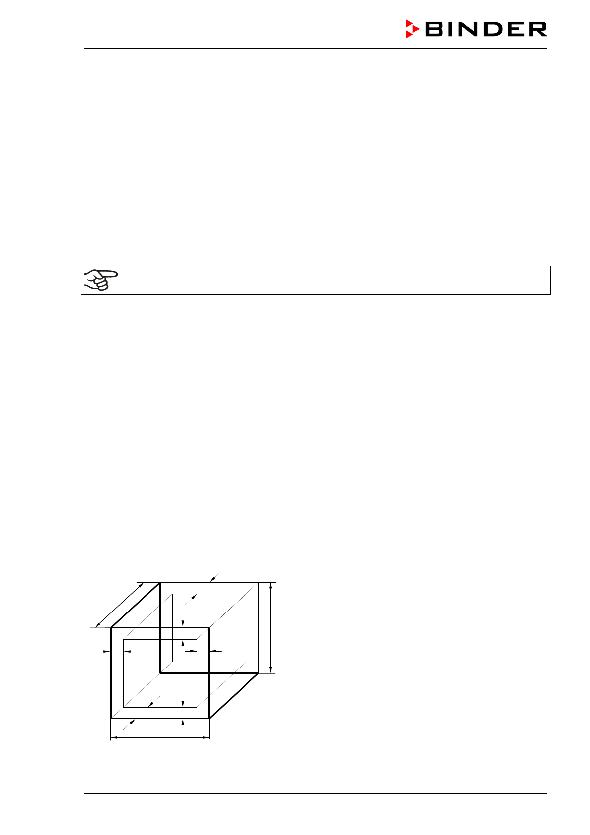
CB-S / CB-S-UL (E7) 06/2020 page 104/119
26. Technical description
26.1 Factory calibration and adjustment
This chamber was calibrated and adjusted in the factory. Calibration and adjustment were performed
using standardized test instructions, according to the QM DIN EN ISO 9001 system applied by BINDER
(certified since December 1996 by TÜV CERT). All test equipment used is subject to the administration of
measurement and test equipment that is also a constituent part of the BINDER QM DIN EN ISO 9001
systems. They are controlled and calibrated to a DKD-Standard at regular intervals.
A record of this calibration and adjustment is part of the BINDER test certificate of the chamber.
Adjustment in factory:
• Temperature: 37 °C / 98.6 °F measured in the center of the usable volume
• CO
2
: 0 vol.-% CO
2
(100 vol.-% N
2
) and 5 vol.-% CO
2
(sensor head directly exposed to analyzed test
gas)
Repeated calibrations are recommended in periods of 12 months.
Suitable reference methods applicable for the user for comparison between reference measuring results
and the display readings of the controller(s) are explained in chap. 19.
During factory calibration and adjustment, an electronic temperature measuring and display device is
used, which is traceable to an acknowledged standards/calibration institution (DKD or PTB for Germany),
bearing a valid calibration certificate.
During factory calibration and adjustment, test gases with an analyzed concentration and with adapted
flow quantity serve to calibrate the sensor system for CO
2
. The sensor head is exposed directly to the test
gas.
26.2 Over current protection
A miniature fuse accessible from the outside protects the device against over current. The miniature fuse
is located at the rear of the chamber below the strain relief of the power cord. The fuse holder is equipped
with a fuse clip 5mm x 20 mm. Replace the fuse only with a substitute of the same ratings. Refer to the
technical data of the respective device type. If the fuse is blown, please inform an electronic engineer or
BINDER service.
26.3 Definition of usable volume
The usable volume illustrated below is calculated as follows:
c
c
b
a
C
B
A
b
a
A, B, C = internal dimensions (W, H, D)
a, b, c = wall separation
a = 0.1*A
b = 0.1*B
c = 0.1*C
V
USE
= (A - 2 * a) * (B - 2 * b) * (C - 2 * c)
Figure 22: Determination of the useable volume
CB-S / CB-S-UL (E7) 06/2020 page 105/119
The technical data refers to the so defined usable volume.
Do NOT place samples outside this usable volume.
Do NOT load this volume by more than half to enable sufficient airflow inside the CO
2
incuba-
tor.
Do NOT divide the usable volume into separate parts with large area samples.
Do NOT place samples too close to each other in order to permit circulation between them
and thus obtain a homogenous distribution of temperature and CO
2
.
26.4 CB-S / CB-S-UL technical data
Chamber size
170
260
Exterior dimensions
Width, net
mm / inch
680 / 26.77
740 / 29.13
Height including feet
mm / inch
870 / 34.25
1025 / 40.35
Depth, net
mm / inch
715 / 28.15
775 / 30.51
Depth including door handle, I-triangle, and
connections
mm / inch 795 / 31.30 855 / 33.66
Wall clearance rear (minimum)
mm / inch
100 / 3.94
100 / 3.94
Wall clearance side (minimum)
mm / inch
50 / 1.97
50 / 1.97
Doors
Number of doors
1
1
Number of inner glass doors
1
1
Interior dimensions
Width
mm / inch
560 / 22.05
620 / 24.41
Height
mm / inch
600 / 23.62
750 / 29.53
Depth
mm / inch
500 / 19.68
560 / 22.05
Interior volume
l / cu.ft.
170 / 6.00
260 / 9.18
Shelves
Number of shelves, series
2
2
Number of shelves, max.
6
8
Size of shelf, width x depth
mm x mm
inch x inch
551 x 442
21.69 x 17.40
614 x 502
24.17 x 19.76
Maximum load per rack
kg / lbs
10 / 22
10 / 22
Maximum permitted total load
kg / lbs
40 / 88
40 / 88
Weight
Weight (empty)
kg / lbs
96 / 212
116 / 256
Temperature data
Temperature range, 6 °C / 10.8 °F above ambient,
up to
°C / °F 50 / 122 50 / 122
Temperature fluctuation
≤ +/- K
0.1
0.1
Temperature uniformity (variation) at 37 °C/ 98.6
°F
+/- K 0.3 0.4
Recovery time after door open for 30 sec
at 37 °C / 98.6°F
minutes 8 9
Humidity data
Humidity range
% r.h.
90 to 95
90 to 95
CB-S / CB-S-UL (E7) 06/2020 page 106/119
Chamber size
170
260
CO
2
data
CO
2
range
vol.-% CO
2
0 to 20
0 to 20
Setting accuracy
vol.-% CO
2
0.1
0.1
CO
2
fluctuation
vol.-% CO
2
0.1
0.1
Recovery time after door open for 30 sec
at 5 vol.-% CO
2
minutes 5 5
CO
2
measurement
IR
IR
Connection hose nozzle DN6 for CO
2
Connection to the chamber for hose with internal
diameter
mm / inch 6 / 0.24 6 / 0.24
Electrical data (model versions C170-230V, CBS260-230V)
IP system of protection acc. to EN 60529
IP
20
20
Nominal voltage
(+/-10%)
at 50 Hz power frequency
V
200-230
at 60 Hz power frequency
V
200-230
Current type
1N~
1N~
Nominal power
kW
1.30
1.30
Power plug (IEC connector plug)
Grounded plug
IEC 7/7
Grounded plug
IEC 7/7
Installation category acc. to IEC 61010-1
II
II
Pollution degree acc. to IEC 61010-1
2
2
Chamber fuse
5x20mm / semi time-lag / 10 A
Different electrical data for C-UL constructed for the USA and Canada
(model versions C170UL-120V, CBS260UL-120V)
Nominal voltage (+/-10 %) at 50 Hz power frequen-
cy
V
100-120
100-120
Nominal voltage (+/-10 %) at 60 Hz power frequen-
cy
V
100-120
100-120
Power plug (IEC connector plug)
NEMA
5-20P
5-20P
Chamber fuse
6.3 X 32 mm / 250V / super-time-lag TT / 16A
Environment-specific data
Noise level (mean value)
dB (A)
41
41
Energy consumption at 37 °C / 98.6°F
Wh/h
45
55
The recovery times of the gas concentrations inside the chamber following the door being opened coin-
cide with a connection pressure of 2.0 bar / 29 psi. Decreasing supply pressure results in longer recovery
times.
All technical data is specified for unloaded chambers with standard equipment at an ambient temperature
of +22 °C +/- 3 °C / 71.6 °F +/- 5.4 °F and a power supply voltage fluctuation of +/-10%. The technical
data is determined in accordance to BINDER Factory Standard Part 2:2015 and DIN 12880:2007.
All indications are average values, typical for chambers produced in series. We reserve the right
to change technical specifications at any time.
26.5 Important conversion data for non-SI units
1 ft = 0.305 m = 0.000305 km
1 m = 100 cm = 3.28 ft = 39.37 inch
1 km = 1000 m = 3280.83 ft
1 mbar = 0.0145 psi
CB-S / CB-S-UL (E7) 06/2020 page 107/119
26.6 Conversion table for gas inlet pressures, bar – psi
bar
psi
bar
psi
bar
psi
1
14.5
3
43.5
5
72.5
1.5
21.7
3.5
50.7
5.5
79.7
2
29.0
4
58.0
6
87.0
2.5
36.3
4.5
65.2
26.7 Equipment and options (extract)
To operate the chamber, use only original BINDER accessories or accessories / components
from third-party suppliers authorized by BINDER. The user is responsible for any risk arising
from using unauthorized accessories.
Regular equipment
Microprocessor controller RD4 for temperature and CO
2
CO
2
infra-red absorption measuring system
Hot-air sterilization at 180 °C / 356°F
Gas mixing head
Ethernet interface for computer communication
USB interface
Weldless deep-drawn inner chamber made of stainless steel V2A (German material no. 1.4301,
US equivalent AISI 304), polished
Electronic error auto-diagnosis system with zero-voltage relay alarm output
Safety controller (temperature safety device class 3.1 acc. to DIN 12880:2007)
Tightly closing inner glass door
2 perforated shelves, stainless steel (German material no. 1.4016, US equivalent AISI 430)
Options / accessories
Perforated shelf, stainless steel
Door hinged left (option only available when ordering the chamber, no retrofitting)
Silicone access ports, closable with 2 silicone plugs 30 mm / 1.18 in , rear, left or right side
Analog outputs 4-20mA for temperature and CO
2
, with DIN socket 6-poles, DIN plug included
BINDER Data logger kit T 220
Base on castors
Flat stacking frame
Gas cylinder connection kit
Pressure reducer
Cleaning kit (neutral cleaning agent, disinfection spray and lint-free disposable wipes, protective gloves
and safety goggles)
Calibration of temperature and CO
2
including certificate
Spatial temperature measurement including certificate
Spatial temperature measurement acc. to DIN 12880:2007 including certificate
Qualification folder
CB-S / CB-S-UL (E7) 06/2020 page 108/119
26.8 Options, accessories, and spare parts (extract)
BINDER GmbH is responsible for the safety features of the chamber only, provided skilled
electricians or qualified personnel authorized by BINDER perform all maintenance and repair,
and if components relating to chamber safety are replaced in the event of failure with original
spare parts. The user is responsible for any risks arising from using unauthorized accesso-
ries/components.
Description
Art. no.
Art. no.
Perforated shelf, stainless steel
6004-0137
6004-0197
Base on castors
9051-0029
9051-0044
Flat stacking frame
9051-0035
9051-0039
Door gasket for outer door
6005-0275
6005-0296
Door gasket for glass door
6005-0508
6005-0314
Water pan
4022-0325
4022-0410
Description
Art. no.
Chamber fuse 5x20mm 250V 10A semi time-lag (M) (for 230V chambers)
5006-0012
Chamber fuse 6.3 x 32 mm 250V 16A time-lag (T) (for UL chambers)
5006-0033
CO
2
sensor
5002-0066
Filter cap for CO
2
sensor
6014-0033
Gas fine filter
8009-0369
Power cable with IEC connector plug for EU
5023-0222
Power cable with IEC connector plug for Switzerland
8012-0218
Power cable with IEC connector plug for England
8012-0220
Power cable with IEC connector plug for USA
5023-0220
Gas cylinder connection kit for CO
2
8012-0014
Pressure reducer
6013-0016
Calibration certificate for temperature and CO
2
8012-0228
Cleaning kit (neutral cleaning agent, disinfection spray and lint-free disposable
wipes), protective gloves and safety goggles
8012-0503
Neutral cleaning agent, 1 kg
1002-0016
For information on components not listed here, please contact BINDER Service.
Validation service
Art. no.
Qualification folder IQ-OQ (printed version)
7007-0001
Qualification folder IQ-OQ (digital version)
7057-0001
Qualification folder IQ-OQ-PQ (printed version)
7007-0005
Qualification folder IQ-OQ-PQ (digital version)
7057-0005
Execution of IQ-OQ
DL410200
Execution of IQ-OQ-PQ
DL440500
Calibration service
Art. no.
Calibration of temperature including certificate
8012-1132
Calibration of temperature and CO
2
including certificate
8012-1235
Spatial temperature measurement including certificate (9 measuring points)
8012-1550
Spatial temperature measurement including certificate (15-18 measuring points)
8012-1571
Spatial temperature measurement including certificate (27 measuring points)
8012-1592
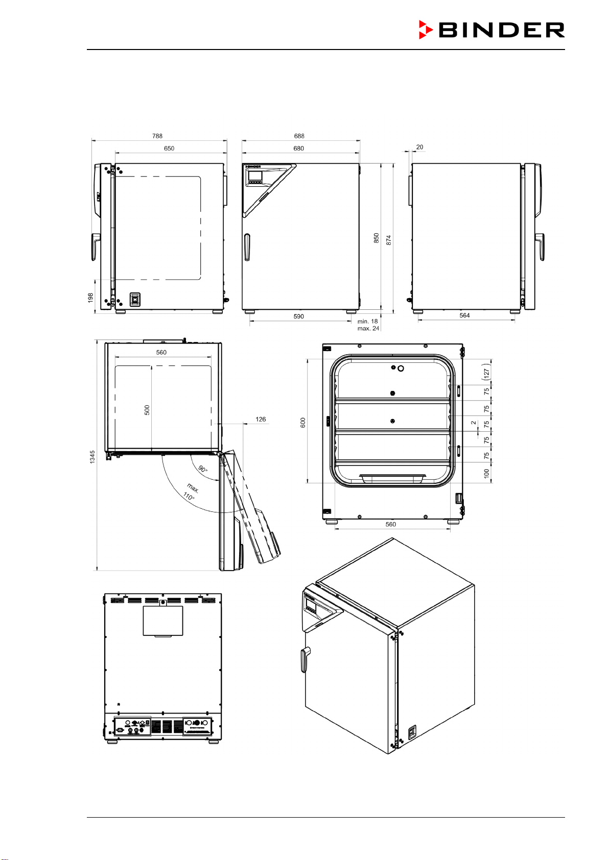
CB-S / CB-S-UL (E7) 06/2020 page 109/119
26.9 Dimensions
CB-S / CB-S-UL 170:
[Dimensions in mm]
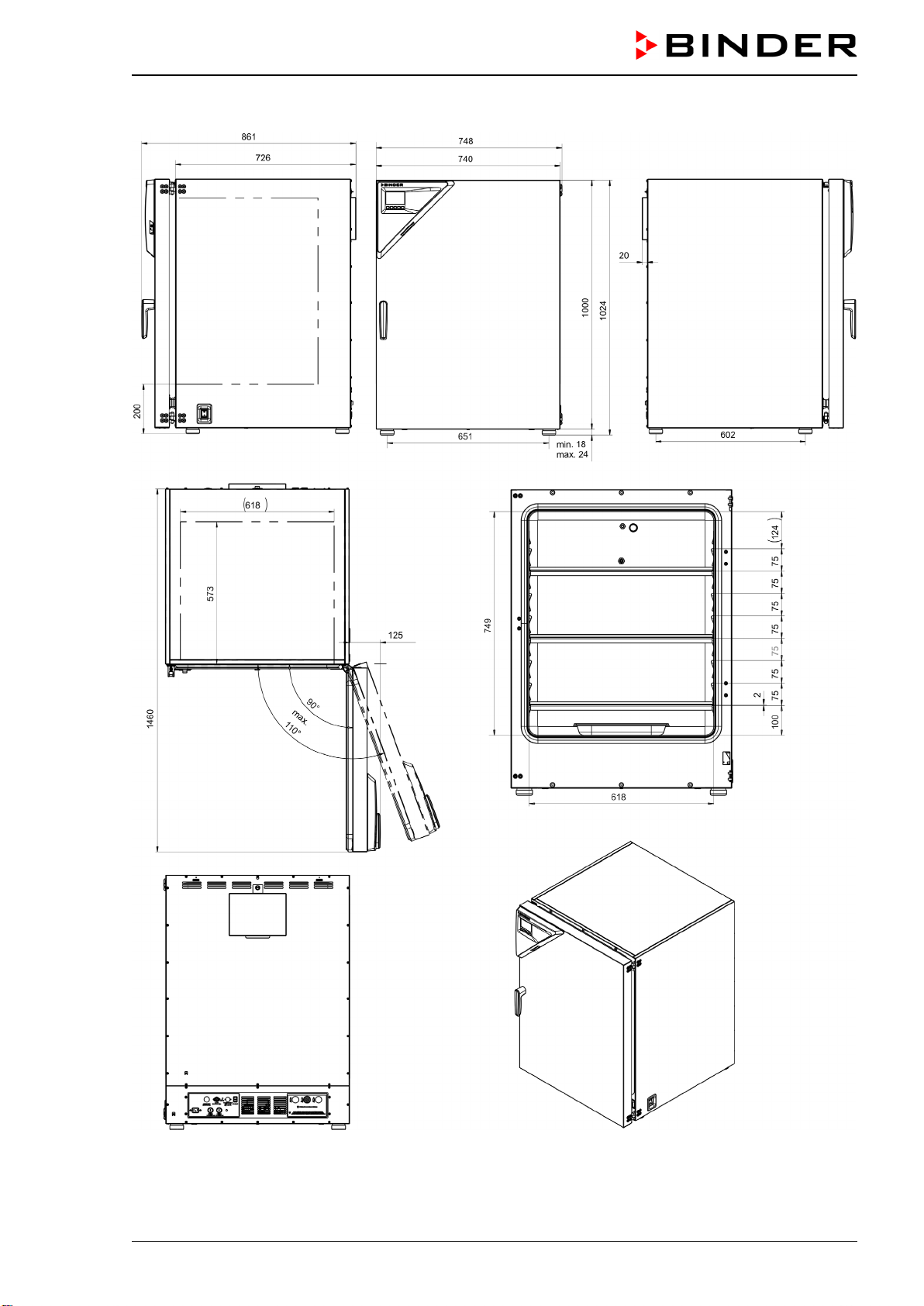
CB-S / CB-S-UL (E7) 06/2020 page 110/119
CB-S / CB-S-UL 260:
[Dimensions in mm]
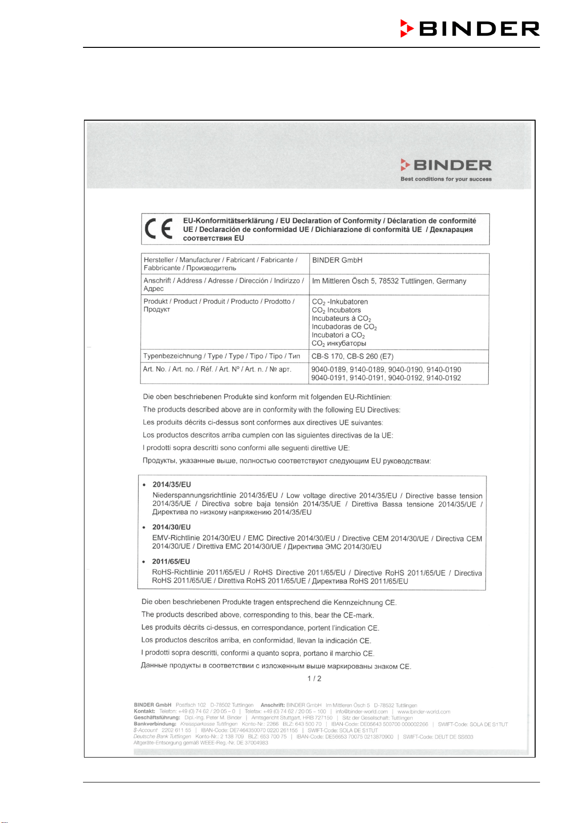
CB-S / CB-S-UL (E7) 06/2020 page 111/119
27. Certificates and declarations of conformity
27.1 EU Declaration of Conformity
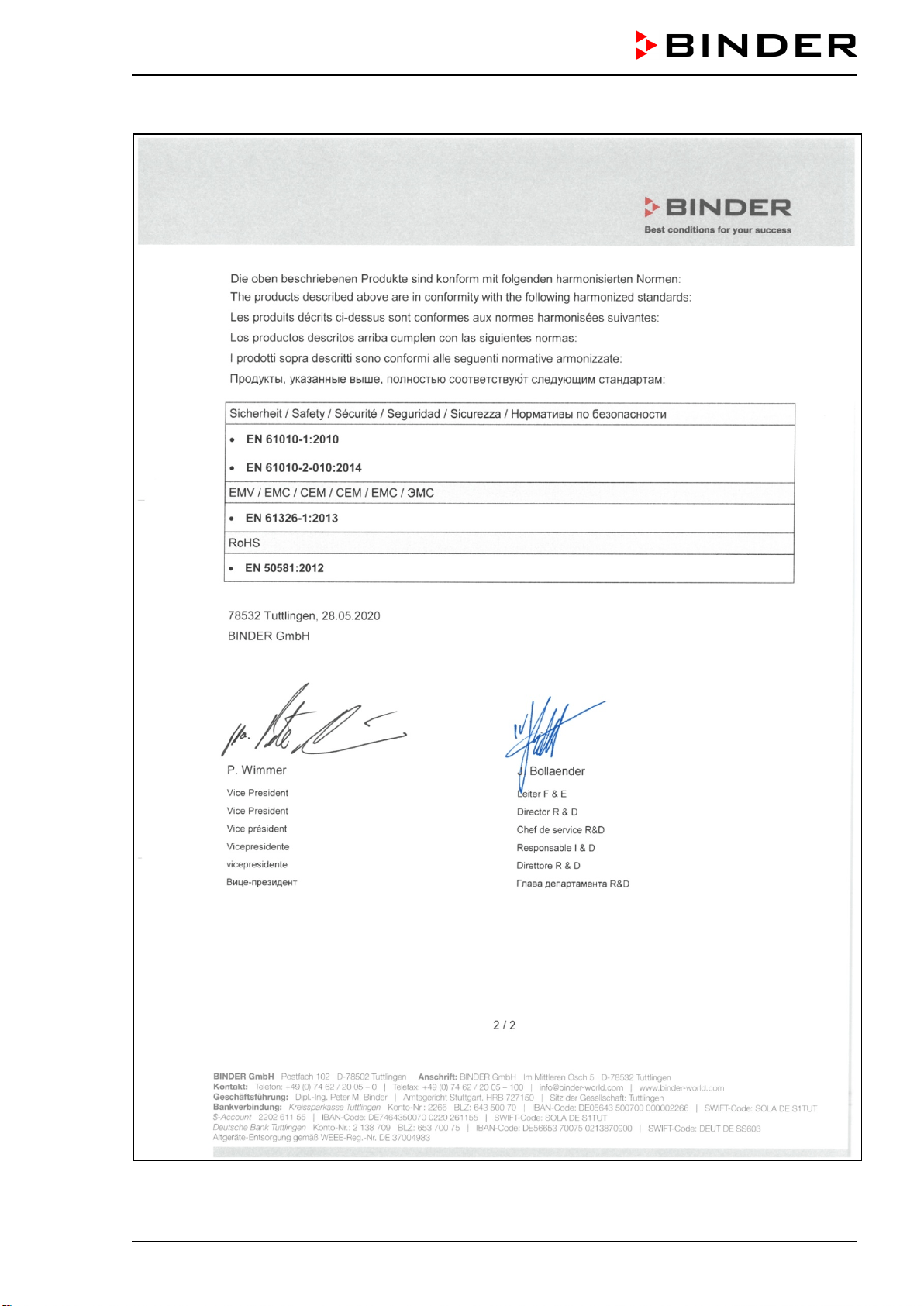
CB-S / CB-S-UL (E7) 06/2020 page 112/119
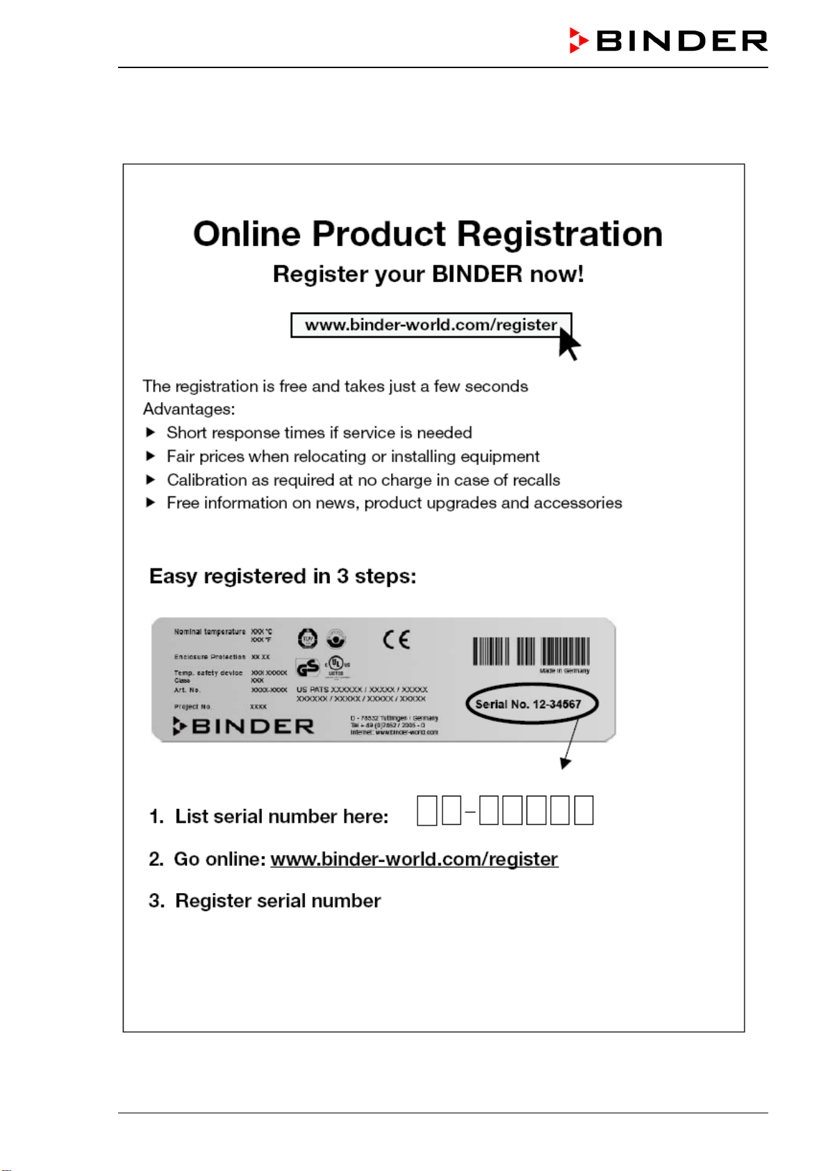
CB-S / CB-S-UL (E7) 06/2020 page 113/119
28. Product registration
CB-S / CB-S-UL (E7) 06/2020 page 114/119
29. Contamination clearance certificate
Unbedenklichkeitsbescheinigung
29.1 For chambers located outside the USA and Canada
Declaration regarding safety and health
Erklärung zur Sicherheit und gesundheitlichen Unbedenklichkeit
The German Ordinance on Hazardous Substances (GefStofV), and the regulations regarding safety at
the workplace require that this form be filled out for all products that are returned to us, so that the safety
and the health of our employees can be guaranteed.
Die Sicherheit und Gesundheit unserer Mitarbeiter, die Gefahrstoffverordnung GefStofV und die Vorschriften zur
Sicherheit am Arbeitsplatz machen es erforderlich, dass dieses Formblatt für alle Produkte, die an uns zurückges-
chickt wird.
Note: A repair is not possible without a completely filled out form.
Ohne Vorliegen des vollständig ausgefüllten Formblattes ist eine Reparatur nicht möglich
.
• A completely filled out form must be transmitted via Fax (+49 (0) 7462 2005 93555) or by letter in ad-
vance, so that this information is available before the equipment/component part arrives. A second
copy of this form must accompany the equipment/component part. In addition, the carrier should be
notified.
Eine vollständig ausgefüllte Kopie dieses Formblattes soll per Telefax (Nr. +49 (0) 7462 2005 93555) oder Brief
vorab an uns gesandt werden, so dass die Information vorliegt, bevor das Gerät/Bauteil eintrifft. Eine weitere
Kopie soll dem Gerät/Bauteil beigefügt sein. Ggf. ist auch die Spedition zu informieren.
• Incomplete information or non-conformity with this procedure will inevitably lead to substantial delays
in processing. Please understand the reason for this measure, which lies outside our area of influence
and will help us to speed up this procedure.
Unvollständige Angaben oder Nichteinhalten dieses Ablaufs führen zwangsläufig zu beträchtlichen Verzöger-
ungen in der Abwicklung. Bitte haben Sie Verständnis für Maßnahmen, die außerhalb unserer Einflussmöglich-
keiten liegen und helfen Sie mit, den Ablauf beschleunigen.
• Please print and fill out this form completely.
Bitte unbedingt vollständig ausfüllen!
1. Unit/ component part / type: / Gerät / Bauteil / Typ:
2. Serial No./ Serien-Nr.:
3. Details about utilized substances / biological substances / Einzelheiten über die eingesetzten
Substanzen/biologische Materialien:
3.1 Designations / Bezeichnungen:
a) ____________________________________________________________________________
b) ____________________________________________________________________________
c) ____________________________________________________________________________
3.2 Safety measures required for handling these substances / Vorsichtsmaßnahmen beim Um-
gang mit diesen Stoffen:
a) ____________________________________________________________________________
b) ____________________________________________________________________________
c) ____________________________________________________________________________

CB-S / CB-S-UL (E7) 06/2020 page 115/119
3.3 Measures to be taken in case of skin contact or release into the atmosphere / Maßnahmen
bei Personenkontakt oder Freisetzung:
a) ____________________________________________________________________________
b) ____________________________________________________________________________
c) ____________________________________________________________________________
d) ____________________________________________________________________________
3.4 Other important information that must be taken into account / Weitere zu beachtende und
wichtige Informationen:
a) ____________________________________________________________________________
b) ____________________________________________________________________________
c) ____________________________________________________________________________
4. Declaration on the risk of these substances (please checkmark the applicable items) /
Erklärung zur Gefährlichkeit der Stoffe (bitte Zutreffendes ankreuzen) :
4.1 For non toxic, non radioactive, biologically harmless materials / für nicht giftige, nicht radi-
oaktive, biologisch ungefährliche Stoffe:
We hereby guarantee that the above-mentioned unit / component part… /
Wir versichern, dass o.g.
Gerät/Bauteil...
Has not been exposed to or contains any toxic or otherwise hazardous substances /
weder giftige noch
sonstige gefährliche Stoffe enthält oder solche anhaften.
That eventually generated reaction products are non-toxic and also do not represent a hazard /
auch
evtl. entstandene Reaktionsprodukte weder giftig sind noch sonst eine Gefährdung darstellen.
Eventual residues of hazardous substances have been removed /
evtl. Rückstände von Gefahrstoffen
entfernt wurden.
4.2 For toxic, radioactive, biologically harmful or hazardous substances, or any other hazard-
ous materials /
für giftige, radioaktive, biologisch bedenkliche bzw. gefährliche Stoffe oder
anderweitig gefährliche Stoffe.
We hereby guarantee that … /
Wir versichern, dass …
The hazardous substances, which have come into contact with the above-mentioned equip-
ment/component part, have been completely listed under item 3.1 and that all information in this re-
gard is complete /
die gefährlichen Stoffe, die mit dem o.g. Gerät/Bauteil in Kontakt kamen,
in 3.1 aufgelistet
sind und alle Angaben vollständig sind.
That the unit /component part has not been in contact with radioactivity /
das Gerät/Bauteil nicht mit Ra-
dioaktivität in Berührung kam
5. Kind of transport / transporter / Transportweg/Spediteur:
Transport by (means and name of transport company, etc.)
Versendung durch (Name Spediteur o.ä.)
__________________________________________________________________________________
Date of dispatch to BINDER GmbH /
Tag der Absendung an BINDER GmbH:
___________________________________________________________________________________
CB-S / CB-S-UL (E7) 06/2020 page 116/119
We hereby declare that the following measures have been taken / Wir erklären, dass folgende
Maßnahmen getroffen wurden:
Hazardous substances were removed from the unit including component parts, so that no hazard ex-
ists for any person in the handling or repair of these items /
das Gerät/Bauteil wurde von Gefahrstoffen be-
freit, so dass bei Handhabung/Reparaturen für die betreffenden Person keinerlei Gefährdung besteht
The unit was securely packaged and properly identified /
das Gerät wurde sicher verpackt und vollständig
gekennzeichnet.
Information about the hazardousness of the shipment (if required) has been provided to the trans-
porter /
der Spediteur wurde (falls vorgeschrieben) über die Gefährlichkeit der Sendung informiert.
We hereby commit ourselves and guarantee that we will indemnify BINDER GmbH for all damages that
are a consequence of incomplete or incorrect i
nformation provided by us, and that we will exempt
BINDER GmbH from eventual damage claims by third parties./
Wir versichern, dass wir gegenüber BINDER
für jeden Schaden, der durch unvollständige und unrichtige Angaben entsteht, haften und BINDER gegen eventuell
entstehende Schadenansprüche Dritter freistellen.
We are aware that, in accordance with Article 823 of the German Civil Code (BGB), we are directly liable
with regard to third parties, in this instance especially the employees of BINDER GmbH, who
have been
entrusted with the handling / repair of the unit / component. / Es ist uns bekannt, dass wir gegenüber Dritten –
hier insbesondere mit der Handhabung/Reparatur des Geräts/des Bauteils betraute Mitarbeiter der Firma BINDER -
gemäß §823 BGB direkt haften
Name: _______________________________________________________________________
Position/Title: _______________________________________________________________________
Date /
Datum: _______________________________________________________________________
Signature /
Unterschrift: _______________________________________________________________
Company stamp /
Firmenstempel:
Equipment that is returned to the factory for repair must be accompanied by a completely filled
out contamination clearance certificate. For service and maintenance on site, you must submit
such a contamination clearance certificate to the service technician before the start of any
work. No repair or maintenance of the equipment is possible, without a properly filled out con-
tamination clearance certificate.

CB-S / CB-S-UL (E7) 06/2020 page 117/119
29.2 For chambers in the USA and Canada
Product Return Authorization Request
Please complete this form and the Customer Decontamination Declaration (next 2 pages) and attach the
required pictures. E-mail to: IDL_SalesOrderProcessing_USA@binder-world.com
After we have received and reviewed the complete information we will decide on the issue of a RMA
number. Please be aware that size specifications, voltage specifications as well as performance specifi-
cations are available on the internet at www.binder-world.us at any time.
Take notice of shipping laws and regulations.
Please fill:
Reason for return request Duplicate order
Duplicate shipment
Demo Page one completed by sales
Power Plug / Voltage 115V / 230 V / 208 V / 240V
Size does not fit space
Transport Damage Shock watch tripped? (pictures)
Other (specify below)
_____________________
Is there a replacement PO? Yes No
If yes -> PO #
If yes -> Date PO placed
Purchase order number
BINDER model number
BINDER serial number
Date unit was received
Was the unit unboxed? Yes No
Was the unit plugged in? Yes No
Was the unit in operation? Yes No
Pictures of unit attached?
Pictures of Packaging at-
tached?
Yes No
Yes No
Pictures have to be attached!
Customer Contact Information Distributor Contact Information
Name
Company
Address
Phone
E-mail
CB-S / CB-S-UL (E7) 06/2020 page 118/119
Customer (End User) Decontamination Declaration
Health and Hazard Safety declaration
To protect the health of our employees and the safety at the workplace, we require that this form is com-
pleted by the user for all products and parts that are returned to us. (Distributors or Service Organizations
cannot sign this form)
NO RMA number will be issued without a completed form. Products or parts returned to our
NY warehouse without a RMA number will be refused at the dock.
A second copy of the completed form must be attached to the outside of the shipping box.
1. Unit/ component part / type
:
2. Serial No.
3. List any exposure to hazardous liquids, gasses or substances and radioactive material
3.1 List with MSDS sheets attached where available or needed
(if there is not enough space available below, please attach a page):
a) ____________________________________________________________________________
b) ____________________________________________________________________________
c) ____________________________________________________________________________
3.2 Safety measures required for handling the list under 3.1
a) ____________________________________________________________________________
b) ____________________________________________________________________________
c) ____________________________________________________________________________
3.3 Measures to be taken in case of skin contact or release into the atmosphere
:
a) ____________________________________________________________________________
b) ____________________________________________________________________________
c) ____________________________________________________________________________
d) ____________________________________________________________________________
3.4 Other important information that must be considered
:
a) ____________________________________________________________________________
b) ____________________________________________________________________________
c) ____________________________________________________________________________
CB-S / CB-S-UL (E7) 06/2020 page 119/119
4. Declaration of Decontamination
For toxic, radioactive, biologically and chemically harmful or hazardous substances, or any other
hazardous materials.
We hereby guarantee that
4.1 Any hazardous substances, which have come into contact with the above-mentioned equipment /
component part, have been completely listed under item 3.1 and that all information in this regard is
complete
.
4.2 That the unit /component part has not been in contact with radioactivity
4.3 Any Hazardous substances were removed from the unit / component part, so that no hazard exists
for a persons in the shipping, handling or repair of these returned unit
4.4 The unit was securely packaged in the original undamaged packaging and properly identified on the
outside of the packaging material with the unit designation, the RMA number and a copy of this dec-
laration.
4.5 Shipping laws and regulations have not been violated.
I hereby commit and guarantee that we will indemnify BINDER Inc. for all damages that are a
consequence of incomplete or incorrect information provided by us, and that we will indemnify
and hold harmless BINDER Inc. from eventual damage claims by third parties..
Name: _______________________________________________________________________
Position: _______________________________________________________________________
Company: _______________________________________________________________________
Address: _______________________________________________________________________
Phone #: _______________________________________________________________________
Email: _______________________________________________________________________
Date: _______________________________________________________________________
Signature: _______________________________________________________________________
Equipment returned to the NY warehouse for repair must be accompanied by a completed
customer decontamination declaration. For service and maintenance works on site, such a
customer decontamination declaration must be submitted to the service technician before the
start of work. No repair or maintenance of the equipment is possible without a completed form.