Issue 06/2020 Art. No. 7001-0365
Operating Manual
Translation of the original operating manual
MKF (E5)
Alternating climate chambers with program control
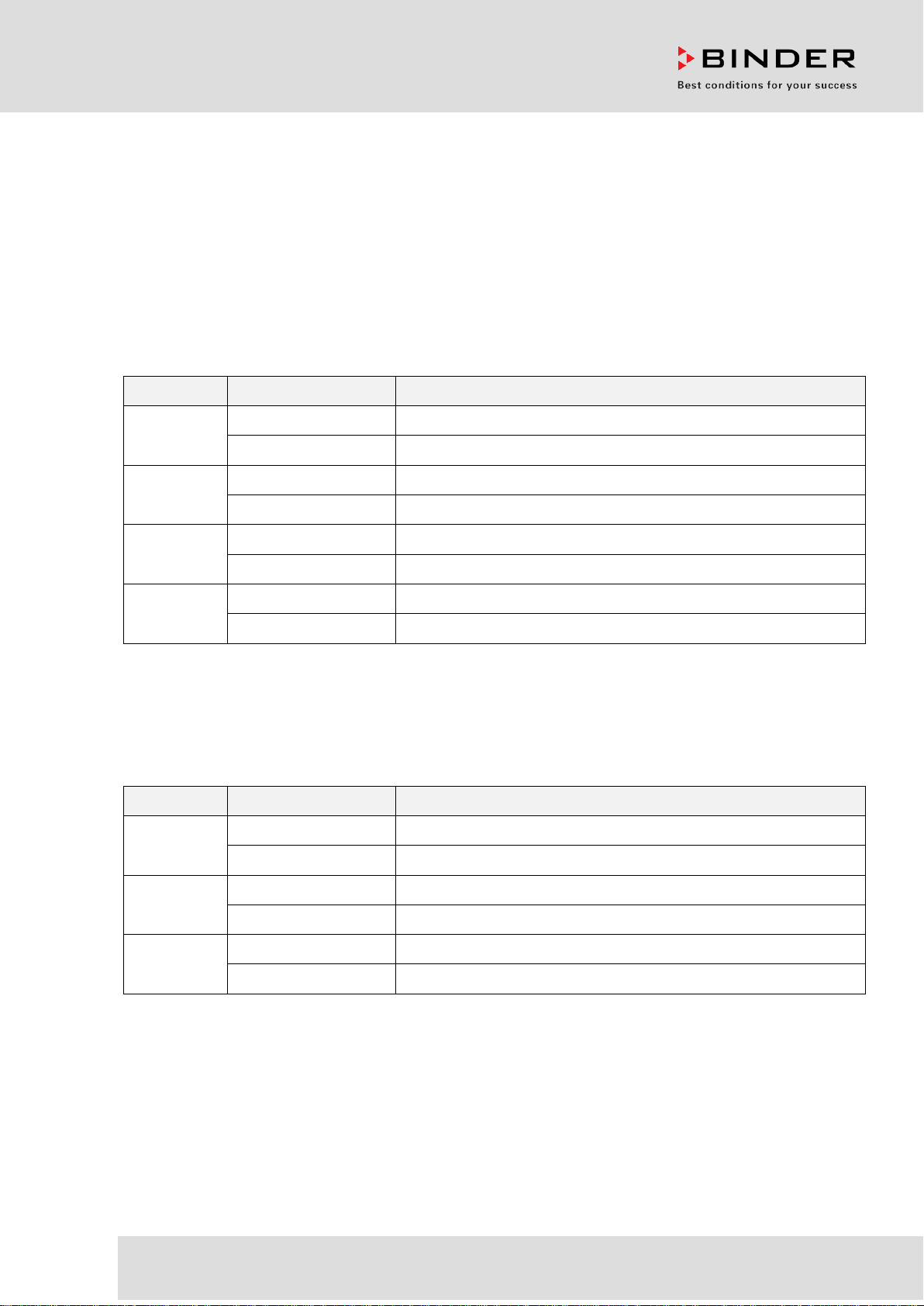
Model Model version
Art. No.
MKF 56 MKF056-230V 9020-0378, 9120-0378
MKF056-240V 9020-0389, 9120-0389
MKF 115
MKF115-400V
9020-0379, 9120-0379
MKF115-400V-C 9020-0357 (with voltage and frequency changer)
MKF 240
MKF240-400V
9020-0380, 9120-0380
MKF240-400V-C
9020-0358 (with voltage and frequency changer)
MKF 720 MKF720-400V 9020-0381, 9120-0381
MKF720-400V-C
9020-0359 (with voltage and frequency changer)
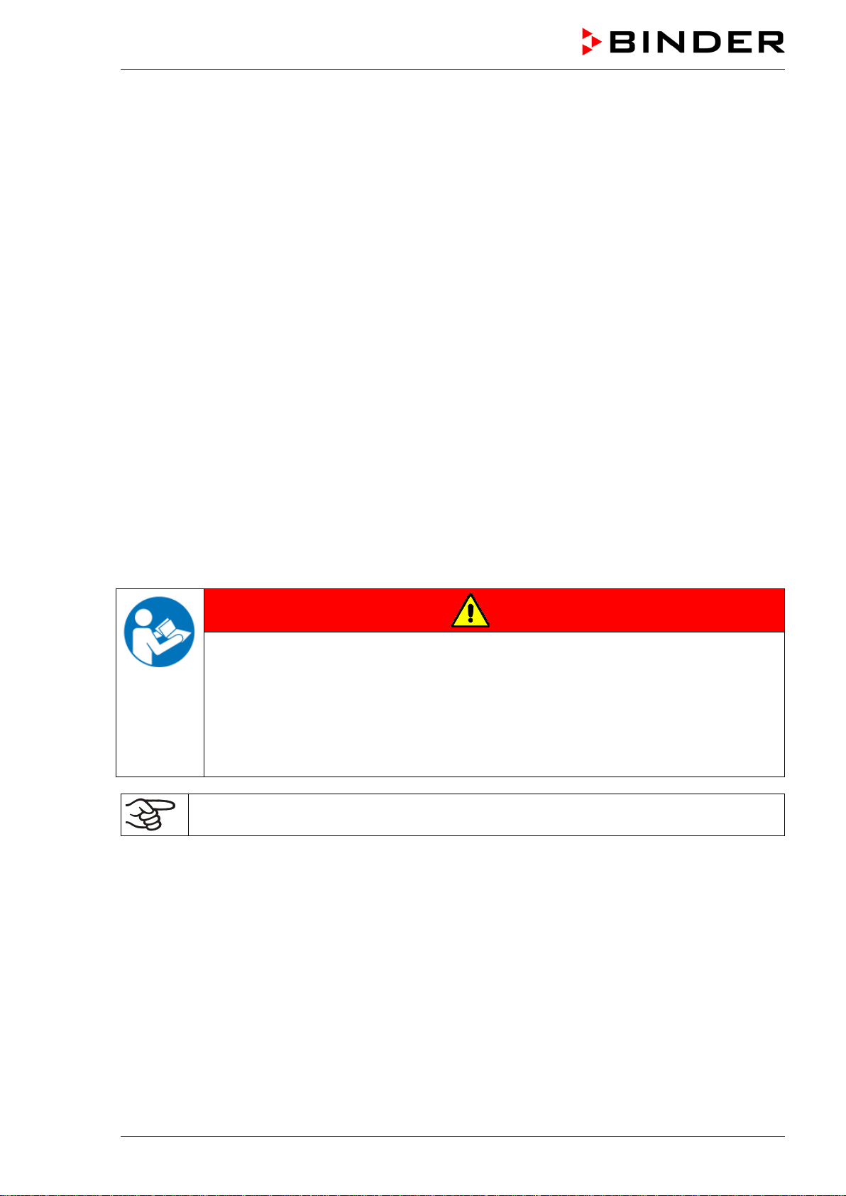
MKFT (E5)
Alternating climate chambers with deep temperature
with program control
Model Model version
Art. No.
MKFT 115 MKFT115-400V 9020-0382, 9120-0382
MKFT115-400V-C
9020-0362 (with voltage and frequency changer)
MKFT 240 MKFT240-400V 9020-0383, 9120-0383
MKFT240-400V-C
9020-0361 (with voltage and frequency changer)
MKFT 720
MKFT720-400V
9020-0384, 9120-0384
MKFT720-400V-C 9020-0360 (with voltage and frequency changer)
BINDER GmbH
Address: Post office box 102, 78502 Tuttlingen, Germany Phone: +49 7462 2005 0
Fax: +49 7462 2005 100 Internet: http://www.binder-world.com
E-mail: info@binder-world.com Service Hotline: +49 7462 2005 555
Service Fax: +49 7462 2005 93 555 Service E-Mail: service@binder-world.com
Service Hotline USA: +1 866 885 9794 or +1 631 224 4340 x3
Service Hotline Asia Pacific: +852 390 705 04 or +852 390 705 03
Service Hotline Russia and CIS: +7 495 988 15 16

MKF / MKFT (E5) 06/2020 page 2/176
CONTENTS
1. SAFETY .................................................................................................................. 7
1.1 Personnel Qualification ....................................................................................................................... 7
1.2 Operating manual ................................................................................................................................ 7
1.3 Legal considerations ........................................................................................................................... 7
1.4 Structure of the safety instructions ...................................................................................................... 8
1.4.1 Signal word panel ..................................................................................................................... 8
1.4.2 Safety alert symbol ................................................................................................................... 8
1.4.3 Pictograms ................................................................................................................................ 9
1.4.4 Word message panel structure ................................................................................................. 9
1.5 Localization / position of safety labels on the chamber .................................................................... 10
1.6 Type plate.......................................................................................................................................... 12
1.7 General safety instructions on installing and operating the chamber ............................................... 13
1.8 Intended use ..................................................................................................................................... 14
1.9 Foreseeable Misuse .......................................................................................................................... 16
1.10 Residual Risks .................................................................................................................................. 17
1.11 Operating instructions ....................................................................................................................... 18
1.12 Measures to prevent accidents ......................................................................................................... 18
1.13 Resistance of the humidity sensor against harmful substances ....................................................... 19
2. CHAMBER DESCRIPTION .................................................................................. 20
2.1 Chamber overview ............................................................................................................................ 21
2.2 Instrument panel ............................................................................................................................... 21
2.3 Lateral control panel .......................................................................................................................... 22
2.4 Main power switch (MKF 56)............................................................................................................. 23
2.5 Rear power switch (MKF / MKFT 115, 240, 720).............................................................................. 23
2.6 Rear chamber view ........................................................................................................................... 24
3. COMPLETENESS OF DELIVERY, TRANSPORTATION, STORAGE, AND
INSTALLATION .................................................................................................... 26
3.1 Unpacking, and checking equipment and completeness of delivery ................................................ 26
3.2 Guidelines for safe lifting and transportation ..................................................................................... 27
3.3 Storage .............................................................................................................................................. 27
3.4 Location of installation and ambient conditions ................................................................................ 28
4. INSTALLATION AND CONNECTIONS ............................................................... 30
4.1 Wastewater connection for humidifying system ................................................................................ 30
4.2 Freshwater supply for humidifying system ........................................................................................ 30
4.2.1 Automatic fresh water supply for humidifying system via water pipe ..................................... 31
4.2.2 Manual fresh water supply via external freshwater can (option for MKF 56) ......................... 31
4.2.3 Manual fresh water supply for humidifying system via internal freshwater can (MKF/MKFT
115, 240, 720) ......................................................................................................................... 31
4.2.4 Water circle: lever for condensate recycling (option for MKF/MKFT 115, 240, 720) .............. 32
4.3 Connection of cooling water outlet for water cooling (option for MKFT 720 and MKF) .................... 33
4.4 Connection of cooling water inlet for water cooling (option for MKFT 720 and MKF) ...................... 33
4.5 Connection kit for connecting the chamber’s freshwater connection to a water pipe ....................... 34
4.6 Safety kit: Hose burst protection device with reflux protection device for the chamber’s freshwater
connection (available via BINDER INDIVIDUAL customized solutions) ........................................... 35
4.7 Installation of the voltage and frequency changer (chambers with voltage and frequency changer)36
4.8 Electrical connection ......................................................................................................................... 37
4.8.1 Information on connecting the alternating climate chamber ................................................... 37
4.8.2 Connecting the voltage and frequency changer (for chambers equipped with a voltage and
frequency changer) ................................................................................................................. 38

MKF / MKFT (E5) 06/2020 page 3/176
5. FUNCTIONAL OVERVIEW OF THE MB2 CHAMBER CONTROLLER ............... 40
5.1 Operating functions in normal display ............................................................................................... 41
5.2 Display views: Normal display, program display, chart-recorder display .......................................... 42
5.3 Controller icons overview .................................................................................................................. 43
5.4 Operating modes ............................................................................................................................... 45
5.5 Controller menu structure .................................................................................................................. 45
5.5.1 Main menu .............................................................................................................................. 46
5.5.2 “Settings” submenu ................................................................................................................. 47
5.5.3 “Service” submenu .................................................................................................................. 48
5.6 Principle of controller entries ............................................................................................................. 48
5.7 Performance during and after power failures .................................................................................... 49
5.8 Performance when opening the door ................................................................................................ 49
6. START UP ............................................................................................................ 50
6.1 Turning on the chamber .................................................................................................................... 50
6.2 Controller settings upon start up ....................................................................................................... 51
6.3 Turning on/off humidity control .......................................................................................................... 52
7. SET-POINT ENTRY IN “FIXED VALUE” OPERATING MODE ........................... 52
7.1 Set-point entry through the “Setpoints” menu ................................................................................... 53
7.2 Direct setpoint entry via Normal display ............................................................................................ 54
7.3 Special controller functions via operation lines ................................................................................. 54
8. TIMER PROGRAM: STOPWATCH FUNCTION .................................................. 55
8.1 Starting a timer program ................................................................................................................... 55
8.1.1 Performance during program delay time ................................................................................ 56
8.2 Stopping a running timer program .................................................................................................... 56
8.2.1 Pausing a running timer program ........................................................................................... 56
8.2.2 Cancelling a running timer program ........................................................................................ 56
8.3 Performance after the end of the program ........................................................................................ 56
9. TIME PROGRAMS ............................................................................................... 57
9.1 Starting an existing time program ..................................................................................................... 57
9.1.1 Performance during program delay time ................................................................................ 58
9.2 Stopping a running time program ...................................................................................................... 58
9.2.1 Pausing a running time program ............................................................................................. 58
9.2.2 Cancelling a running time program ......................................................................................... 58
9.3 Performance after the end of the program ........................................................................................ 58
9.4 Creating a new time program ............................................................................................................ 59
9.5 Program editor: program management ............................................................................................. 59
9.5.1 Deleting a time program.......................................................................................................... 60
9.6 Section editor: section management ................................................................................................. 61
9.6.1 Add a new program section .................................................................................................... 62
9.6.2 Copy and insert or replace a program section ........................................................................ 62
9.6.3 Deleting a program section ..................................................................................................... 63
9.7 Value entry for a program section ..................................................................................................... 64
9.7.1 Section duration ...................................................................................................................... 64
9.7.2 Set-point ramp and set-point step ........................................................................................... 65
9.7.3 Special controller functions via operation lines ....................................................................... 66
9.7.4 Setpoint entry .......................................................................................................................... 67
9.7.5 Tolerance range ...................................................................................................................... 68
9.7.6 Repeating one or several sections within a time program ...................................................... 69
9.7.7 Saving the time program ......................................................................................................... 69
10. WEEK PROGRAMS ............................................................................................. 70
10.1 Starting an existing week program .................................................................................................... 70
10.2 Cancelling a running week program ................................................................................................. 70
10.3 Creating a new week program .......................................................................................................... 71

MKF / MKFT (E5) 06/2020 page 4/176
10.4
Program editor: program management ............................................................................................. 72
10.4.1 Deleting a week program ........................................................................................................ 73
10.5 Section editor: section management ................................................................................................. 74
10.5.1 Add a new program section .................................................................................................... 75
10.5.2 Copy and insert or replace a program section ........................................................................ 75
10.5.3 Deleting a program section ..................................................................................................... 76
10.6 Value entry for a program section ..................................................................................................... 76
10.6.1 Set-point ramp and set-point step modes ............................................................................... 76
10.6.2 Weekday ................................................................................................................................. 77
10.6.3 Start time ................................................................................................................................. 77
10.6.4 Setpoint entry .......................................................................................................................... 78
10.6.5 Special controller functions via operation lines ....................................................................... 78
11. NOTIFICATION AND ALARM FUNCTIONS ........................................................ 79
11.1 Notification and alarm messages overview ....................................................................................... 79
11.1.1 Notifications ............................................................................................................................ 79
11.1.2 Alarm messages ..................................................................................................................... 80
11.1.3 Messages concerning the humidity system ............................................................................ 80
11.2 State of alarm .................................................................................................................................... 81
11.3 Resetting an alarm, list of active alarms ........................................................................................... 82
11.4 Activating / deactivating the audible alarm (alarm buzzer) ............................................................... 82
12. TEMPERATURE SAFETY DEVICES ................................................................... 83
12.1 Over temperature protective device (class 1) ................................................................................... 83
12.2 Safety controller (over temperature safety device class 2) ............................................................... 83
12.2.1 Safety controller modes .......................................................................................................... 83
12.2.2 Setting the safety controller .................................................................................................... 84
12.2.3 Message and measures in the state of alarm ......................................................................... 85
12.2.4 Function check ........................................................................................................................ 85
12.3 Over/under temperature safety device class 2 (option) .................................................................... 86
13. USER MANAGEMENT ......................................................................................... 87
13.1 Authorization levels and password protection................................................................................... 87
13.2 Log in ................................................................................................................................................. 90
13.3 Log out .............................................................................................................................................. 91
13.4 User change ...................................................................................................................................... 91
13.5 Password assignment and password change................................................................................... 92
13.5.1 Password change ................................................................................................................... 92
13.5.2 Deleting the password for an individual authorization level .................................................... 94
13.5.3 New password assignment for “service” or “admin” authorization level when the password
function was deactivated ........................................................................................................ 95
13.6 Activation code .................................................................................................................................. 96
14. GENERAL CONTROLLER SETTINGS ................................................................ 97
14.1 Selecting the controller’s menu language ......................................................................................... 97
14.2 Setting date and time ........................................................................................................................ 97
14.3 Selecting the temperature unit .......................................................................................................... 99
14.4 Display configuration ......................................................................................................................... 99
14.4.1 Adapting the display parameters ............................................................................................ 99
14.4.2 Touchscreen calibration ........................................................................................................ 100
14.5 Network and communication ........................................................................................................... 101
14.5.1 Serial interfaces .................................................................................................................... 101
14.5.2 Ethernet ................................................................................................................................ 102
14.5.3 Web server ............................................................................................................................ 103
14.5.4 E-Mail .................................................................................................................................... 104
14.6 USB menu: Data transfer via USB interface ................................................................................... 105
14.7 Turning off the interior lighting automatically .................................................................................. 106

MKF / MKFT (E5) 06/2020 page 5/176
15. GENERAL INFORMATION ................................................................................ 106
15.1 Service contact page ....................................................................................................................... 106
15.2 Current operating parameters ......................................................................................................... 107
15.3 Event list .......................................................................................................................................... 108
15.4 Technical chamber information ....................................................................................................... 108
15.5 Self-test function (MK 56) ................................................................................................................ 109
16. CHART RECORDER DISPLAY ......................................................................... 111
16.1 Views ............................................................................................................................................... 111
16.1.1 Show and hide legend .......................................................................................................... 111
16.1.2 Switch between legend pages .............................................................................................. 111
16.1.3 Show and hide specific indications ....................................................................................... 112
16.1.4 History display ....................................................................................................................... 112
16.2 Setting the parameters .................................................................................................................... 115
17. HUMIDIFICATION / DEHUMIDIFICATION SYSTEM ......................................... 116
17.1 Function of the humidifying and dehumidifying system .................................................................. 118
17.1.1 Freshwater ............................................................................................................................ 118
17.1.2 Wastewater ........................................................................................................................... 119
18. DEFROSTING AT REFRIGERATING OPERATION .......................................... 119
19. ANTI-CONDENSATION PROTECTION VIA OPERATION LINE ....................... 120
20. ZERO-VOLTAGE SWITCHING OUTPUTS VIA OPERATION LINES ............... 121
21. OPTIONS ............................................................................................................ 122
21.1 APT-COM™ 4 Multi Management Software (option) ...................................................................... 122
21.2 RS485 interface (option) ................................................................................................................. 122
21.3 Data logger kits (option) .................................................................................................................. 122
21.4 Analog outputs for temperature and humidity (option) .................................................................... 123
21.5 Compressed air connection (option) ............................................................................................... 123
21.6 Controlled compressed air dryer (option) ........................................................................................ 124
21.7 Water cooling (option for MKF 56, 115, 240, 720, and MKFT 720) ................................................ 125
21.8 Object temperature display with flexible Pt 100 temperature sensor (option) ................................ 126
21.9 External freshwater and wastewater cans (option for MKF 56) ...................................................... 127
21.9.1 Connecting the freshwater can and the pump ...................................................................... 127
21.9.2 Connecting the wastewater can ............................................................................................ 128
21.9.3 Connecting with wastewater recycling .................................................................................. 129
21.10 BINDER Pure Aqua Service (option) .............................................................................................. 130
22. CLEANING AND DECONTAMINATION ............................................................ 130
22.1 Cleaning .......................................................................................................................................... 130
22.2 Decontamination / chemical disinfection ......................................................................................... 132
23. MAINTENANCE AND SERVICE, TROUBLESHOOTING, REPAIR, TESTING . 133
23.1 General information, personnel qualification................................................................................... 133
23.2 Maintenance intervals, service ........................................................................................................ 134
23.3 Simple troubleshooting .................................................................................................................... 135
23.4 Sending the chamber back to BINDER GmbH ............................................................................... 139
24. DISPOSAL.......................................................................................................... 139
24.1 Disposal of the transport packing .................................................................................................... 139
24.2 Decommissioning ............................................................................................................................ 140
24.3 Disposal of the chamber in the Federal Republic of Germany ....................................................... 140
24.4 Disposal of the chamber in the member states of the EU except for the Federal Republic of
Germany.......................................................................................................................................... 141
24.5 Disposal of the chamber in non-member states of the EU ............................................................. 143

MKF / MKFT (E5) 06/2020 page 6/176
25. TECHNICAL DESCRIPTION .............................................................................. 143
25.1 Factory calibration and adjustment ................................................................................................. 143
25.2 Over current protection ................................................................................................................... 143
25.3 Definition of usable volume ............................................................................................................. 143
25.4 MKF (E5) technical data .................................................................................................................. 144
25.5 MKFT (E5) technical data ............................................................................................................... 146
25.6 Equipment and options (extract) ..................................................................................................... 149
25.7 Accessories and spare parts (extract) ............................................................................................ 150
25.8 MKF heating-up and cooling-down graphs ..................................................................................... 152
25.9 MKFT heating-up and cooling-down graphs ................................................................................... 153
25.10 MKF heat compensation graphs ..................................................................................................... 154
25.11 MKFT heat compensation graphs ................................................................................................... 155
25.12 Dimensions...................................................................................................................................... 156
26. CERTIFICATES AND DECLARATIONS OF CONFORMITY ............................. 161
26.1 EU Declaration of Conformity for MKF ............................................................................................ 161
26.2 EU Declaration of Conformity for MKFT ......................................................................................... 164
26.3 Certificate for the GS mark of conformity of the “Deutsche Gesetzliche Unfallversicherung e.V.“
(German Social Accident Insurance) DGUV ................................................................................... 167
27. PRODUCT REGISTRATION .............................................................................. 169
27.1 Registering a BINDER chamber ..................................................................................................... 169
27.2 Multi Management Software APT-COM™ 4 BASIC-Edition ........................................................... 170
28. CONTAMINATION CLEARANCE CERTIFICATE ............................................. 171
28.1 For chambers located outside the USA and Canada ..................................................................... 171
28.2 For chambers located in the USA and Canada .............................................................................. 174
MKF / MKFT (E5) 06/2020 page 7/176
Dear customer,
For the correct operation of the chamber, it is important that you read this operating manual completely
and carefully and observe all instructions as indicated. Failure to read, understand and follow the instruc-
tions may result in personal injury. It can also lead to damage to the chamber and/or poor equipment
performance.
1. Safety
1.1 Personnel Qualification
The chamber must only be installed, tested, and started up by personnel qualified for assembly, startup,
and operation of the chamber. Qualified personnel are persons whose professional education,
knowledge, experience and knowledge of relevant standards allow them to assess, carry out, and identify
any potential hazards in the work assigned to them. They must have been trained and instructed, and be
authorized, to work on the chamber.
The chamber should only be operated by laboratory personnel especially trained for this purpose and
familiar with all precautionary measures required for working in a laboratory. Observe the national regula-
tions on minimum age of laboratory personnel.
1.2 Operating manual
This operating manual is part of the components of delivery. Always keep it handy for reference in the
vicinity of the chamber. If selling the unit, hand over the operating manual to the purchaser.
To avoid injuries and damage observe the safety instructions of the operating manual. Failure to follow
instructions and safety precautions can lead to significant risks.
DANGER
Dangers due to failure to observe the instructions and safety precautions.
Serious injuries and chamber damage. Risk of death.
Observe the safety instructions in this Operating Manual.
Follow the operating procedures in this Operating Manual.
Carefully read the complete operating instructions of the chamber prior to installing and
using the chamber.
Keep the operating manual for future reference
Make sure that all persons who use the chamber and its associated work equipment have
read and understood the Operating Manual.
This Operating Manual is supplemented and updated as needed. Always use the most recent version of
the Operating Manual. When in doubt, call the BINDER Service Hotline for information on the up-to-
dateness and validity of this Operating Manual.
1.3 Legal considerations
This operating manual is for informational purposes only. It contains information for correct and safe in-
stalling, start-up, operation, decommissioning, cleaning and maintenance of the product. Note: the con-
tents and the product described are subject to change without notice.
MKF / MKFT (E5) 06/2020 page 8/176
Understanding and observing the instructions in this operating manual are prerequisites for hazard-free
use and safety during operation and maintenance. Images are to provide basic understanding. They may
deviate from the actual version of the chamber. The actual scope of delivery can, due to optional or spe-
cial design, or due to recent technical changes, deviate from the information and illustrations in these
instructions this operating manual. In no event shall BINDER be held liable for any damages, direct or
incidental arising out of or related to the use of this manual.
This operating manual cannot cover all conceivable applications. If you would like additional information,
or if special problems arise that are not sufficiently addressed in this manual, please ask your dealer or
contact us directly, e.g. by phone at the number located on page one of this manual
Furthermore, we emphasize that the contents of this operating manual are not part of an earlier or exist-
ing agreement, description, or legal relationship, nor do they modify such a relationship. All obligations on
the part of BINDER derive from the respective purchase contract, which also contains the entire and ex-
clusively valid statement of warranty administration and the general terms and conditions, as well as the
legal regulations valid at the time the contract is concluded. The statements in this manual neither aug-
ment nor restrict the contractual warranty provisions.
1.4 Structure of the safety instructions
In this operating manual, the following safety definitions and symbols indicate dangerous situations fol-
lowing the harmonization of ISO 3864-2 and ANSI Z535.6.
1.4.1 Signal word panel
Depending on the probability of serious consequences, potential dangers are identified with a signal
word, the corresponding safety color, and if appropriate, the safety alert symbol.
DANGER
Indicates an imminently hazardous situation that, if not avoided, will result in death or serious (irreversi-
ble) injury.
WARNING
Indicates a potentially hazardous situation which, if not avoided, could result in death or serious (irre-
versible) injury
CAUTION
Indicates a potentially hazardous situation which, if not avoided, may result in moderate or minor
(reversible) injury
NOTICE
Indicates a potentially hazardous situation which, if not avoided, may result in damage to the product
and/or its functions or of a property in its proximity.
1.4.2 Safety alert symbol
Use of the safety alert symbol indicates a risk of injury.
Observe all measures that are marked with the safety alert symbol in order to avoid death or
injury.
MKF / MKFT (E5) 06/2020 page 9/176
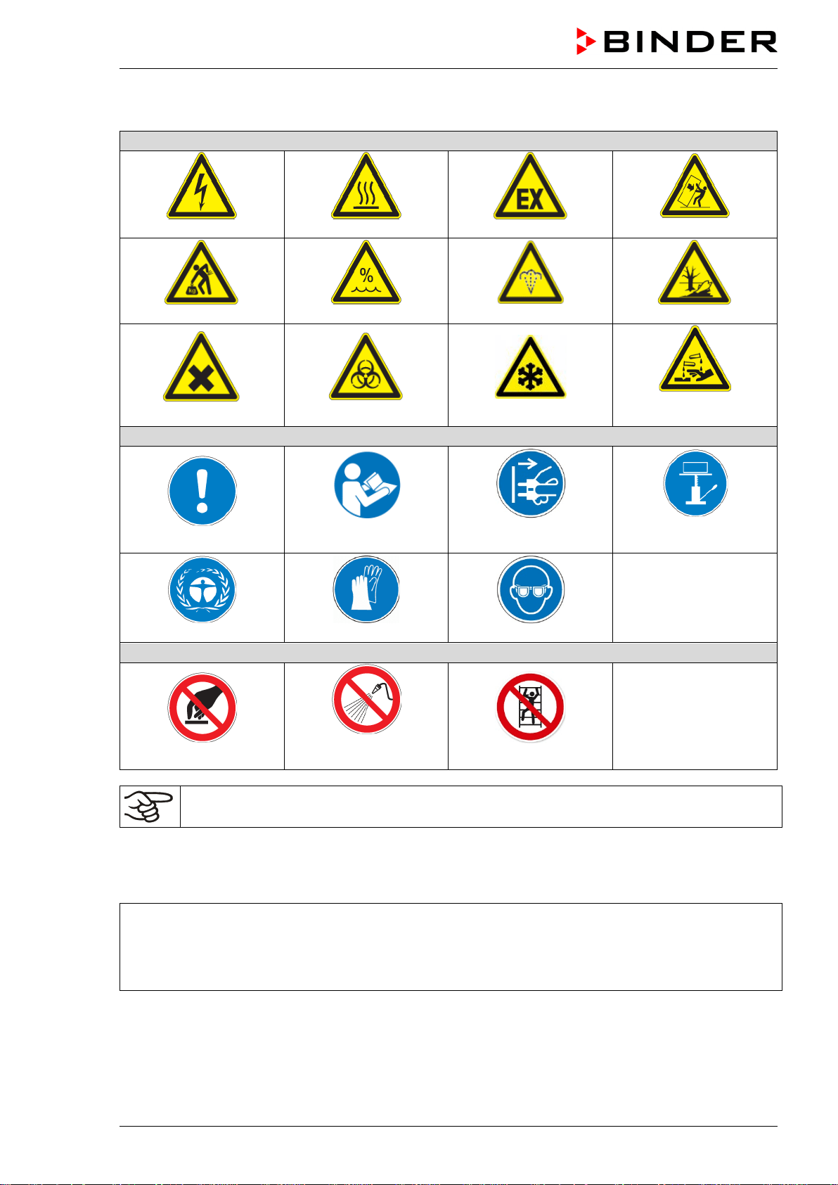
1.4.3 Pictograms
Warning signs
Electrical hazard
Hot surface
Explosive atmosphere
Stability hazard
Lifting hazard
High humidity
Scalding hazard
Pollution hzard
Harmful substances
Biohazard
Danger of frost
Risk of corrosion and /
or chemical burns
Mandatory action signs
Mandatory regulation
Read operating
instructions
Disconnect the power
plug
Lift with mechanical
assistance
Environment protection
Wear protective gloves
Wear safety goggles
Prohibition signs
Do NOT touch
Do NOT spray with
water
Do NOT climb
Information to be observed in order to ensure optimum function of the product.
1.4.4 Word message panel structure
Type / cause of hazard.
Possible consequences.
∅ Instruction how to avoid the hazard: prohibition
Instruction how to avoid the hazard: mandatory action
Observe all other notes and information not necessarily emphasized in the same way, in order to avoid
disruptions that could result in direct or indirect injury or property damage.
MKF / MKFT (E5) 06/2020 page 10/176
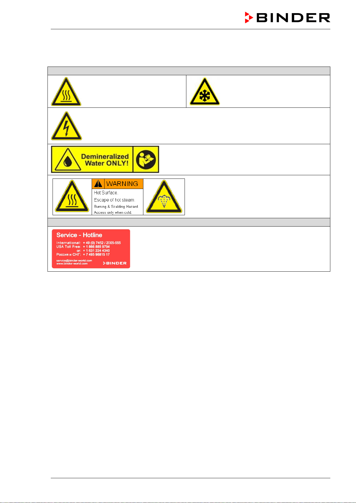
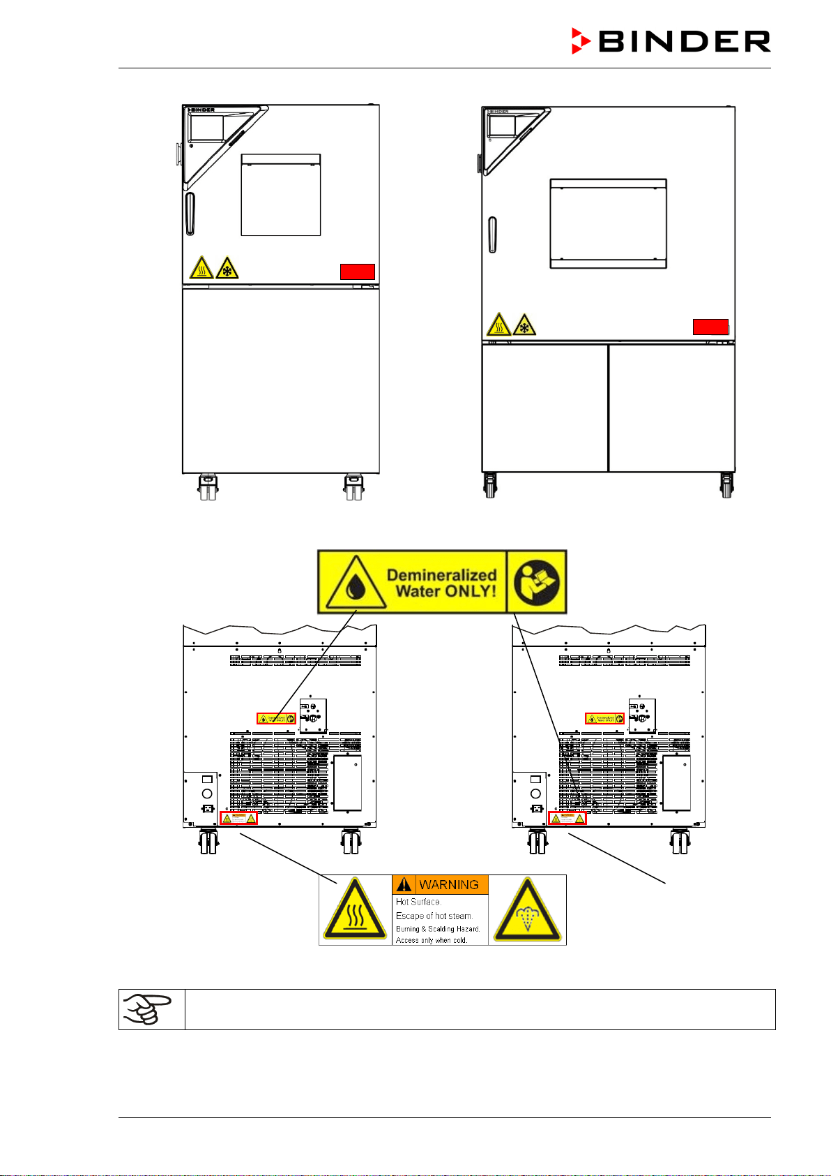
1.5 Localization / position of safety labels on the chamber
The following labels are located on the chamber:
Pictograms (warning signs)
Hot surface (on chamber door)
Cold surface (on chamber door)
Electrical hazard
(chamber with voltage and frequency changer: on the voltage and frequency changer)
Observe the prescribed freshwater quality
(next to water inlet on the rear of the chamber;
on the optional freshwater can)
Burning and scalding hazard (chamber rear)
Service label
MKF / MKFT (E5) 06/2020 page 11/176
Example: MKF 56 Example: MKF 240
Figure 1: Position of labels on the chamber
Keep safety labels complete and legible.
Replace safety labels that are no longer legible. Contact BINDER service for these replacements.
MKF / MKFT (E5) 06/2020 page 12/176
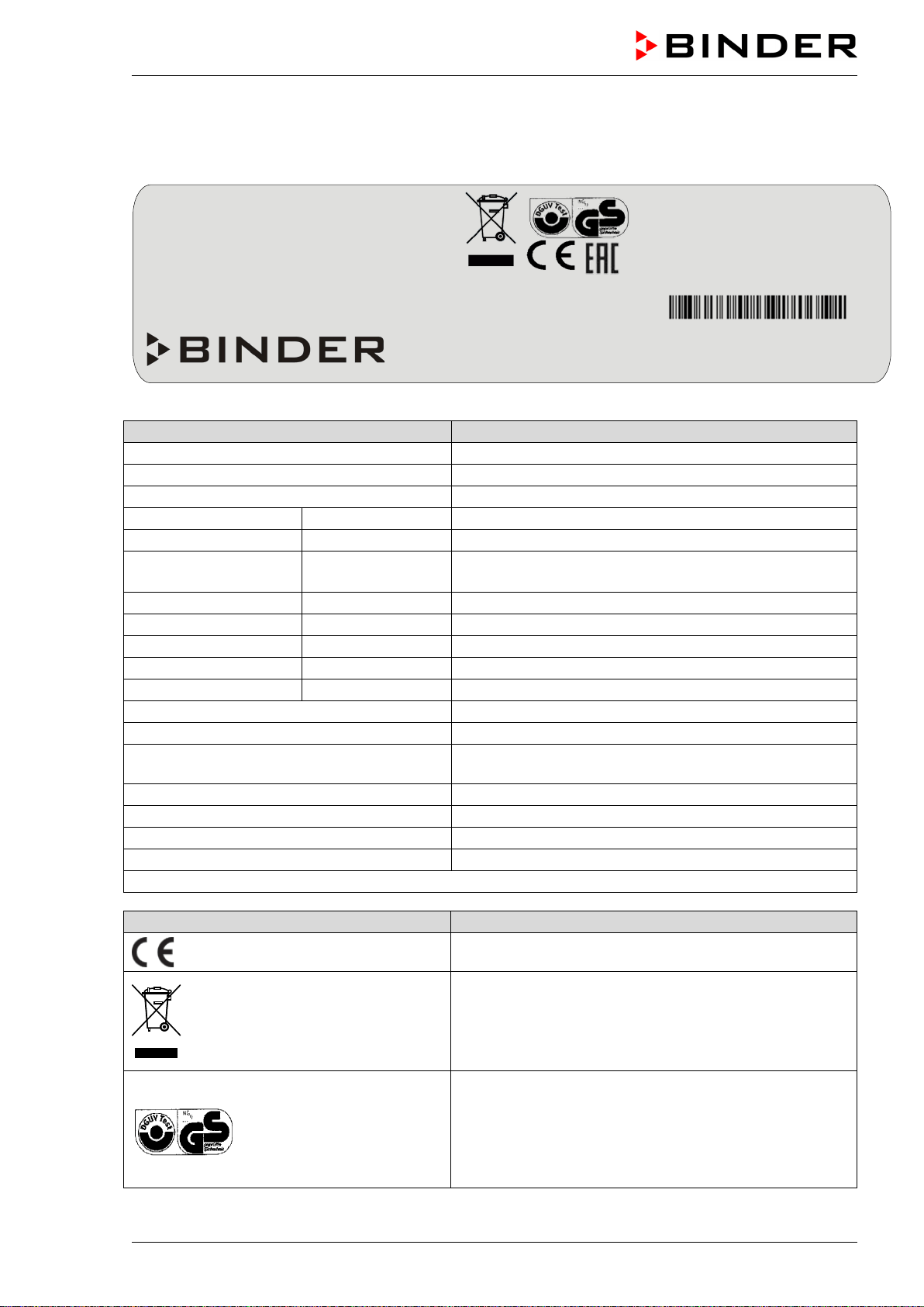
1.6 Type plate
The type plate sticks to the left side of the chamber, bottom right-hand, above the refrigerating and hu-
midity module.
Figure 2: Type plate (example of MKFT 240 regular unit)
Indications of the type plate (example)
Information
BINDER
Manufacturer: BINDER GmbH
MKF 56
Model designation
Alternating climate chamber
Device name
Serial No.
00000000000000
Serial no. of the chamber
Built
2020
Year of construction
Nominal temperature
180 °C
356°F
Nominal temperature
IP protection
20
IP type of protection acc. to standard EN 60529
Temp. safety device
DIN 12880
Temperature safety device acc. to standard DIN 12880
Class
2.0
Class of temperature safety device
Art. No.
9020-0383
Art. no. of the chamber
Project No.
---
Optional: Special application acc. to project no.
6,50 kW
Nominal power
12,0 A
Nominal current
400 V / 50 Hz
Nominal voltage +/- 10% at the indicated power fre-
quency
3 N ~
Current type
Max operating pressure 29 bar
Max operating pressure in the refrigerating system
Stage 1: R 452A - 2,20 kg
Cooling 1
st
stage: Refrigerant type, filling weight
Stage 2: R 23 – 0,40 kg
Cooling 2
nd
stage: Refrigerant type, filling weight
Contains fluorinated greenhouse gases covered by the Kyoto Protocol
Symbol on the type plate
Information
CE conformity marking
Electrical and electronic equipment manufactured /
placed on the market in the EU after 13 August 2005
and be disposed of in separate collection according to
the Directive 2012/19/EU on waste electrical and elec-
tronic equipment (WEEE).
GS mark of conformity of the “Deutsche Gesetzliche
Unfallversicherung e.V. (DGUV), Prüf- und Zertifizier-
ungsstelle Nahrungsmittel und Verpackung im DGUV
Test” (German Social Accident Insurance (DGUV), Test-
ing and Certification Body for Foodstuffs and Packaging
Industry in DGUV Test). (Not valid for MKF056-240V)
Nominal temp.
180 °C
6,50 kW / 12,0 A
Max. operating pressure 29 bar
356 °F
400 V / 50 Hz
Stage 1: R 452A – 2,20 kg
IP protection
20
Stage 2: R 23 - 0,40 kg
Safety device
DIN 12880
3 N ~
Contains fluorinated greenhouse gases
Class
2.0
covered by the Kyoto Protocol
Art. No.
9020-0383
Project No.
Built
2020
Alternating climate chamber
BINDER GmbH
Im Mittleren Ösch 5
78532 Tuttlingen / Germany
www.binder-world.com
MKFT 240
E5
Serial No. 00000000000000
Made in Germany
MKF / MKFT (E5) 06/2020 page 13/176
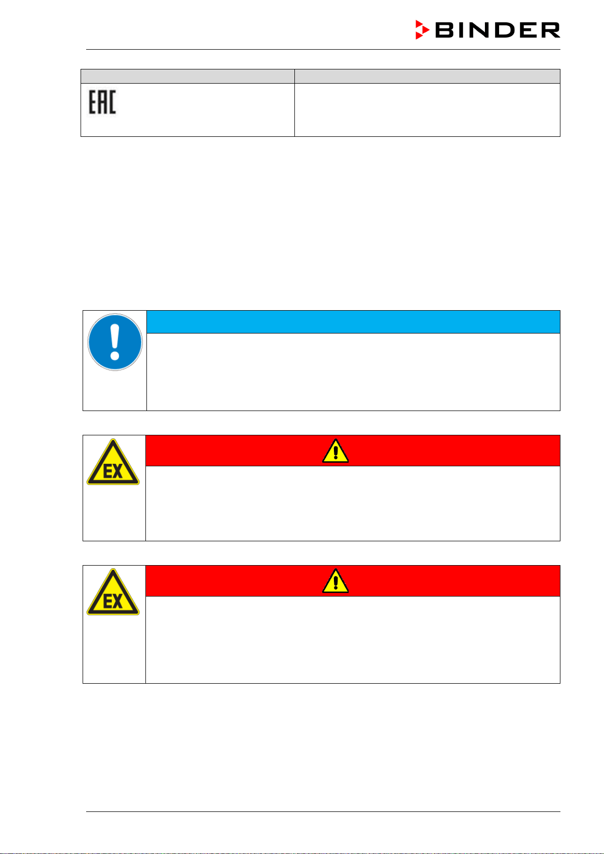
Symbol on the type plate
Information
The chamber is certified according to Customs Union
Technical Regulation (CU TR) for the Eurasian Econom-
ic Union (Russia, Belarus, Armenia, Kazakhstan Kyrgyz-
stan).
1.7 General safety instructions on installing and operating the chamber
With regard to operating the chambers and to the installation location, please observe the local and na-
tional regulations relevant for your country (for Germany: DGUV guidelines 213-850 on safe working in
laboratories, issued by the employers’ liability insurance association).
BINDER GmbH is only responsible for the safety features of the chamber provided skilled electricians or
qualified personnel authorized by BINDER perform all maintenance and repair, and if components relat-
ing to chamber safety are replaced in the event of failure with original spare parts.
To operate the chamber, use only original BINDER accessories or accessories from third-party suppliers
authorized by BINDER. The user is responsible for any risk caused by using unauthorized accessories.
NOTICE
Danger of overheating due to lack of ventilation.
Damage to the chamber.
∅ Do NOT install the chamber in unventilated recesses.
Ensure sufficient ventilation for dispersal of the heat.
Observe the prescribed minimum distances when installing the chamber (chap. 3.4)
Do not install or operate the chamber in hazardous locations.
DANGER
Danger of explosion due to combustible dusts or explosive mixtures in the vicinity
of the chamber.
Serious injury or death from burns and / or explosion pressure.
∅ Do NOT operate the chamber in potentially explosive areas.
KEEP combustible dust or air-solvent mixtures AWAY from the chamber.
The chamber does not dispose of any measures of explosion protection.
DANGER
Danger of explosion due to introduction of flammable or explosive substances in
the chamber.
Serious injury or death from burns and / or explosion pressure.
∅ Do NOT introduce any substance into the chamber which is combustible or explosive at
working temperature.
∅ Do NOT introduce any combustible dust or air-solvent mixture in the inner chamber.
Any solvent contained in the charging material must not be explosive or inflammable. I.e., irrespective of
the solvent concentration in the steam room, NO explosive mixture with air must form. The temperature
inside the chamber must lie below the flash point or below the sublimation point of the charging material.
Familiarize yourself with the physical and chemical properties of the charging material, as well as the
contained moisture constituent and its behavior with the addition of heat energy and humidity.
MKF / MKFT (E5) 06/2020 page 14/176
Familiarize yourself with any potential health risks caused by the charging material, a possibly contained
moisture constituent or by reaction products that may arise during the conditioning process. Take ade-
quate measures to exclude such risks prior to putting the chamber into operation.
DANGER
Electrical hazard by water entering the chamber.
Deadly electric shock.
∅ The chamber must NOT become wet during operation, cleaning, or maintenance.
∅ Do NOT install the chamber in damp areas or in puddles.
Set up the chamber in a splash-proof manner.
The chambers were produced in accordance with VDE regulations and were routinely tested in accord-
ance to VDE 0411-1 (IEC 61010-1).
During and shortly after operation, the temperature of the inner surfaces almost equals the set-point. The
window, the access ports and the inner chamber will become hot during operation.
CAUTION
Danger of burning by touching hot chamber parts during operation.
Burns.
∅ Do NOT touch the inner surfaces, the front panel around the inner chamber, the win-
dow, the access port area or the charging material during operation.
WARNING
Danger of injury and damages by the chamber tipping over or breakaway of the pro-
truding lower housing cover.
Injuries and damage to the chamber and the loading material
∅ Do NOT load the lower housing cover with heavy objects while the chamber door is
open and do NOT climb on it.
1.8 Intended use
Following the instructions in this operating manual and conducting regular maintenance work
(chap. 21.10) is part of the intended use.
Any use of the chambers that does not comply with the requirements specified in this Operating
Manual shall be considered improper use.
Other applications than those described in this chapter are not approved.
Use
Alternating climate chambers series MKF / MKFT are suitable for temperature drying and heat treatment
of solid or pulverized charging material, as well as bulk material, using the supply of heat. The chambers
are specially designed for solving all the problems which occur during material and ageing tests. They are
suitable for harmless materials.
Requirements for the chamber load
Any solvent must not be explosive and flammable. A mixture of any component of the charging material
with air must NOT be explosive. The operating temperature must lie below the flash point or below the
sublimation point of the charging material. Any component of the charging material must NOT be able to
release toxic gases.
MKF / MKFT (E5) 06/2020 page 15/176
The loading material shall not contain any corrosive ingredients that may damage the machine compo-
nents made of stainless steel, aluminum, and copper. Such ingredients include in particular acids and
halides. Any corrosive damage caused by such ingredients is excluded from liability by BINDER GmbH.
The chamber does not dispose of any measures of explosion protection.
DANGER
Explosion or implosion hazard and danger of poisoning through the introduction of
unsuitable loading material.
Poisoning. Serious injury or death from burns and / or explosion pressure.
∅ Do NOT introduce any substance combustible or explosive at working temperature into
the chamber, in particular no energy sources such as batteries or lithium-ion batteries.
∅ NO explosive dust or air-solvent mixture in the inner chamber.
∅ Do NOT introduce any substance which could lead to release of toxic gases.
Contamination of the chamber by toxic, infectious or radioactive substances must be prevented
WARNING
Danger of intoxication and infection through contamination of the chamber with
toxic, infectious or radioactive substances.
Damages to health.
Protect the interior of the chamber from contamination by toxic, infectious or radioactive
substances.
Take suitable protective measures when introducing and removing toxic, infectious or
radioactive material
In case of foreseeable use of the chamber there is no risk for the user through the integration of the
chamber into systems or by special environmental or operating conditions in the sense of EN 61010-
1:2010. For this, the intended use of the chamber and all its connections must be observed.
Medical devices
The chambers are not classified as medical devices as defined by the Medical Device Directive
93/42/EEC.
Due to the special demands of the Medical Device Directive (MDD), these chambers are not
qualified for sterilization of medical devices as defined by the directive 93/42/EWG.
Personnel Requirements
Only trained personnel with knowledge of the Operating Manual can set up and install the chamber, start
it up, operate, clean, and take it out of operation. Service and repairs call for further technical require-
ments (e.g. electrical know-how), as well as knowledge of the service manual.
Installation site requirements
The chambers are designed for setting up inside a building (indoor use).
The requirements described in the Operating Manual for installation site and ambient conditions (Chap.
3.4) must be met.

MKF / MKFT (E5) 06/2020 page 16/176
1.9 Foreseeable Misuse
Other applications than those described in chap. 1.8 are not approved.
This expressly includes the following misuses (the list is not exhaustive), which pose risks despite the
inherently safe construction and existing technical safety equipment:
• Non-observance of Operating Manual
• Non-observance of information and warnings on the chamber (e.g. control unit messages, safety iden-
tifiers, warning signals)
• Installation, startup, operation, maintenance and repair by untrained, insufficiently qualified, or unau-
thorized personnel
• Missed or delayed maintenance and testing
• Non-observance of traces of wear and tear
• Insertion of materials excluded or not permitted by this Operating Manual.
• Non-compliance with the admissible parameters for processing the respective material.
• Installation, testing, service or repair in the presence of solvents
• Installation of replacement parts and use of accessories and operating resources not specified and
authorized by the manufacturer
• Installation, startup, operation, maintenance or repair of the chamber in absence of operating instruc-
tions
• Bypassing or changing protective systems, operation of the chamber without the designated protective
systems
• Non-observance of messages regarding cleaning and disinfection of the chamber.
• Spilling water or cleaning agent on the chamber, water penetrating into the chamber during operation,
cleaning or maintenance.
• Cleaning activity while the chamber is turned on.
• Operation of the chamber with a damaged housing or damaged power cord
• Continued operation of the chamber during an obvious malfunction
• Insertion of objects, particularly metallic objects, in louvers or other openings or slots on the chamber
• Human error (e.g. insufficient experience, qualification, stress, exhaustion, laziness)
To prevent these and other risks from incorrect operation, the operator shall issue operating instructions.
Standard operating procedures (SOPs) are recommended.

MKF / MKFT (E5) 06/2020 page 17/176
1.10 Residual Risks
The unavoidable design features of a chamber, as well as its proper field of application, can also pose
risks, even during correct operation. These residual risks include hazards which, despite the inherently
safe design, existing technical protective equipment, safety precautions and supplementary protective
measures, cannot be ruled out.
Messages on the chamber and in the Operating Manual warn of residual risks. The consequences of
these residual risks and the measures required to prevent them are listed in the Operating Manual. More-
over, the operator must take measures to minimize hazards from unavoidable residual risks. This in-
cludes, in particular, issuing operating instructions.
The following list summarizes the hazards against which this Operating Manual and the Service Manual
warn, and specifies protective measures at the appropriate spots:
Unpacking, Transport, Installation
• Sliding or tilting the chamber
• Setup of the chamber in unauthorized areas
• Installation of a damaged chamber
• Installation of a chamber with damaged power cord
• Inappropriate site of installation
• Missing protective conductor connection
Normal operation
• Assembly errors
• Contact with hot surfaces on the housing
• Contact with hot surfaces in the interior and inside of doors
• Emission of non-ionizing radiation from electrical operating resources
• Contact with live parts in normal state
Cleaning and Decontamination
• Penetration of water into the chamber
• Inappropriate cleaning and decontamination agents
• Enclosure of persons in the interior
Malfunction and Damage
• Continued operation of the chamber during an obvious malfunction or outage of the heating, cooling or
humidification system
• Contact with live parts during error status
• Operation of a unit with damaged power cord
Maintenance
• Maintenance work on live parts.
• Execution of maintenance work by untrained/insufficiently qualified personnel
• Electrical safety analysis during annual maintenance not performed
Trouble-shooting and Repairs
• Non-observance of warning messages in the Service Manual
• Trouble-shooting of live parts without specified safety measures
• Absence of a plausibility check to rule out erroneous inscription of electrical components
MKF / MKFT (E5) 06/2020 page 18/176
• Performance of repair work by untrained/insufficiently qualified personnel
• Inappropriate repairs which do not meet the quality standard specified by BINDER
• Use of replacement parts other than BINDER original replacement parts
• Electrical safety analysis not performed after repairs
1.11 Operating instructions
Depending on the application and location of the chamber, the operator of the chamber must provide the
relevant information for safe operation of the chamber in a set of operating instructions.
Keep these operating instructions with the chamber at all times in a place where they are
clearly visible. They must be comprehensible and written in the language of the employees.
1.12 Measures to prevent accidents
The operator of the chamber must observe the following rule: “Betreiben von Arbeitsmitteln. Betreiben
von Kälteanlagen, Wärmepumpen und Kühleinrichtungen“ (Operation of work equipment. Operation of
refrigeration systems, heat pumps and refrigeration equipment) (GUV-R 500 chap. 2.35) (for Germany).
The manufacturer took the following measures to prevent ignition and explosions:
• Indications on the type plate
See operating manual chap. 1.6.
• Operating manual
An operating manual is available for each chamber.
• Overtemperature monitoring
The chamber is equipped with a temperature display, which can be read from outside.
The chamber is equipped with an additional safety controller (temperature safety device class 2 acc.
to DIN 12880:2007). Visual and audible (buzzer) signals indicate temperature exceeding.
• Safety, measurement, and control equipment
The safety, measuring, and control equipment is easily accessible.
• Electrostatic charge
The interior parts are grounded.
• Non-ionizing radiation
Non-ionizing radiation is not intentionally produced, but released only for technical reasons by electri-
cal equipment (e.g. electric motors, power cables, solenoids). The machine has no permanent mag-
nets. If persons with active implants (e.g. pacemakers, defibrillators) keep a safe distance (distance of
field source to implant) of 30 cm, an influence of these implants can be excluded with high probability.
• Protection against touchable surfaces
Tested according to EN ISO 13732-1:2008.
• Floors
See operating manual chap. 3.4 for correct installation
• Cleaning
See operating manual chap. 22.
MKF / MKFT (E5) 06/2020 page 19/176
• Examinations
The chamber has been inspected by the “Deutsche Gesetzliche Unfallversicherung e.V. (DGUV)
(German Social Accident Insurance (DGUV)” (German Social Accident Insurance (DGUV), Testing
and Certification Body for Foodstuffs and Packaging Industry in DGUV Test) and bears the GS mark.
(Not valid for MKF056-240V)
1.13 Resistance of the humidity sensor against harmful substances
The following list of harmful substances refers only to the humidity sensor and does not include any other
materials incorporated in the chamber or prohibited substances in relation to explosion protection.
Some gases - especially clean gases - do not have any influence on the humidity sensor. Others do have
a very small influence, whereas others may influence the sensor to a larger extent.
• The following gases do not influence the sensor and the humidity measurement: Argon (Ar), carbon
dioxide (CO
2
), helium (He), hydrogen (H
2
), neon (Ne), nitrogen (N
2
), nitrous oxide (N
2
O), oxygen (O
2
)
• The following gases do not, or to a minor extent influence the sensor and the humidity measurement:
Butane (C
4
H
10
), ethane (C
2
H
6
), methane (CH
4
), natural gas propane (C
3
H
8
)
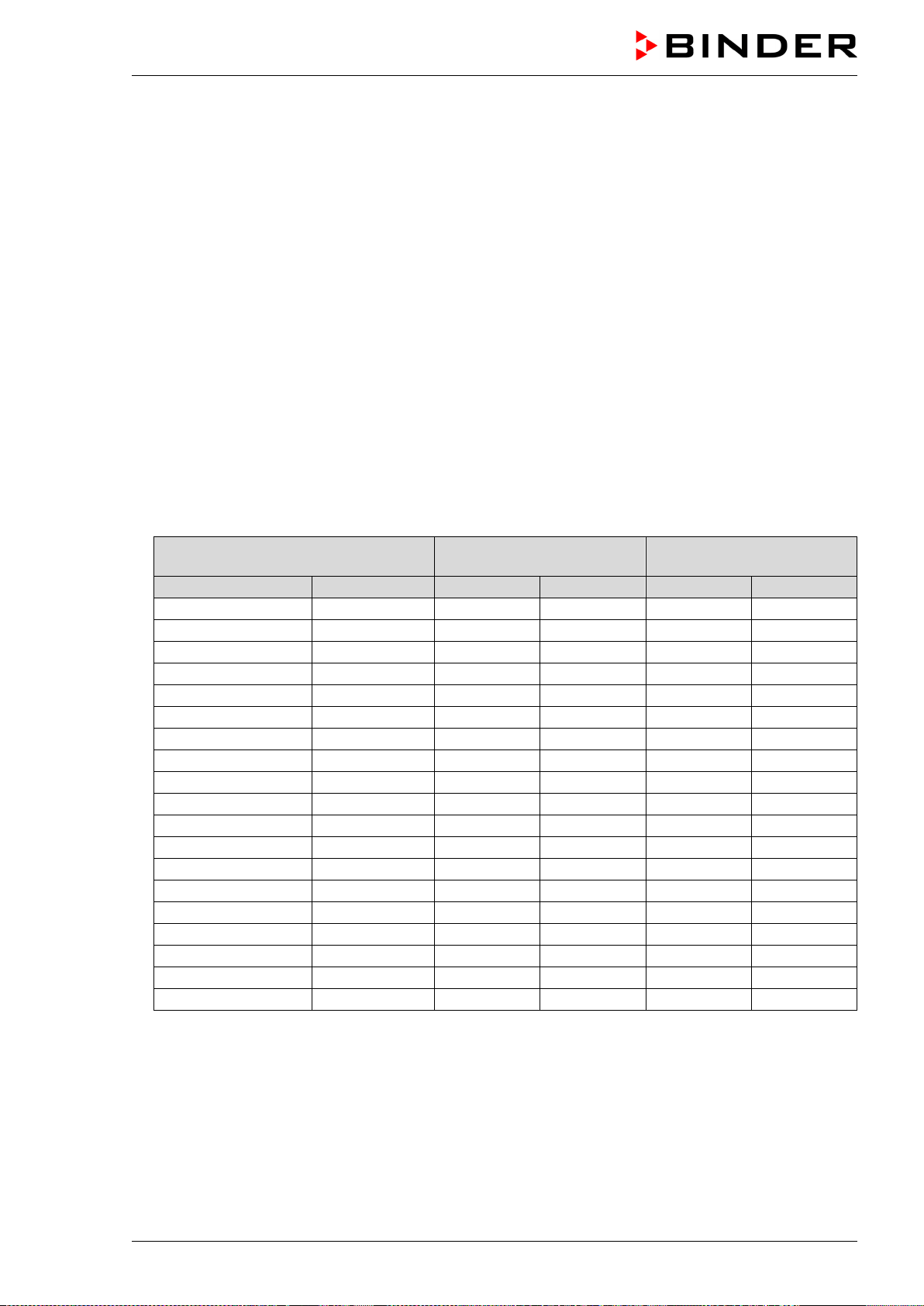
• The following gases do not, or to a minor extent influence the sensor and the humidity measurement,
provided that the indicated loads are not exceeded:
Maximum work place
threshold limit value
Tolerated concentration
with permanent load
Substance
Formula
ppm
mg/m
3
ppm
mg/m
3
Ammonia
NH
3
20
14
5500
4000
Acetone
CH
3
COCH
3
500
1200
3300
8000
Benzene
300
1200
150000
Chlorine
Cl
2
0.5
1.5
0.7
2
Acetic acid
CH
3
COOH
10
25
800
2000
Ethyl acetate
CH
3
COOC
2
H
5
400
1400
4000
15000
Ethanol
C
2
H
5
OH
500
960
3500
6000
Ethylene glycol
HOCH
2
CH
2
OH
10
26
1200
3000
Formaldehyde
HCHO
0.3
0.37
2400
3000
Isopropanol
(CH
3
)
2
CHOH
200
500
4800
12000
Methanol
CH
3
OH
200
260
3500
6000
Methyl ethyl ketone
C
2
H
5
COCH
3
200
590
3300
8000
Ozone
O
3
0.1
0.2
0.5
1
Hydrochloric acid
HCl
2
3
300
500
Hydrogen sulphide
H
2
S
10
15
350
500
Nitrogen oxides
NO
x
5
9
5
9
Sulphur dioxide
SO
2
5
13
5
13
Toluol
C
6
H
5
CH
3
100
380
1300
5000
Xylene
C
6
H
4
(CH
3
)
2
100
440
1300
5000
These values are to be considered only as approximate values. The sensor resistance largely de-
pends on the temperature and humidity conditions during the time of exposure to harmful substances.
Avoid simultaneous condensation. Tolerated error of measurement: ± 2 % r.h. The maximum work
place threshold limit value is the one that can be regarded as harmless for humans.
• Vapors of oil and fat are dangerous for the sensor because they may condensate at the sensor and
thus prevent its function (insulating layer). For similar reasons it is not possible to measure smoke
gases.

MKF / MKFT (E5) 06/2020 page 20/176
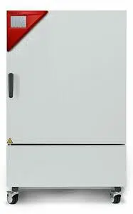
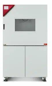
2. Chamber description
The alternating climate chamber MKF / MKFT is a specially developed precision cooling/warming cabinet
for the domain of industrial material testing and environment simulation, with an unrivalled capacity, which
far exceeds the capabilities of normal test cabinets, providing the ideal facilities for solving all the prob-
lems which occur during material as well as ageing and stress tests.
The chambers are equipped with a multifunctional microprocessor display controller with 2-channel tech-
nology for temperature and humidity plus a digital display accurate to one-tenth of a degree resp. 0.1%
r.H. With its comprehensive program control functions, the display program controller MB2 permits the
high precision performance of temperature and humidity cycles with rapid heating up and cooling down
phases.
With its microprocessor controlled humidifying and dehumidifying system the chamber is a high-precision
climatic test chamber. It covers the regular test specifications for temperature and climates corresponding
to DIN und IEC standards. Furthermore, it permits simulating exactly and over long periods constant con-
ditions for other applications such as sample conditioning for material testing of paper, textiles, plastics,
building materials, etc.
The patented APT.line™ preheating chamber and air conduction technology guarantees excellent spatial
temperature and humidity values for the total working area. The chamber provides a powerful refrigerat-
ing system with rapid cooling-down speeds. In addition, the chamber provides almost unlimited possibili-
ties for adaptation to individual customer requirements based upon extensive programming options.
A resistance humidifying system humidifies the air. For this purpose, use deionized (demineralized) wa-
ter. The option BINDER Pure Aqua Service permits using the chamber with any degree of water hard-
ness.
The high-quality housing insulation guarantees both a low noise mode of operation and a consistently low
housing temperature. The inner chamber, the pre-heating chamber and the interior side of the doors are
all made of stainless steel V2A (German material no. 1.4301, US equivalent AISI 304). When operating
the chamber at temperatures above 150 °C / 302°F, the impact of the oxygen in the air may cause discol-
oration of the metallic surfaces (yellowish-brown or blue) by natural oxidation processes. These colora-
tions are harmless and will in no way impair the function or quality of the chamber. The housing is RAL
7035 powder-coated. All corners and edges are completely coated.
The efficient program controller is equipped with a multitude of operating functions, in addition to recorder
and alarm functions. Programming of test cycles is easily accomplished via the modern touchscreen con-
troller MB2 and is also possible directly with a computer via Intranet in connection with the APT-COM™ 4
Multi Management Software (option, chap. 21.1). The chamber comes equipped with an Ethernet serial
interface for computer communication. In addition, the BINDER APT-COM™ 4 Multi Management Soft-
ware (option) permits networking up to 100 chambers and connecting them to a PC for controlling and
programming, as well as recording and representing temperature and humidity data. For further options,
see chap. 25.6.
The chambers are equipped with
four castors. Both front castors can be easily locked via the attached
brakes.
Temperature ranges:
• MKF without humidity: -40 °C / 104 °F up to +180 ºC / 356 °F,
• MKFT without humidity: -70 °C / -94 °F up to +180 ºC / 356 °F,
• MKF / MKFT in climatic operation: + 10 °C / 50 °F up to +95 °C / 203 °F
• Chambers with optional compressed air dryer in climatic operation: 0 °C / 32 °F up to +95 °C / 203 °F
Humidity ranges:
• 10% up to 98% r.h.
• Chambers with optional compressed air dryer: 5 % r.h. up to 98 % r.h.
MKF / MKFT (E5) 06/2020 page 21/176
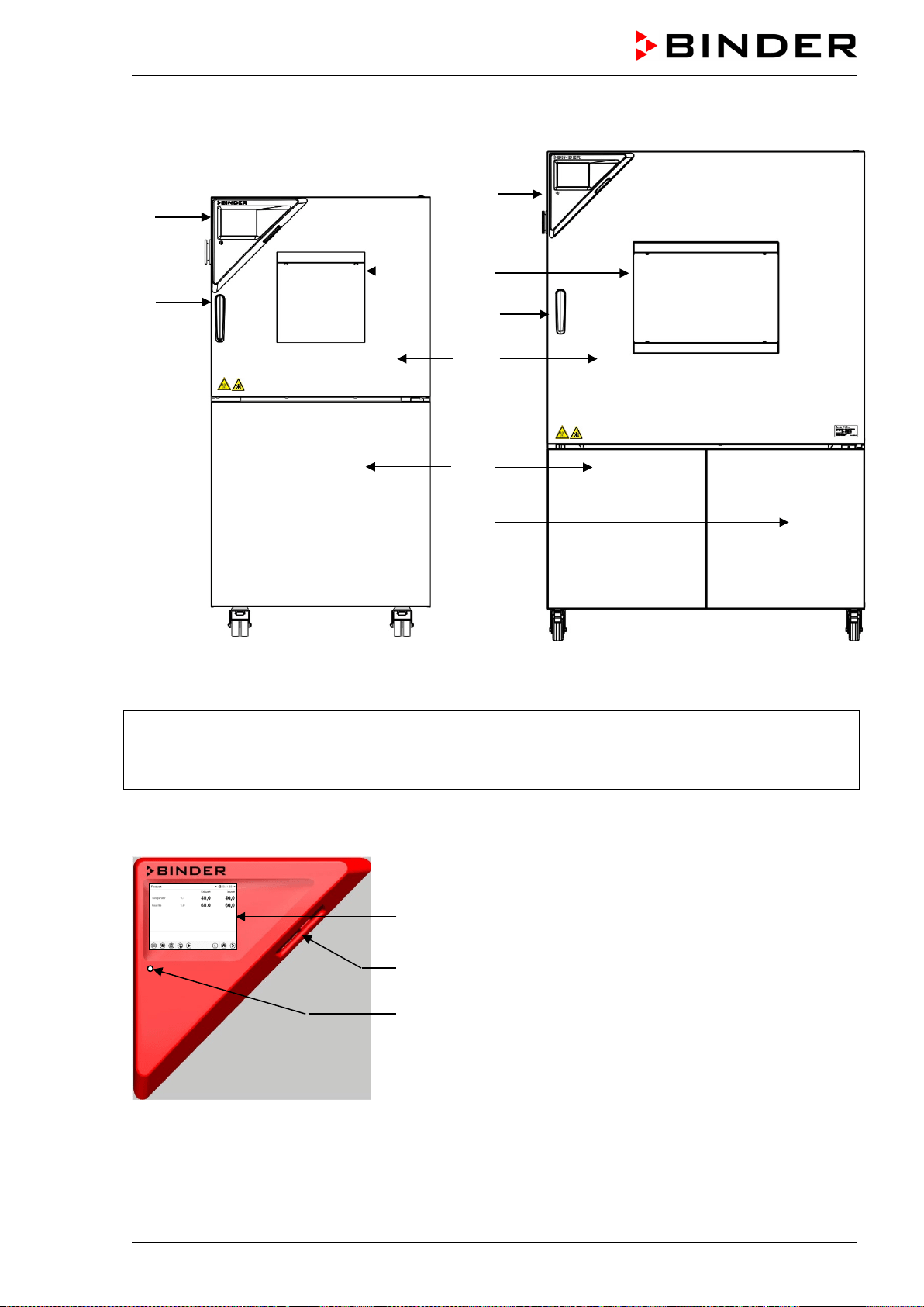
2.1 Chamber overview
MKF 56 MKF 240
Figure 3: Alternating climate chambers MKF / MKFT
(A) Instrument panel
(B) Door handle
(C) Window
(D) Door
(E) Refrigeration / humidity module
(F)
Access to fill the water can
2.2 Instrument panel
5,7" controller display with touchscreen
USB interface
Pilot lamp
Figure 4: Instrument panel with MB2 program controller and USB interface
(A)
(C)
(B)
(D)
(E)
(F)
(A)
(B)
MKF / MKFT (E5) 06/2020 page 22/176
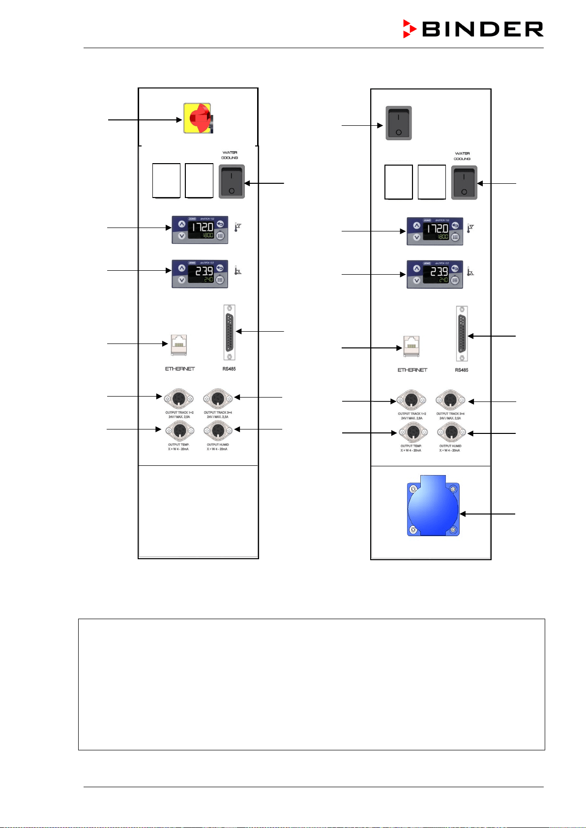
2.3 Lateral control panel
(1)
(4a)
(4b)
(5)
(7)
(9)
(3)
(5a)
(8)
(10)
(1)
(4a)
(4b)
(5)
(7)
(9)
(3)
(5a)
(8)
(10)
(11)
MKF 56 MKF / MKFT 115 / 240 / 720
Figure 5: Lateral control panel at the right side of the humidity module with options
(1) Main power switch ON/OFF
(2) not used
(3) Switch for water cooling (option, not com-
ing with size 720)
(4) Temperature safety device class 2 for
over and under temperature (option):
Entry displays for upper (4a) and lower
(4b) temperature limit
(5) Ethernet interface for computer commu-
nication
(5a) RS485 interface for computer communication
(option)
(6) not used
(7) 2 zero-voltage relay outputs via operation lines
(8) 2 zero-voltage relay outputs via operation lines
(9) Analog output for temperature (option)
(10) Analog output for humidity (option)
(11)
Socket 230 V AC, max. 500 W (MKF/MKFT 115,
240, 720)
MKF / MKFT (E5) 06/2020 page 23/176
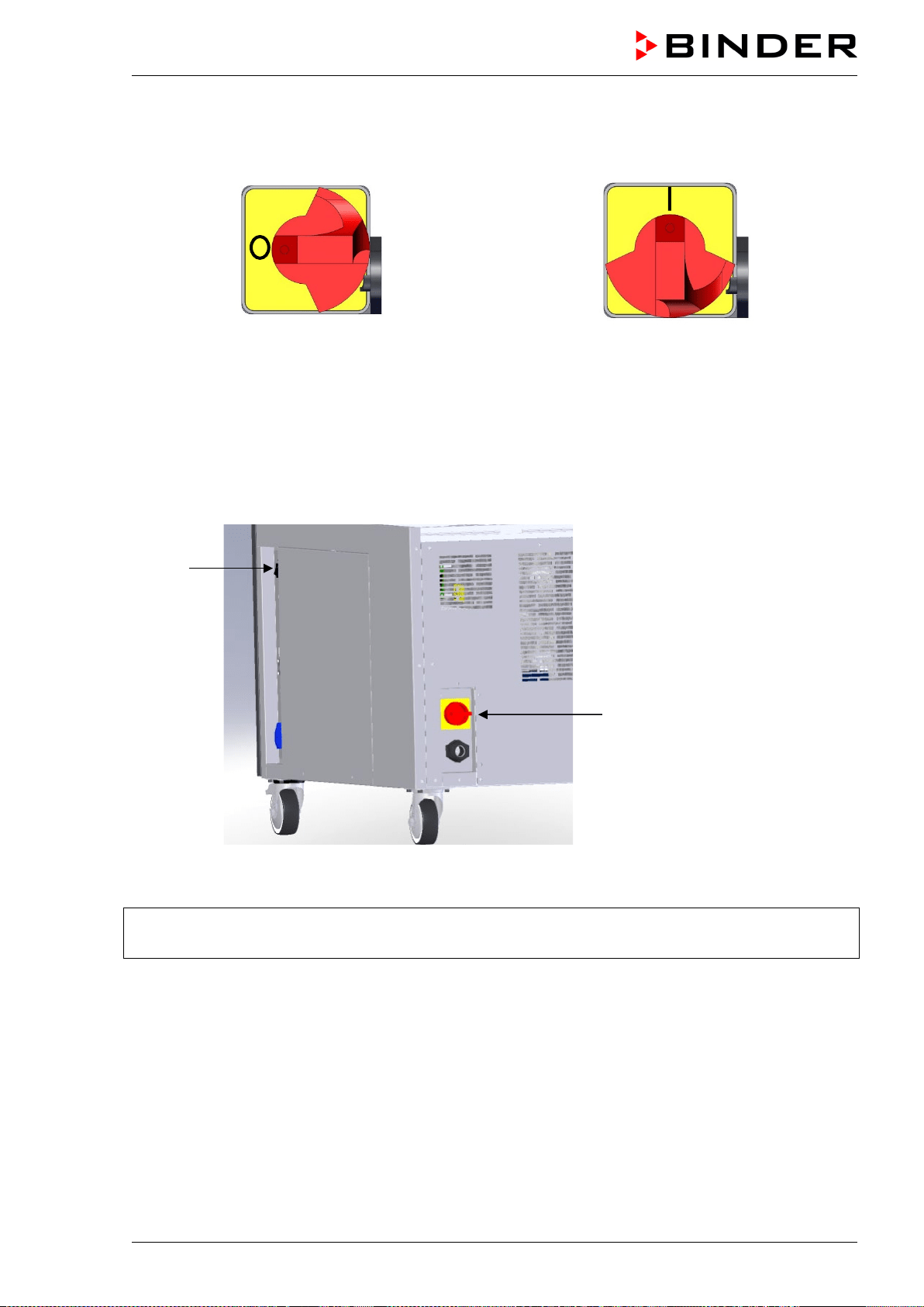
2.4 Main power switch (MKF 56)
This switch allows completely switching off the chamber (de-energized condition).
Off On
Figure 6: Main power switch (1) in the lateral control panel of MKF 56
2.5 Rear power switch (MKF / MKFT 115, 240, 720)
This switch allows completely switching off the chamber (de-energized condition).
(1)
(12)
Figure 7: Rear view MKF/MKFT 115, 240, 720
(1) Main power switch On / Off
(12) Rear power switch
MKF / MKFT (E5) 06/2020 page 24/176
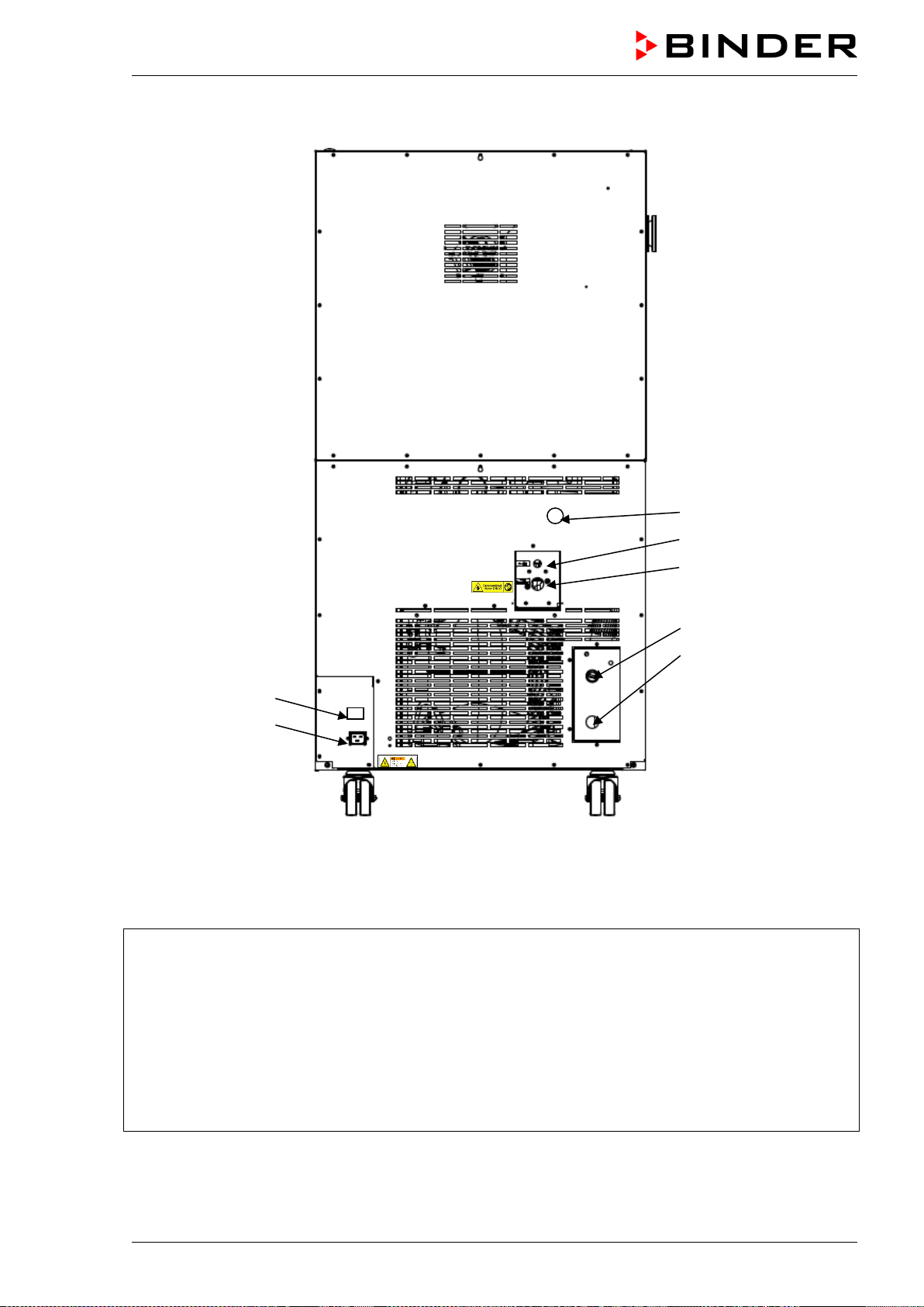
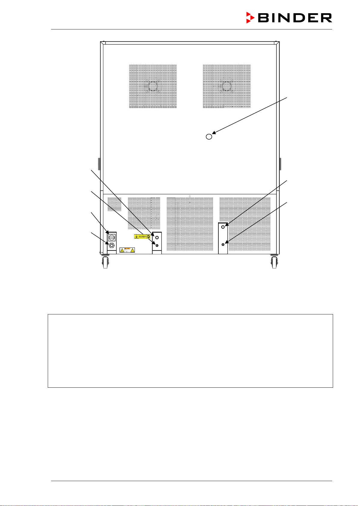
2.6 Rear chamber view
(18)
(19)
(20)
(14)
(15)
(16)
(17)
Figure 8: MKF 56 rear view with water connections
and the options water cooling and compressed air connection
(14) Wastewater connection “OUT” with hose olive
for hose ½“
(15) Freshwater connection “IN” with screw thread
¾’’ for hose ½“, with union nut
(16) Connection “OUT” for cooling water outlet with
screw thread ¾’’ for hose ½“, with union nut
(water cooling option)
(17) Connection “IN” for cooling water inlet with
screw thread ¾’’ for hose ½“, with union nut
(water cooling option)
(18) Socket for optional freshwater can (option
for MKF 56, chap. 21.9)
(19) IEC connector plug
(20) Compressed air connection (option): Cou-
pling connector to connect compressed air
or the compressed air dryer (option)
MKF / MKFT (E5) 06/2020 page 25/176
(15)
(14)
(12)
(19)
(20)
(16)
(17)
Figure 9: MKF/MKFT 115, 240, 720 rear view with water connections
and the options water cooling and compressed air connection (example: MKF 720)
(12) Rear power switch
(13) not used
(14) Wastewater connection “OUT” with hose olive
for hose ½“
(15) Freshwater connection “IN” with screw thread
¾’’ for hose ½“, with union nut
(16) Connection “OUT” for cooling water outlet with
screw thread ¾’’ for hose ½“, with union nut
(water cooling option)
(17) Connection “IN” for cooling water inlet with
screw thread ¾’’ for hose ½“, with union
nut (water cooling option)
(18) not used
(19) Power connection
(20) Compressed air connection (option): Cou-
pling connector to connect compressed air
or the compressed air dryer (option)
MKF / MKFT (E5) 06/2020 page 26/176
3. Completeness of delivery, transportation, storage, and installa-
tion
3.1 Unpacking, and checking equipment and completeness of delivery
After unpacking, please check the chamber and its optional accessories, if any, based on the delivery
receipt for completeness and for transportation damage. Inform the carrier immediately if transportation
damage has occurred.
The final tests of the manufacturer may have caused traces of the shelves on the inner surfaces. This has
no impact on the function and performance of the chamber.
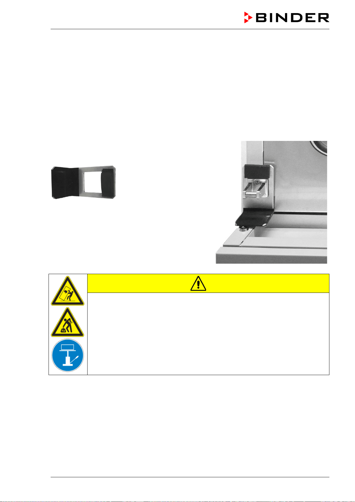
Please remove any transportation protection devices and adhesives in/on the chamber and on the doors
and take out the operating manuals and accessory equipment.
Remove the upholstered transport piece (L-type profile)
from the lower door locking and keep it for possible later
transportation.
Figure 10:
Door locking with transport piece (state of delivery)
CAUTION
Risk of injury and damages by lifting heavy loads and by sliding or tilting of the
chamber due to improper lifting.
Injuries, damage to the chamber.
∅ Do NOT lift or transport the chamber using the door handle, the door or the lower
housing.
∅ Do NOT lift the chamber by hand.
Keep the chamber in upright position.
Lift the chamber from the pallet using technical devices (fork lifter). Set the fork lifter
only from the rear in the middle of the chamber. Make sure to place all the lateral sup-
ports of the chamber on the forks.
If you need to return the chamber, please use the original packing and observe the guidelines for safe
lifting and transportation (chap. 3.2).
For disposal of the transport packing, see chap. 24.1.
Note on second-hand units (Ex-Demo-Units)
Second-hand units are chambers that have been used for a short time for tests or exhibitions. They are
thoroughly tested before resale. BINDER ensures that the chamber is technically sound and will work
flawlessly.
Second-hand units are marked with a sticker on the chamber door. Please remove the sticker before
commissioning the chamber.
MKF / MKFT (E5) 06/2020 page 27/176
3.2 Guidelines for safe lifting and transportation
The front castors of the chamber can be blocked by brakes. Please move the chambers with castors only
when empty and on an even surface, otherwise the castors may be damaged. Mount the upholstered
steel L-type profile at the lower door locking. After operation please observe the guidelines for temporarily
decommissioning the chamber (chap. 24.2).
CAUTION
Risk of injury and damages by lifting heavy loads and by sliding or tilting of the
chamber due to improper transportation.
Injuries, damage to the chamber.
∅ Do NOT lift or transport the chamber using the door handle, the door or at the lower
housing.
∅ Do NOT lift the chamber by hand.
Transport the chamber only in its original packaging.
Secure the chamber with transport straps for transport.
Keep the chamber in upright position.
Place the chamber using technical devices (fork lifter) on the transport pallet. Set the
fork lifter only from the rear in the middle of the chamber. Make sure to place all the
lateral supports of the chamber on the forks.
Transport the chamber with the original transport pallet. Set the fork lifter ONLY to the
pallet. Without the pallet the chamber is in imminent danger of overturning.
You can order transport packing and pallets for transportation purposes from BINDER service.
Permissible ambient temperature range during transport:
• If the steam humidifying system has NOT been emptied: +3 °C / 37.4 °F to +60 °C / 140 °F.
• After BINDER Service has emptied the steam humidifying system: -10 °C / 14 °F to +60 °C / 140 °F.
With temperatures below +3 °C / 37.4 °F, water must be completely removed from the humidifying sys-
tem.
NOTICE
Danger of freezing in the steam generator when transporting the chamber below
+3 °C / 37.4 °F with filled steam humidifying system.
Damage to the chamber.
Contact BINDER Service before any transportation below +3 °C / 37.4 °F.
3.3 Storage
Intermediate storage of the chamber is possible in a closed and dry room. Observe the guidelines for
temporary decommissioning (chap. 24.2).
Permissible ambient temperature range during storage:
• If the steam humidifying system has NOT been emptied: +3 °C / 37.4 °F to +60 °C / 140 °F.
• After BINDER Service has emptied the steam humidifying system: -10 °C / 14 °F to +60 °C / 140 °F.
MKF / MKFT (E5) 06/2020 page 28/176
With temperatures below +3 °C / 37.4 °F, water must be completely removed from the humidifying sys-
tem.
NOTICE
Danger of freezing in the steam generator when storing the chamber below +3 °C /
37.4 °F with filled steam humidifying system.
Damage to the chamber.
Contact BINDER Service before any storage below +3 °C / 37.4 °F.
Permissible ambient humidity: max. 70 % r.h., non-condensing
After extensive operation at humidity levels > 70% r.h., condensation from excessive humidity can lead to
corrosion during storage. In this case the chamber must first be dried.
NOTICE
Danger of corrosion on the housing due to condensation by excess humidity after
operating at humidity values > 70 % r.h. for a long period.
Damage to the chamber.
Let the chamber dry for several days before shut-down:
• Set the humidity to 0 % r.h. To enable dehumidification, the humidifying and dehu-
midifying system must be acti
vated (deactivated operation line “Humidity off”, chap.
7.3 and setting “Control on”, chap. 6.3).
• Set the temperature set point to 60 °C / 140 °F
(Manual mode). Let the chamber
operate for approx. 2 hours with closed door. Remove the access port plugs.
• Only then, shut down the chamber at the
main power switch (1) and close the tap of
the water supply.
After drying the chamber for decommissioning, the humidity value will approximate ambient
humidity.
When after storage in a cold location you transfer the chamber to its warmer installation site, condensa-
tion may form. Before start-up, wait at least two hours until the chamber has attained ambient tempera-
ture and is completely dry and the oil in the compressors has warmed up.
In case of a prolonged temporal decommissioning, leave the chamber door open or remove the access
port plugs.
3.4 Location of installation and ambient conditions
Set up the chamber on a flat, even and non-flammable surface, free from vibration, and in a well-
ventilated, dry location and align it using a spirit level. The site of installation must be capable of support-
ing the chamber’s weight (see technical data, chap. 25.4). The chambers are designed for setting up in-
side a building (indoor use).
When after storage in a cold location you transfer the chamber to its warmer installation site, condensa-
tion may form. Before start-up, wait at least two hours until the chamber has attained ambient tempera-
ture and is completely dry and the oil in the compressors has warmed up.
NOTICE
Danger of overheating due to lack of ventilation.
Damage to the chamber.
∅ Do NOT install the chamber in unventilated recesses.
Ensure sufficient ventilation for dispersal of the heat.
Observe the prescribed minimum distances when installing the chamber.
MKF / MKFT (E5) 06/2020 page 29/176
Do not install or operate the chamber in potentially explosive areas.
DANGER
Danger of explosion due to combustible dusts or explosive mixtures in the vicinity
of the chamber.
Serious injury or death from burns and / or explosion pressure.
∅ Do NOT operate the chamber in potentially explosive areas.
KEEP explosive dust or air-solvent mixtures AWAY from the vicinity of the chamber.
Ambient conditions
• Permissible ambient temperature range during operation: +18 °C / 64.4 °F to +32 °C / 89.6 °F. At ele-
vated ambient temperature values, fluctuations in temperature can occur.
The ambient temperature should not be substantially higher than the indicated ambient
temperature of +22 °C +/- 3 °C to which the specified technical data relate. For other am-
bient conditions, deviations from the indicated data are possible.
• Permissible ambient humidity: 70 % r.h. max., non-condensing.
When operating the chamber at temperature set-points below ambient temperature, high ambient hu-
midity may lead to condensation on the chamber.
• Installation height: max. 2000 m / 6.6 ft. above sea level.
Minimum distances:
• Distance between each chamber when placing several chambers of the same size side by side: 250
mm / 9.84 in
• Lateral wall distance: 200 mm / 7.87 in
• Wall distance rear: 300 mm / 11.81 in
• Chambers with optional water cooling (without options compressed air dryer and / or voltage and fre-
quency changer): Wall distance rear 100 mm / 3.94 in.
• Chambers with optional compressed air dryer: Wall distance rear approx. 1 m / 3.28 ft so that it is pos-
sible to read the status display of the compressed air dryer on the chamber rear.
• Chambers with voltage and frequency changer: rear wall distance of the alternating climate chamber
approx. 1 m / 3.28 ft to set up the voltage and frequency changer
• To completely separate the chamber from the power supply, you must disconnect the power plug. In-
stall the chamber in a way that the power plug is easily accessible and can be easily pulled in case of
danger.
• Spacing above the chamber: 100 mm / 3.94 in
NOTICE
Danger by stacking.
Damage to the chambers.
∅ Do NOT place the chambers on top of each other.
Other requirements
A water tap (1 bar to 10 bar) is necessary for the installation of the humidification system. If no suitable
house water connection is available, you can manually supply water by filling the water can (MKF 56:
optional external water can, chap. 4.2.2, 21.9, MKF/MKFT 115, 240, 720: internal water can chap. 4.2.3).
To avoid any possible water damage, provide a floor drain at the location of the device. Select
a suitable installation site to avoid any consequential damage by splashing water.
MKF / MKFT (E5) 06/2020 page 30/176
To completely separate the chamber from the power supply, you must disconnect the power plug. Install
the chamber in a way that the power plug is easily accessible and can be easily pulled in case of danger.
With an increased amount of dust in the ambient air, clean the condenser fan several times a year. We
recommend checking the fan grid (behind the left maintenance access flap) every week. In case of visible
dirt accumulation, disconnect the chamber and clean the fan grid by suction.
Avoid any conductive dust in the ambiance according to the chamber layout complying with pollution de-
gree 2 (IEC 61010-1).
MKF 56: With option “External freshwater and wastewater cans” (chap. 21.9): Install the chamber in a
way that the freshwater can is easily accessible for filling.
4. Installation and connections
4.1 Wastewater connection for humidifying system
Fasten the wastewater hose to the wastewater connection “OUT” (14) on the rear of the chamber (olive ∅
14 mm). Observe the following points:
• You can use a part of the supplied tap water hose as a drainage hose. In case another hose is used, it
has to be permanently resistant against at least 95 °C / 203 °F.
• Mount the wastewater hose with a maximum positive inclination of 1 m and a maximum total length of
3 m.
• Protect both ends of the drainage hose with two of the four supplied hose clamps.
Wastewater is collected in an internal can with a volume of approx. 0.5 liters. It is pumped off
only when required, thus there is no continuous wastewater flow.
Protect the wastewater supply at both sides with the supplied hose clamps.
4.2 Freshwater supply for humidifying system
Connect the wastewater pipe before connecting the chamber to a freshwater pipe or filling the
water can (internal water can: regular with MKF/MKFT 115, 240, 720, external water can: op-
tional for MKF 56).
MKF 56: You can supply the chamber with freshwater via a water pipe or by manually filling an external
water can (option chap. 21.9).
MKF/MKFT 115, 240, 720: You can supply the chamber with freshwater via a water pipe or by manually
filling the internal water can. It is not necessary to switch between both possibilities. When connecting to
a water pipe, the water can is automatically filled.
Water intake temperature NOT below +5 °C / 41 °F and not exceeding 40 °C / 104 °F.
NOTICE
Danger of calcification of the humidifying system.
Damage to the chamber.
Operate the chamber with deionized (demineralized) water only.
MKF / MKFT (E5) 06/2020 page 31/176
Types of suitable water quality
• Deionized water from a water treatment installation already existing at the customer's site. Conductivi-
ty from 1 µS /cm up to a maximum of 20 µS/cm. (Water, which is in equilibrium with the CO
2
in the air,
and has a conductivity below 1 µS/cm (ultrapure water), may cause acid corrosion due to its low pH.)
• Tap water treated by the optional water treatment system BINDER Pure Aqua Service (disposable
system). A reusable measuring equipment to assess the water quality is included (chap. 21.10).
BINDER GmbH is NOT responsible for the water quality at the user’s site.
Any problems and malfunctions that might arise following use of water of deviating quality is
excluded from liability by BINDER GmbH.
The warranty becomes void in the event of use of water of deviating quality.
4.2.1 Automatic fresh water supply for humidifying system via water pipe
An enclosure inside the chamber contains the connection kit for water supply and wastewater. Install the
water supply connection using either the enclosed water hose or another pressure-resistant one. To ac-
complish this, remove the cover of the freshwater connection “IN” (15) on the rear of the chamber. Protect
both ends of the hose with two of the four supplied hose clamps. Before turning on the chamber, check
the connection for leaks. Water supply is automatically effected via the freshwater connection “IN” (15).
As the chamber only lets in water when required, there is no continuous water flow.
• Supply pressure 1 to 10 bar when connecting to a water pipe.
• Water type: deionized (demineralized) water
• Water intake temperature NOT below +5 °C / 41 °F and not exceeding 40 °C / 104 °F.
• The water intake shall be provided with a shut-off slide or water-tap.
•
For the water supply, fix the delivered adapter with hose olive on the thread at the rear of
the chamber.
• Protect the water supply at one side with the supplied hose clamp.
4.2.2 Manual fresh water supply via external freshwater can (option for MKF 56)
If no house water connection with suitable water is available, you can manually supply water by filling a
freshwater can (option, volume: 20 liters / 0.71 cu.ft. You can place the freshwater can next to the cham-
ber (chap. 21.9).
To guarantee humidification during 24 hours even at high humidity set-points with manual
water supply, we recommend filling the freshwater can (option) daily at the end of the day.
4.2.3 Manual fresh water supply for humidifying system via internal freshwater can
(MKF/MKFT 115, 240, 720)
If no house water connection with suitable water is available, you can manually supply water by filling the
freshwater can (total volume: 19 liters / 0.67 cu.ft. up to the maximum level mark), which is located behind
the right door of the humidity generation module.
The cover of the water inlet valve must be screwed on the freshwater connection “IN” (15). Open the door
(F) to access the filler neck of one of the water can. You cannot totally take out the water can because of
its fix connections. Fill the water can only up to ¾, up to the maximum level mark. When filling it too much
with the chamber turned on, the alarm message “Freshwater can overflow” is displayed on the controller
(chap. 11.1.3). Manually suck off the water, or operate the chamber with high temperature and humidity
values until the excess water is consumed. When filling it too much with the chamber turned off, water
can escape from the chamber. Thus, ensure not to fill the can by more than the maximum level mark.
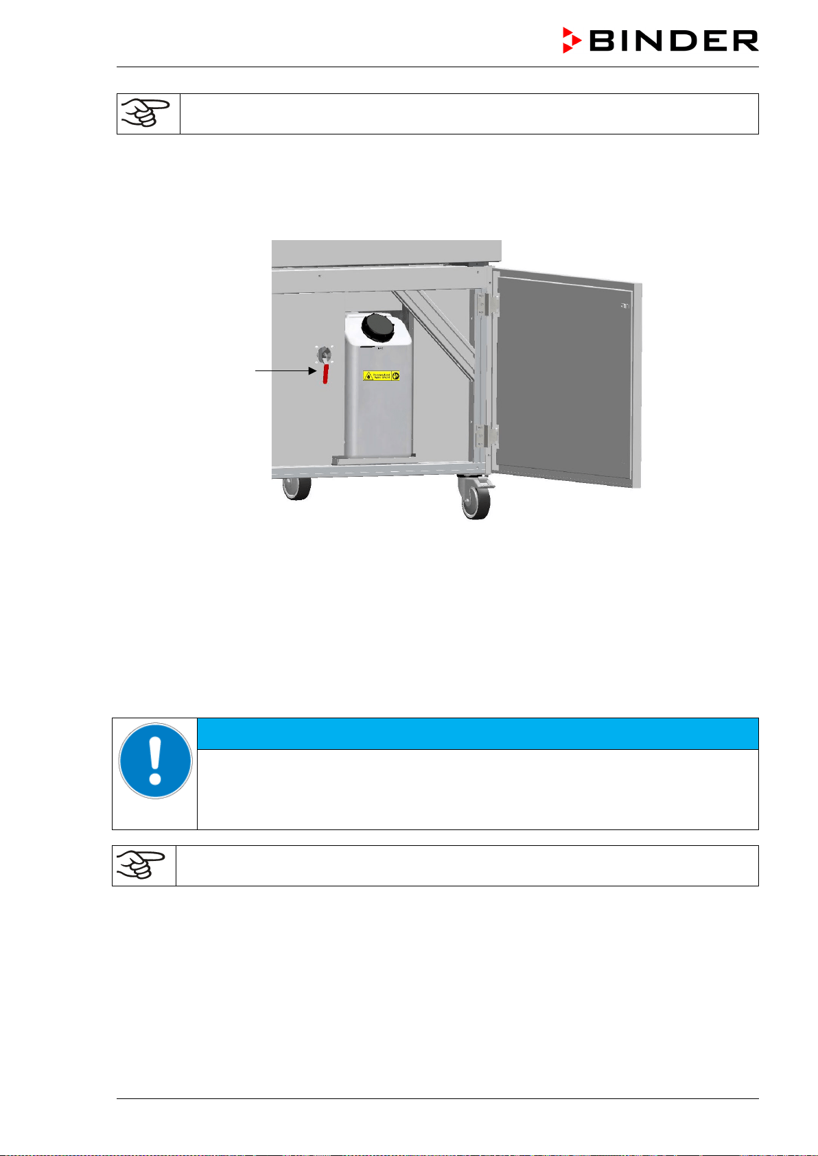
MKF / MKFT (E5) 06/2020 page 32/176
To guarantee humidification during 24 hours even at high humidity set-points with manual
water supply, we recommend filling the freshwater can daily at the end of the day.
4.2.4 Water circle: lever for condensate recycling (option for MKF/MKFT 115, 240, 720)
Figure 11: Lever for condensate recycling (open position)
next to the freshwater can behind the maintenance access door
The lever (25) for condensate recycling is located behind the maintenance access door next to the fresh-
water can.
• Open lever (vertical position): the condensate from the interior is conducted to the freshwater can. Use
only with clean interior!
• Closed lever (horizontal position): the condensate is conducted to the wastewater connection. Use this
position in case of soiling / contamination of the interior.
NOTICE
Danger of soiling of the vapor humidification system.
Damage to the chamber.
Conduct the condensate to the wastewater connection in case of soiling / contamina-
tion of the interior (horizontal lever position).
Any problems and malfunctions that might arise due to insufficient water quality following con-
densate recycling are excluded from liability by BINDER GmbH.
(25)
MKF / MKFT (E5) 06/2020 page 33/176
4.3 Connection of cooling water outlet for water cooling (option for MKFT 720
and MKF)
An enclosure inside the chamber contains the connection kit for the cooling water inlet and outlet.
• Fasten the cooling hose to the connection “OUT” (16) on the rear of the chamber (screw thread ¾’’).
• You can use a part of the supplied tap water hose as a drainage hose. In case another hose is used, it
has to be permanently resistant against max. 50 °C / 122 °F.
• Protect both ends of the drainage hose with two of the four supplied hose clamps. Before turning on
the chamber, check the connection for leaks.
4.4 Connection of cooling water inlet for water cooling (option for MKFT 720
and MKF)
Connect the cooling water outlet before connecting the cooling water inlet.
Type of suitable water quality:
• Water intake temperature: max. 10 °C / 50 °F.
• pH value 4-7
• connection pressure: 4 to 10 bar
BINDER GmbH is NOT responsible for the water quality at the user’s site.
Any problems and malfunctions that might arise following use of water of deviating quality is
excluded from liability by BINDER GmbH.
The warranty becomes void in the event of use of water of deviating quality.
Connection:
An enclosure inside the chamber contains the connection kit for the cooling water inlet and outlet.
• Fasten the cooling water hose to the connection “IN” (17) on the rear of the chamber (screw thread
¾’’).
• Install the water supply connection using either the enclosed water hose or another pressure-resistant
one. To accomplish this, remove the cover of the freshwater connection “IN” (17) on the rear of the
chamber.
• The nominal diameter of the supplied water hose is ½ ", the length is 3m. The hose can be halved for
the inlet and the outlet.
• The maximum hose length with nominal width ½ " is 5m. If a longer hose is necessary, a larger diame-
ter hose must be used
• Protect both ends of the hose with two of the four supplied hose clamps. Before turning on the cham-
ber, check the connection for leaks.
Water consumption:
The average water demand is not helpful for the design of the water supply line, since the supply line
must provide sufficient dimensions for peak loads.
Peak values occur briefly (<5 min) when temperature rapidly decreases from + 180 ° C to a much lower
value. Also the activation of the condensation protection leads to high water consumption.
Max. water flow rate (peak value):
• MKF / MKFT 720: approx. 2 m³/h
• MKF 240: approx. 1 m³/h
• MKF 115: approx. 0,8 m³/h
• MKF 56: approx. 0,6 m³/h
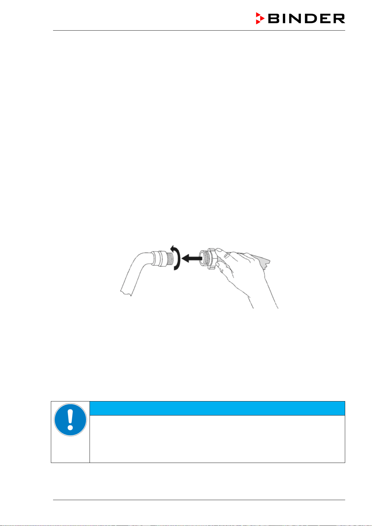
MKF / MKFT (E5) 06/2020 page 34/176
4.5 Connection kit for connecting the chamber’s freshwater connection to a
water pipe
A safety kit against flooding caused by burst water hoses is enclosed with the chamber. It consists of the
following:
• Hose burst protection device
• Hose nozzle with screwing
• 4 hose clamps
• 6m water hose, divisible for the feed hose and drain
Protection principle of hose burst protection:
Whenever a strong water flow of approx. 18 l / min. occurs, e.g. caused by a burst water hose, a valve
automatically cuts off the water supply, which can be heard as a clicking noise. The water supply now
remains shut until it is manually released.
Assembly:
Screw the hose burst protection device onto a water tap with a G¾ inch right turning thread connection.
The connection is self-sealing. Establish the connection between the safety kit and the chamber with a
part of the supplied hose. Protect both ends of the hose by the supplied hose clamps.
We recommend connecting the hose as the last step in order to avoid twisting the hose while screwing on
the safety kit.
Open the water tap slowly in order to avoid actuating the hose burst protection device.
Figure 12: Assembly of the connection kit
Release of the reflux protection device:
In case the burst protection device has interrupted the water supply, first find the reason and remove it as
necessary. Close the water tap. Release the valve by a half left-turn of the upper knurled part. You can
hear the release of the valve as a clicking noise. Tighten the burst protection device against the water tap
by a right turn. Open the water tap slowly afterwards.
Maintenance of the assembly of the hose burst protection device:
Calcification can impair valve function. We recommend an annual inspection by a skilled plumber. The
plumber should demount the safety kit to check the valve by hand for function, calcification or blockage.
NOTICE
Danger of impairment of the valve function by calcification.
Damage to the chamber.
Have a plumber inspect the valve annually.
Remove calcifications by citric acid or acetic acid solutions.
Continue by testing the function and tightness of the mounted chamber
Check: Quickly open the water tap while there is no chamber connected – the valve should cut off the
water flux without any delay.
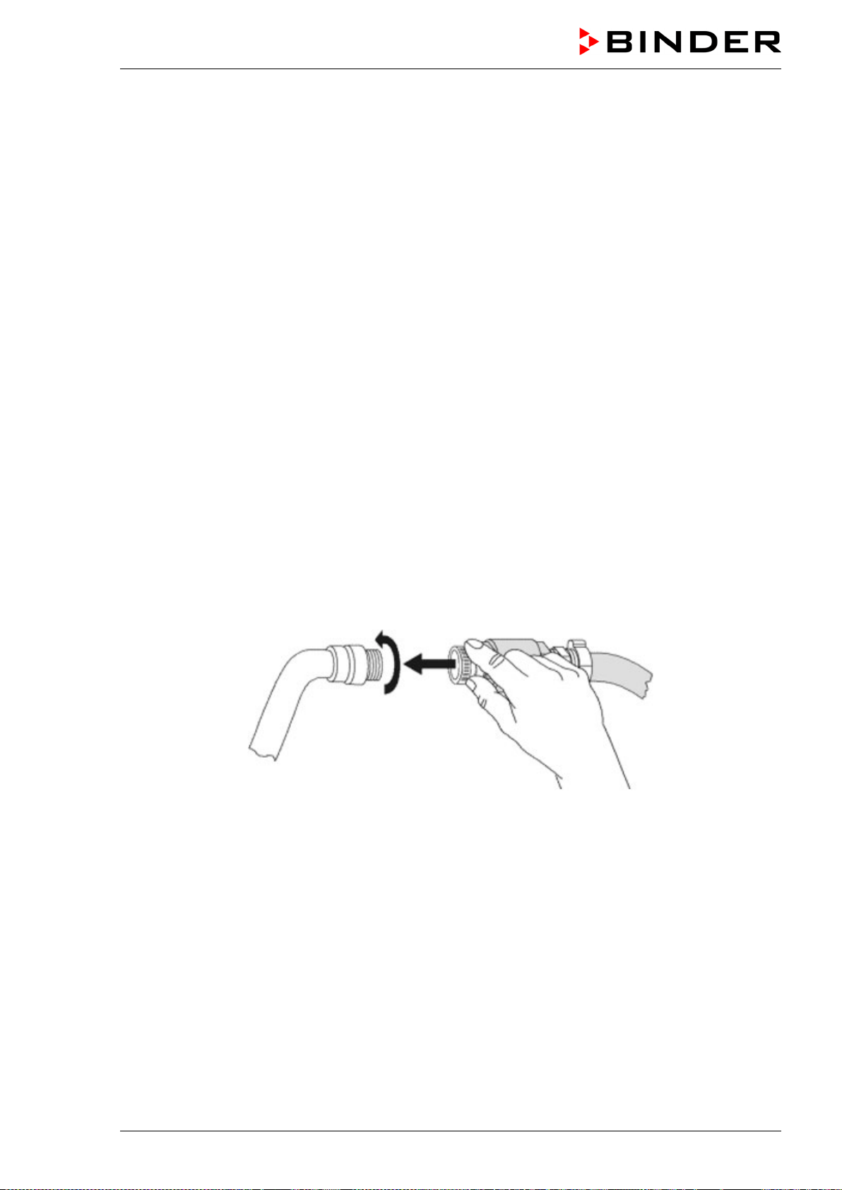
MKF / MKFT (E5) 06/2020 page 35/176
4.6 Safety kit: Hose burst protection device with reflux protection device for
the chamber’s freshwater connection (available via BINDER INDIVIDUAL
customized solutions)
A safety kit with a reflux protection device is available for protection of the drinking water system and
against flooding caused by burst water hoses.
Protection principles:
Whenever a strong water flow of approx. 18 l / min. occurs, e.g. caused by a burst water hose, a valve
automatically cuts off the water supply, which can be heard as a clicking noise. The water supply now
remains shut until it is manually released.
A possible endangering of the drinking water system depends on the risk potential of the charging materi-
al. Under unfavorable conditions (e.g. decreasing pressure inside the tap water system), drained off
charging material could be sucked out of the chamber via the steam generator into the tap water system
and therefore contaminate the drinking water. The safety kit with a reflux protection device provides secu-
rity in case of short-term utilization of substances with low risk potential. When using substances bearing
a higher risk potential, install a pipe disconnector to assure absolute protection. It is the user’s responsi-
bility to prevent (according to national standards) any reflux of contaminated water from getting into the
drinking water system.
Assembly:
The standard supplied parts – hose burst protection device, hose nozzle with screwing – are not needed.
Screw the pre-mounted assembly of the hose burst protection and reflux protection devices onto a water
tap with a G¾ inch right turning thread connection. The connection is self-sealing. Establish the connec-
tion between the safety kit and the chamber with a part of the supplied hose. Protect both ends of the
hose with the supplied hose clamps.
We recommend connecting the hose as the last step in order to avoid twisting it while screwing on the
safety kit.
Open the water tap slowly in order to avoid actuating the hose burst protection device.
Figure 13: Assembly of the safety kit: hose burst protection and reflux protection devices (option)
Release of the reflux protection device:
In case the hose burst protection device interrupts the water supply, first find the reason and remove it as
necessary. Close the water tap. Release the valve by a half left-turn of the upper knurled part. You can
hear the release of the valve as a clicking noise. Tighten the burst protection device against the water tap
by a right turn. Open the water tap slowly afterwards.
Maintenance of the assembly of hose burst protection and reflux protection devices:
Calcification can impair the function of both valves. We recommend an annual inspection by a skilled
plumber. The plumber should remove the safety kit with the reflux protection device to check both valves
by hand for proper function and calcification or blockage.
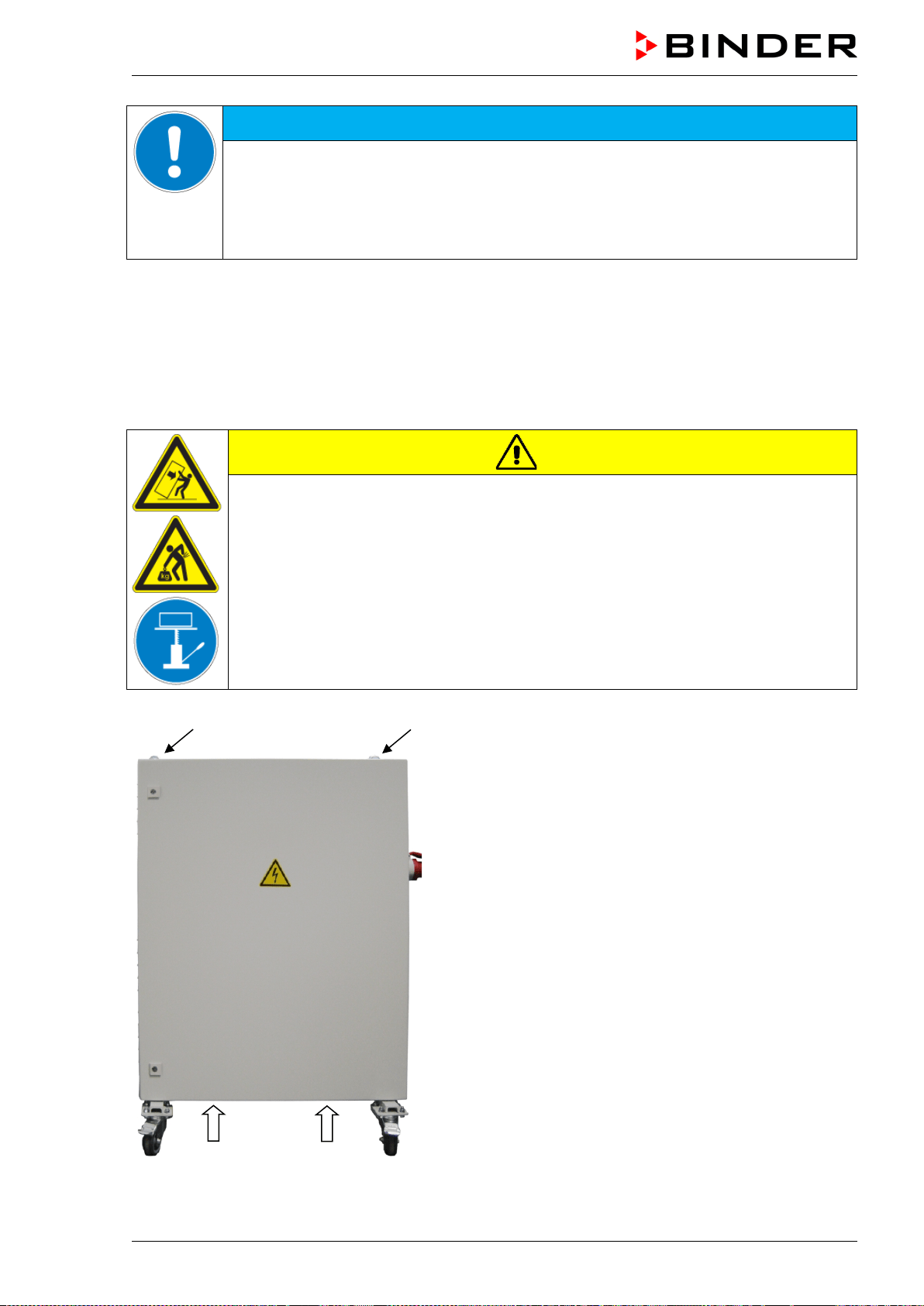
MKF / MKFT (E5) 06/2020 page 36/176
NOTICE
Danger of impairment of the valve function by calcification.
Damage to the chamber.
Have a plumber inspect the valve annually.
Remove calcifications by citric acid or acetic acid solutions.
Continue by testing the function and tightness of the mounted chamber
Check: Quickly open the water tap while there is no chamber connected – the valve should cut off the
water flux without any delay.
4.7 Installation of the voltage and frequency changer
(chambers with voltage and frequency changer)
The voltage and frequency changer is supplied packed separately together with the chamber.
CAUTION
Sliding or tilting of the voltage and frequency changer.
Damage to the voltage and frequency changer.
Risk of injury by lifting heavy loads.
∅ Do NOT lift the voltage and frequency changer by hand.
Lift the voltage and frequency changer from the pallet using technical devices (fork
lifter). Set the fork lifter only from the rear in the middle of the chamber.
Alternatively, the voltage and frequency changer can also be lifted at the eyelets on
the top by means of a lifting crane or fork lifter
(a) Eyelets for lifting with a lifting crane or fork lifter
(b) Positions for a fork lifter
Figure 14: Positioning of aids for lifting the voltage
and frequency changer
(b)
(a) (a)
(b)
MKF / MKFT (E5) 06/2020 page 37/176
For the installation of the voltage and frequency changer behind the chamber, provide a rear wall dis-
tance of the chamber of approx. 1 m / 3.3 ft.
If possible, fix the voltage and frequency changer at the chamber. For this purpose, an Allen key size 4 is
required. Connect the slots at the end of the chassis with two M6 screws to the threads provided below
on the rear panel of the chamber (see Figure 15).
NOTICE
Danger of overheating due to lack of ventilation.
Damage to the voltage and frequency changer.
∅ Do NOT install the voltage and frequency changer in unventilated recesses.
Ensure sufficient ventilation for dispersal of the heat.
The voltage and frequency changer is equipped with four castors. The rear castors can be easily locked
via the attached brakes
4.8 Electrical connection
4.8.1 Information on connecting the alternating climate chamber
The chambers are supplied ready for connection.
MKF 56: The chambers come with an IEC connector plug. They are equipped with an internal overload
release against excess-current.
MKF/MKFT 115,240,720: The chambers come with a fixed power connection cable of at least 1800 mm /
70.87 in in length. They are equipped with three internal overload releases against excess-current.
Model Power plug
Nominal voltage +/- 10% at the
indicated power frequency
Current
type
Chamber
fuse
MKF 56 (230V)
IEC connector plug
(grounded plug)
230 V at 50 Hz
1 N~
16 Amp
internal
MKF 56 (240V)
IEC connector plug
(grounded plug)
240 V at 60 Hz 2~
16 Amp
internal
MKF 115
MKFT 115
MKF 240
CEE plug 5-poles
16 Amp
400 V at 50 Hz
3 N~
16 Amp
3 x internal
MKFT 240
CEE plug 5-poles
16 Amp
400 V at 50 Hz 3 N~
16 Amp
3 x internal
MKF 720
MKFT 720
CEE plug 5-poles
32 Amp
400 V at 50 Hz 3 N~
25 Amp
3 x internal
• The domestic socket must also provide a protective conductor. Make sure that the connection of the
protective conductor of the domestic installations to the chamber’s protective conductor meets the lat-
est technology. The protective conductors of the socket and plug must be compatible!
DANGER
Electrical hazard due to missing protective conductor connection.
Deadly electric shock.
Make sure that the chamber’s power plug and the power socket match and secure-
ly connect the electrical protective conductors of the chamber and the house instal-
lation.
MKF / MKFT (E5) 06/2020 page 38/176
• Prior to connection and start-up, check the power supply voltage. Compare the values to the specified
data located on the chamber’s type plate (left chamber side, bottom right-hand, chap. 1.6).
NOTICE
Danger of incorrect power supply voltage due to improper connection.
Damage to the chamber.
Check the power supply voltage before connection and start-up.
Compare the power supply voltage with the data indicated on the type plate.
• When connecting, please observe the regulations specified by the local electricity supply company
and as well as the VDE directives (for Germany). We recommend the use of a residual current circuit
breaker.
• Only use original connection cables from BINDER according to the above specification.
• Pollution degree (acc. to IEC 61010-1): 2
• Over-voltage category (acc. to IEC 61010-1): II
See also electrical data (chap. 25.4 and 25.5).
To completely separate the chamber from the power supply, you must disconnect the power
plug. Install the chamber in a way that the power plug is easily accessible and can be easily
pulled in case of danger.
4.8.2 Connecting the voltage and frequency changer (for chambers equipped with a
voltage and frequency changer)
The voltage and frequency changer is supplied with a fixed power connection cable without a plug. It is
protected against excess-current with 3 internal overload releases. The connection is made by the cus-
tomer.
The socket must provide a protective conductor.
Electrical connection data:
• Input side: 480 V, 60 Hz, 4-wire
• Output side (to the chamber): 400 V, 50 Hz, 5-wire
To establish the electrical connection of the alternating climate chamber with the voltage and frequency
changer, proceed in the following order:
1. Connect the chamber to the connection socket (G) of the voltage and frequency changer
2. Establish the power connection of the voltage and frequency changer using the power cable (I)
3. Turn on the voltage and frequency changer at the power switch (H) (position “ON”)
4. Turn on the chamber with the main power switch (3) in the lateral control panel
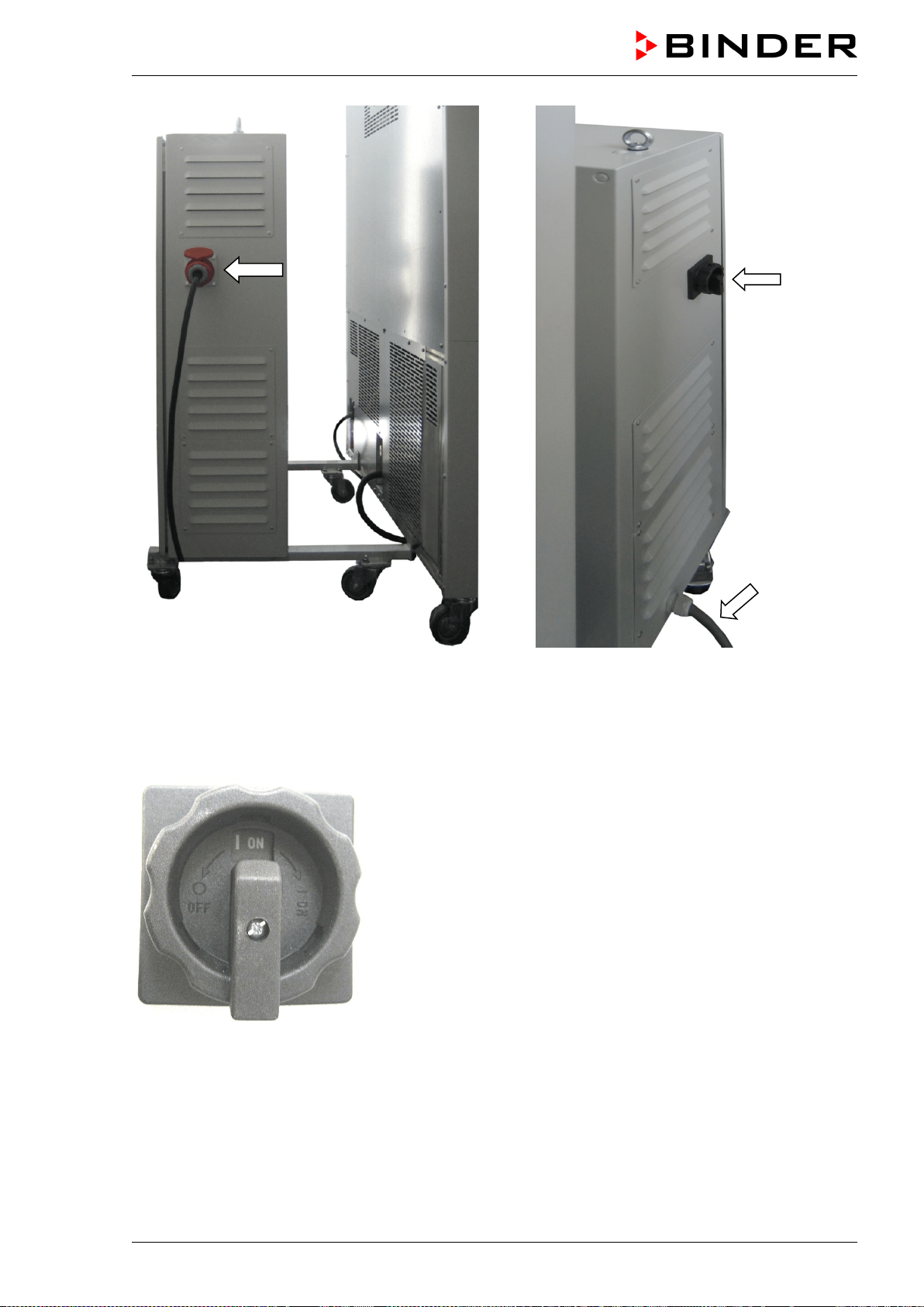
MKF / MKFT (E5) 06/2020 page 39/176
Left side of the voltage and frequency changer
with connection socket (G) for the alternating climate
chamber
Right side of the voltage and frequency changer
with power switch (H) and power cable (I)
Figure 15: Voltage and frequency changer, mounted
Figure 16: Power switch (H) of the voltage and frequency chang-
er in position “ON”
In position “OFF” the switch can be locked, e.g. with a padlock.
(G)
(H)
(I)
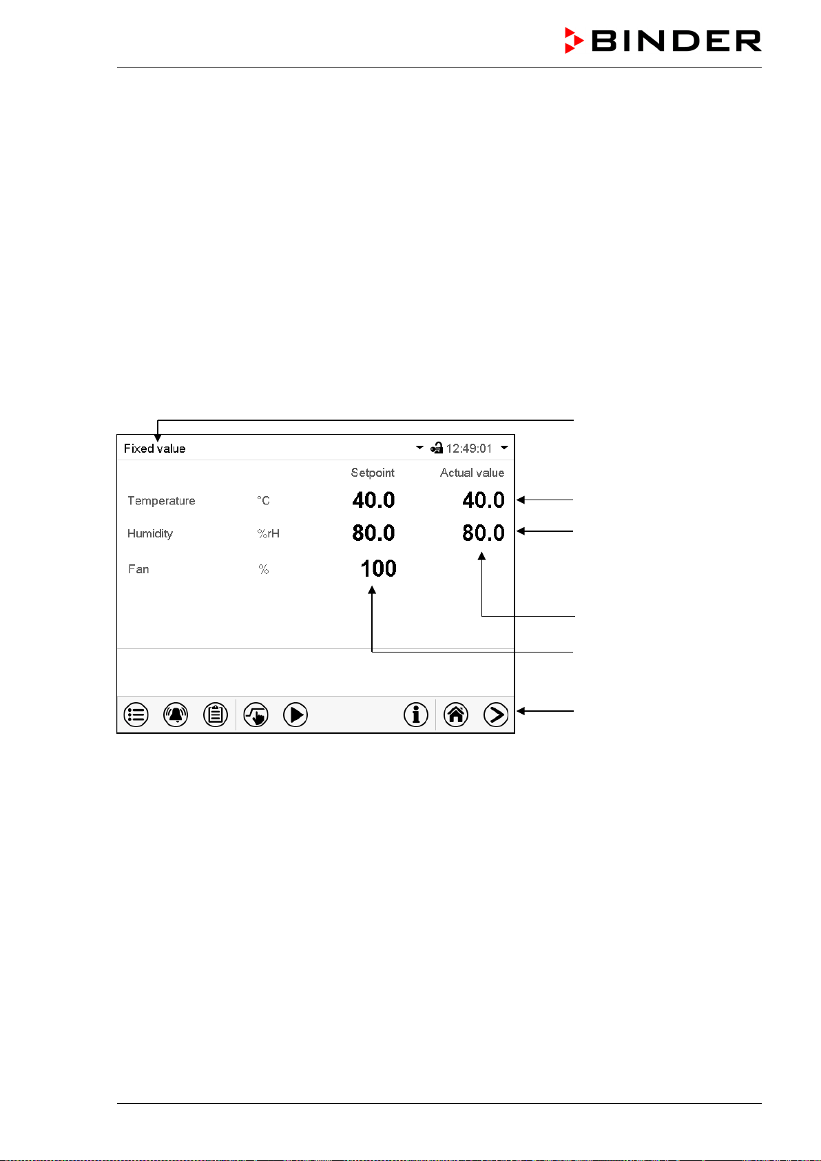
MKF / MKFT (E5) 06/2020 page 40/176
5. Functional overview of the MB2 chamber controller
The MB2 chamber controller controls following parameters inside the chamber:
• Temperature in °C
• Relative humidity in % r.h.
• Fan speed in % (adjustable only with MKF 56)
For the control ranges of temperature and humidity, see climatic diagrams (chap. 17).
You can enter the desired set point values in fixed value operation mode directly on the display surface or
via the setpoint menu. For program operation the controller offers programming week and time programs.
In addition there is a timer program available (stopwatch function).
The controller offers various notifications and alarm messages with visual and audible indication and re-
mote alarms via e-mail, an event list (trace file) and the graphical display of the measuring values in the
in der chart recorder view. The MB2 program controller permits programming temperature and humidity
cycles, and specifying the fan speed (MKF 56) and special controller functions for each program section.
You can enter values or programs directly at the controller or use the APT-COM™ 4 Multi Management
Software (option) specially developed by BINDER.
Operating mode
Temperature values
Humidity values
Actual values
Set-point values
Functional icons
Figure 17: Normal display of the MB2 program controller (sample values, MKF 56)
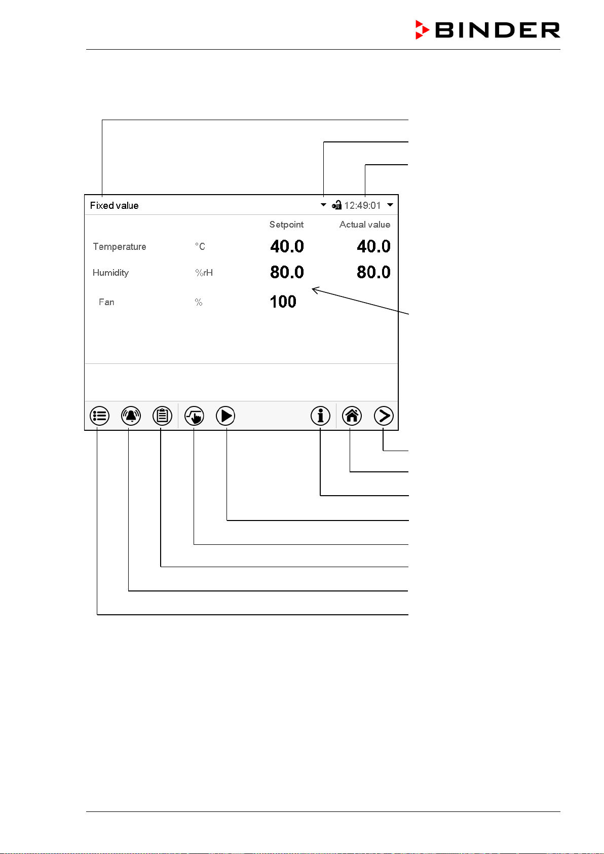
MKF / MKFT (E5) 06/2020 page 41/176
5.1 Operating functions in normal display
Current operating mode
Text list for information icons
Date, time, authorization level of
the logged-in user, memory
Quick setpoint entry
Continue to next screen
Back to Normal display
Information
Program start
Setpoint entry
Event list
Display of active alarms
Access to main menu
Figure 18: Operating functions of the MB2 controller in normal display (sample values, MKF 56)
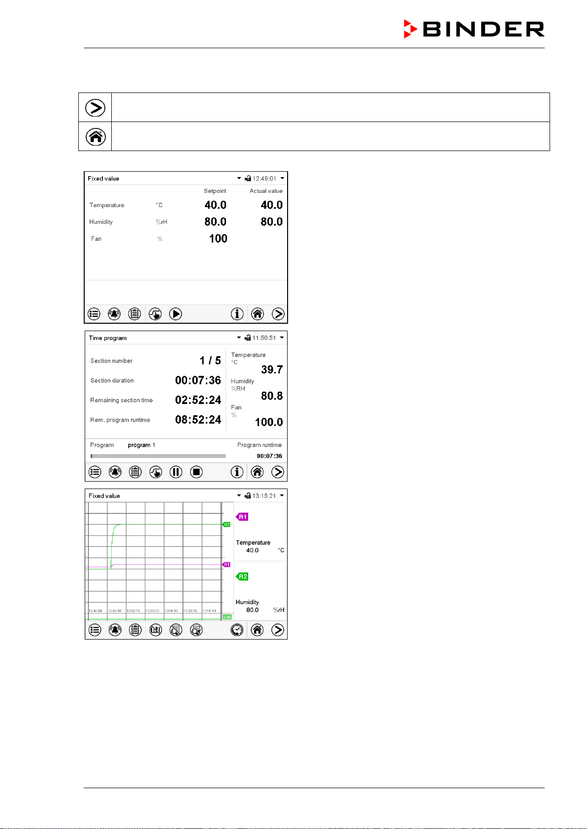
MKF / MKFT (E5) 06/2020 page 42/176
5.2 Display views: Normal display, program display, chart-recorder display
Press the Change view icon to toggle between normal display, program display and chart-
recorder display.
Press the Normal display icon to return from program display and chart recorder display back to
Normal display.
Normal display (actual values / setpoint values)
Program display (example: time program)
Chart recorder display
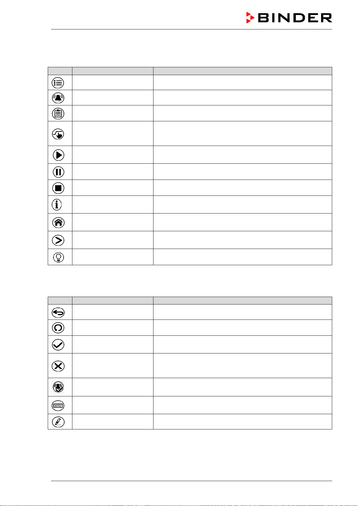
MKF / MKFT (E5) 06/2020 page 43/176
5.3 Controller icons overview
Navigation icons in Normal display
Icon
Signification
Function
Main menu Access from Normal display to the main menu
Alarm Access from Normal display to the list of active alarms
Event list Access from Normal display to the event list
Setpoint setting
Access from Normal display to the setpoint entry menu: setpoint
entry for Fixed value operation, turning on/off humidity control,
safety controller settings
Program start
Start a previously entered time or week program,
continue a paused time program
Program pause Pause a running time program
Program cancelling Cancel a running time or week program
Information
Information on program operation, setpoints, actual values, and
the safety controller
Normal display
Return from program display or chart recorder display to Normal
display
Change view
Toggle between Normal display, program display, and chart
recorder display
Interior lighting Turn on and off the interior lighting
Functional icons in individual menus
Icon
Signification
Function
Back Return from each menu to Normal display
Update Update the event list and alarm messages
Confirm
Take over the entries and exit the menu / continue menu se-
quence.
Close
Exit the menu / cancel menu sequence. Entries are not taken
over. When terminating a menu sequence, an information win-
dow appears, which must be confirmed.
Reset alarm Acknowledge the alarm and mute the buzzer.
Change keyboard
Change between uppercase and lower case characters, digits
and special characters
Edit Edit settings of time and week programs
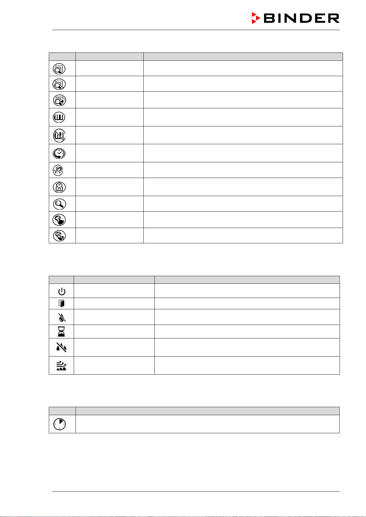
MKF / MKFT (E5) 06/2020 page 44/176
Functional icons in the chart recorder display
Icon
Signification
Function
Show legend Show legend
Hide legend Hide legend
Switch legend Switch between legend pages
Show indications
Show indication “Door open” (B1), “Anti-condensat.” (B2) and “Com-
pressed air” (B3)
Hide indications
Hide indication “Door open” (B1), “Anti-condensat.” (B2) and “Com-
pressed air” (B3)
History display
Pause chart recorder and change to history display. Data recording
continues.
Curve selection Go to “Curve selection” submenu in the history display
Search
Go to “Search” submenu in the history display to select the required
instant
Zoom Go to “Zoom” submenu in the history display to select the zoom factor
Show scroll buttons Show scroll buttons in the history display to scroll to an instant
Hide scroll buttons Hide scroll buttons in the history display to scroll to an instant
Information icons referring to chamber conditions
Icon
Text information
Condition
“Idle mode” Controller is in Idle mode
“Door open” Chamber door is open
“Humidity off” The humidification / dehumidification system is turned off
“Preheating phase 1-hour preheating phase, no cooling or dehumidification function
“Anti-condensation”
Operation line “Anti-condensation” on: anti-condensation protec-
tion activated
Compressed Air Dryer
Compressed air dryer (option) activated with operation line
“Compr. air dryer” (MKF/MKFT 115, 240, 720)
Information icon for data processing
Icon
Information
Waiting icon: Data processing is running.
Remaining time to touch the display when calibrating the touchscreen.
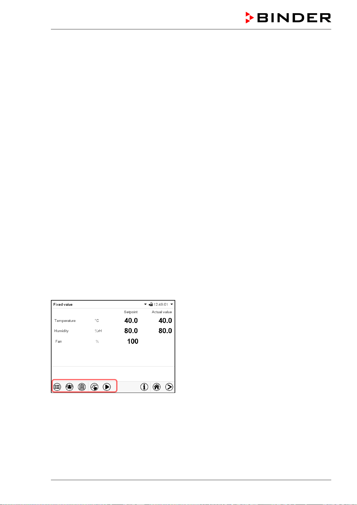
MKF / MKFT (E5) 06/2020 page 45/176
5.4 Operating modes
The MB2 program controller operates in the following operating modes:
• Idle mode
The controller is not functional, i.e., there is no heating or refrigeration and no humidification or dehu-
midification. The fan is off. The chamber approximates ambient values.
You can activate and deactivate this operating mode with the “Idle mode” control contact in Fixed val-
ue operating mode (chap. 7.3), time program operation (chap. 9.7.3) and week program operation
(chap. 10.6.5).
• Fixed value operating mode
The controller operates as a fixed-point controller, i.e., set-points can be defined, which are then main-
tained until the next manual change (chap. 7.1).
• Timer program operation
Stopwatch function: during an entered duration the controller constantly equilibrates to the setpoints
entered in Fixed value operation mode.
• Time program operation
An entered time program for temperature and humidity is running. The controller offers 25 program
memory places with 100 program sections each. The total number of program sections of all programs
is unlimited
• Week program operation
An entered week program for temperature and humidity is running. The controller offers 5 program
memory places with 100 switching points each. The switching points can be distributed over all days
of the week.
5.5 Controller menu structure
Use the navigation icons in the screen footer in Normal display to access the desired controller func-
tions.
The available functions depend on the current authorization level “Service”, “Admin” or “User” (chap.
13.1). This is selected either during login or can be available without password protection.
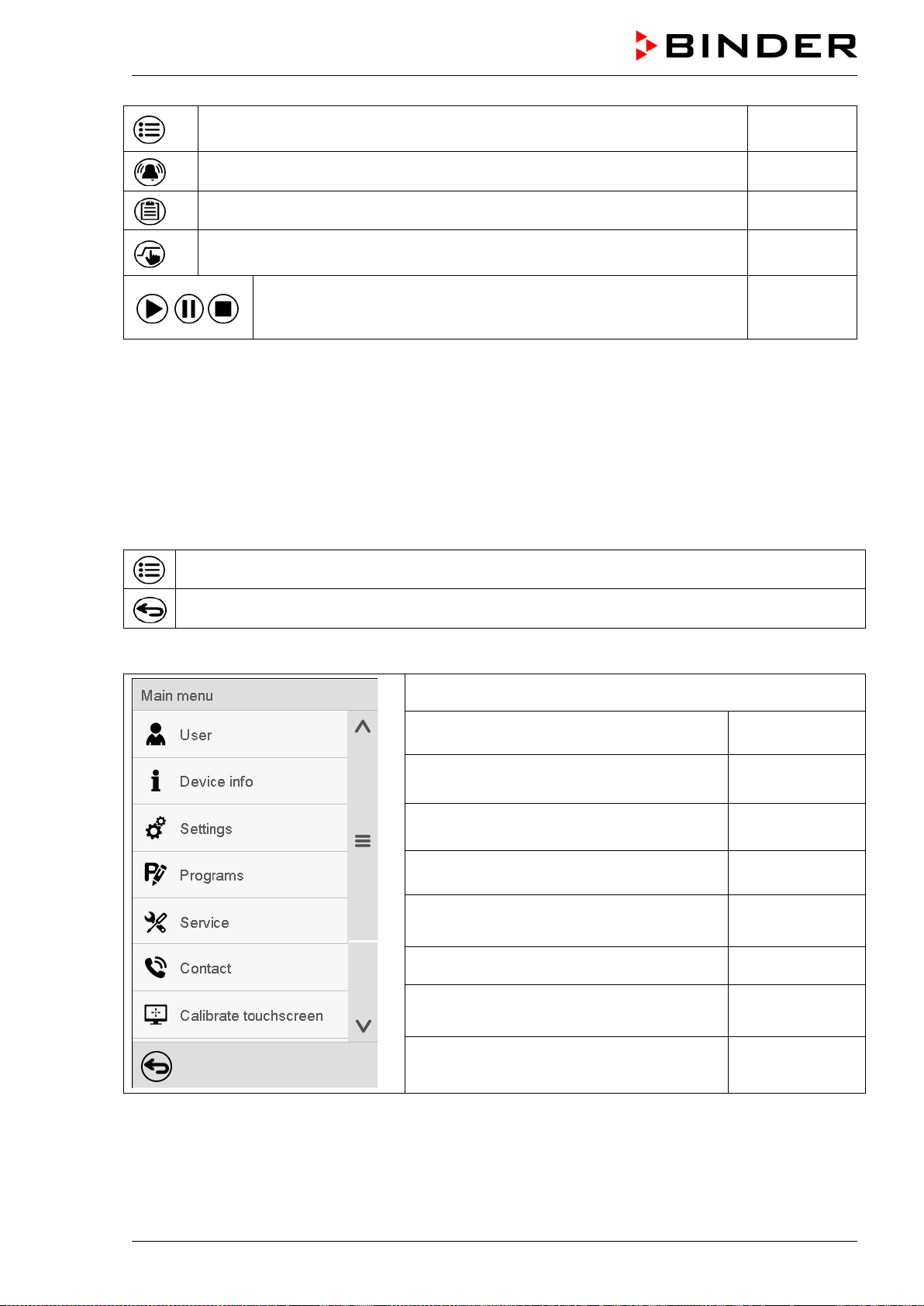
MKF / MKFT (E5) 06/2020 page 46/176
Main menu: program settings, further information, “Service” submenu.
The “Settings” submenu allows general configuration of the controller.
chap. 5.5.1
List of active alarms chap. 11
Access to the event list chap. 15.2
Setpoint entry for Fixed value operation, turning on/off humidity control,
safety controller settings
chap. 7, 6.3,
12.2
Start/ pause/ cancel an already entered, respectively a running time
program or start / cancel an already entered, respectively a running
week program
chap. 9.1,
9.2, 10.1
Unless noted otherwise, the figures show the functional range, which is available for the user with “Ad-
min” authorization level.
5.5.1 Main menu
The main menu provides access to the general configuration of the controller as well as to program entry
and the user administration. Additionally there are support functions like a contact page or the display
calibration depending on the available angle.
Press the Main menu icon to access the main menu from Normal Display.
Press the Back icon to return from each setting menu to Normal Display.
The main menu provides the following functions and submenus.
User management: login and logout, pass-
word management
chap. 13
Chamber information chap. 15.2
“Settings” submenu (not visible for user with
“User” authorization level)
chap. 14
Program entry submenu for time and week
programs
chap. 9 and 10
“Service” submenu chap. 5.5.3
BINDER Service contact page chap. 15.1
Calibrating the touch screen chap. 14.4.2
Back to Normal Display
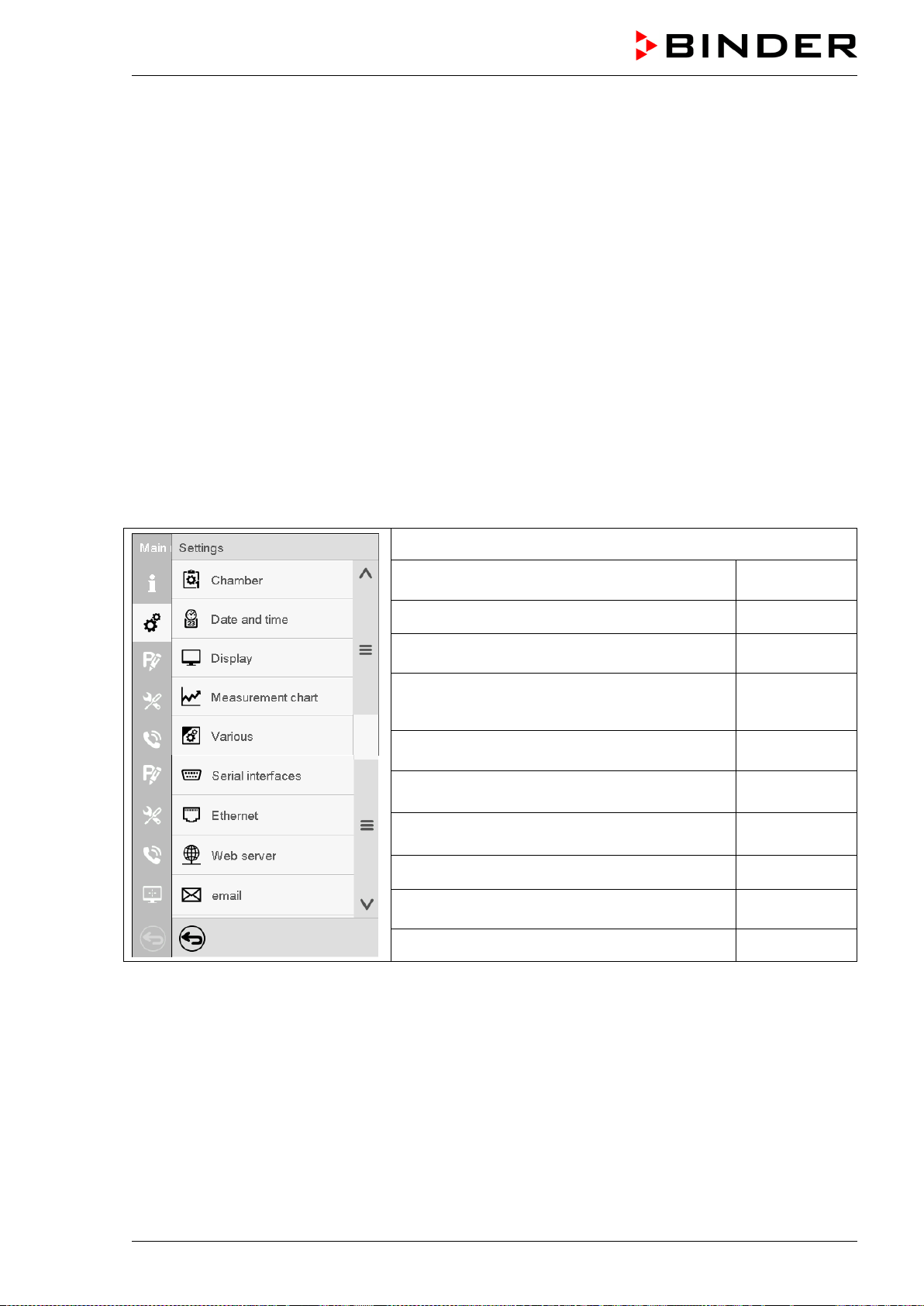
MKF / MKFT (E5) 06/2020 page 47/176
“Settings” submenu
• Settings of many general controller functions and network settings (chap. 14).
• Available only for users with “Service” and “Admin” authorization level
“Service” submenu
• Access to service data, controller reset to factory settings (chap. 5.5.3)
• Available only for users with “Service” and “Admin” authorization level. Full functional range only for
BINDER Service (users with “Service” authorization level).
“Programs” submenu
• Access to the controller’s program functions (chap. 8, 9, 10)
5.5.2 “Settings” submenu
The “Settings” submenu is available for users with “Service” or “Admin” authorization level. It serves to
enter date and time, select the language for the controller menus and the desired temperature unit and to
configure the controller’s communication functions.
Path: Main menu > Settings
Setting the temperature unit, menu language…
chap. 14.1,
14.2
Setting date and time chap. 14.2
Setting the display brightness, continuous op-
eration and screen saver
chap. 14.4
Settings for the measurement chart: storage
interval, storage values, minimum and maxi-
mum values
chap. 16.2
Turning off the interior lighting automatically chap. 14.7
Configuration of the optional RS485 interface,
setting of the device address
chap. 14.5.1
Entry of the MAC address and IP address chap. 14.5.2
Password protection for web server access chap. 14.5.3
Configuration of the e-mail server, assignment
of e-mail addresses
chap. 14.5.4
Back to main menu
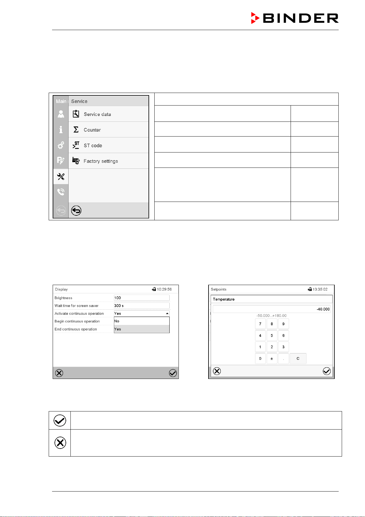
MKF / MKFT (E5) 06/2020 page 48/176
5.5.3 “Service” submenu
The “Service” submenu is available for users with “Service” or “Admin” authorization level. When logged-
in with “Admin” authorization level the user will find information to tell the BINDER Service in service
case.
Path: Main menu > Service
Serial number of the chamber, setup version of
the controller software
chap. 14.2
No function
Information for BINDER Service
Reset to factory settings
Back to main menu
(view with “Admin” authorization level)
5.6 Principle of controller entries
In the selection and entry menus there are icons displayed in the footers which you can use to take over
the entry or cancel it.
Selection menu (example)
Entry menu (example)
After completing the settings there are the following possibilities:
Press the Confirm icon to take over the entries and exit the menu or continue the menu se-
quence.
Press the Close icon to exit the menu or cancel the menu sequence without taking over the en-
tries.
When terminating a menu sequence, an information window appears, which must be confirmed.

MKF / MKFT (E5) 06/2020 page 49/176
5.7 Performance during and after power failures
During a power failure, all controller functions are shut down.
After the power returns, all functions return to the same status the chamber had before power failure. The
controller continues to function in the original operating mode it was in previously before the power failure
occurred.
• Performance after power failure in Idle mode
Control is deactivated
• Performance after power failure in Fixed value operation mode
All functions return to the same status the chamber had before power failure. The set-points are im-
mediately resumed.
• Performance after power failure during time program operation
The program is resumed at the point where the interruption occurred with the latest set-points reached
during the program run.
• Performance after power failure during week program operation
The week program continues with the values corresponding to the current time.
Power failure and power return are noted in the event list (chap. 15.3).
If during power failure an alarm has occurred (tolerance range, safety controller, optional over/under tem-
perature safety device class 2), confirm the alarm. See chap. 11.3.
5.8 Performance when opening the door
MKF 56: Immediately after opening the door, the fan runs at the minimum speed (30%). 60 seconds after
opening the door, the fan turns off.
MKF/MKFT 115, 240, 720: The fan turns off immediately after opening the door.
After 60 seconds from opening the door, heating, refrigeration, humidification, dehumidification and fan
turn off. The compressor continues operating during 5 minutes without cooling function.
After closing the door, heating, refrigeration, humidification, dehumidification and fan turn on again.
MKF / MKFT (E5) 06/2020 page 50/176
6. Start up
6.1 Turning on the chamber
After connecting the supply lines (chap. 4), you can start up the chamber.
• MKF 56: Turn on the main power switch (1) in the lateral control panel at least one hour before operat-
ing the chamber.
• MKF/MKFT 115, 240, 720: Turn on the main power switch (1) in the lateral control panel and the rear
power switch (12) at least one hour before operating the chamber
• The lit pilot lamp shows the chamber is ready for operation. When the chamber has been turned on
and yet the controller display is dark, the display is in stand-by mode. Press on the touchscreen to ac-
tivate it.
• Open the water-tap for supply. Alternatively, fill the freshwater can (internal water can: regular with
MKF/MKFT 115, 240, 720, external water can: optional for MKF 56).
• The humidifying and dehumidifying system must be activated (deactivated operation line “Humidity
off”, chap. 7.3 and setting “Control on”, chap. 6.3).
After the first turning on of the humidity or after an interruption of the power supply the relative humidity
will increase after a delay of approx. 20 minutes. During this period, the relative humidity can drop con-
siderably.
MKF 56: The refrigerating and dehumidification functions are available only one hour after turning on the
main power switch (1). This is indicated by the information message “Preheating phase” in the controller
display.
MKF/MKFT 115, 240, 720: The refrigerating and dehumidification functions are available only one hour
after turning on the main power switch (1) and the rear power switch (12). This is indicated by the infor-
mation message “Preheating phase” in the controller display. After 1 minute the information message
“Water can empty” appears on the controller display. You can reset this message only after the 1-hour
preheating phase.
Warming chambers may release odors in the first few days after commissioning. This is not a quality de-
fect. To reduce odors quickly we recommend heating up the chamber to its nominal temperature for one
day and in a well-ventilated location.
For control reasons the refrigeration machine starts with a delay time. The refrigeration ma-
chine also turns off with a 5 minutes delay. This explains why the compressor may remain
operating also during positive temperature jumps.
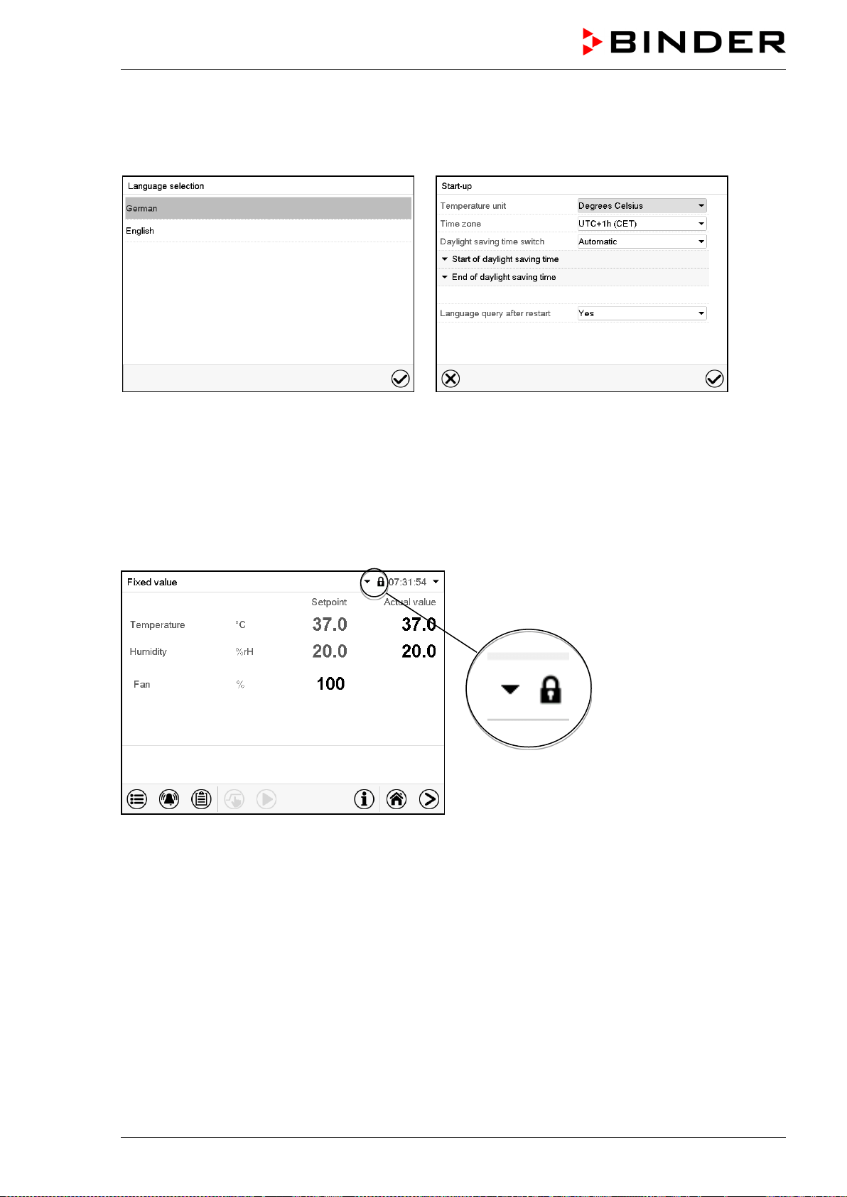
MKF / MKFT (E5) 06/2020 page 51/176
6.2 Controller settings upon start up
The window “Language selection” enables the language selection, in case that it’s activated in the
“Start-up” menu. Afterwards occurs a request of the time zone and the temperature unit.
The controller will function in the operating mode, which was active before the last shut-down. It controls
temperature in fixed value operating mode to the last entered values and in the program mode to the set
points achieved beforehand.
Locked operation
Provided that the user administration has been activated by the assignment of passwords for the different
authorization types, the controller operation is first locked after turning on the unit, recognizable by the
closed lock icon in the header.
In the locked view the controller provides all display functions. No setting functions are available.
The setpoints are shaded (light grey) in normal display. Changing them by direct entry in the fixed value
operating mode is not possible. The functional icons for setpoint entry and program start in the footer are
without function.
After turning on the unit, user log-in is required to operate the controller (chap. 13.2).
Operation without user log-in / without password-protection
If the password function has been deactivated, after turning on the unit without user log-in there are those
controller functions available, which correspond to the highest authorization level without a password
protection. There is no lock icon in the header.
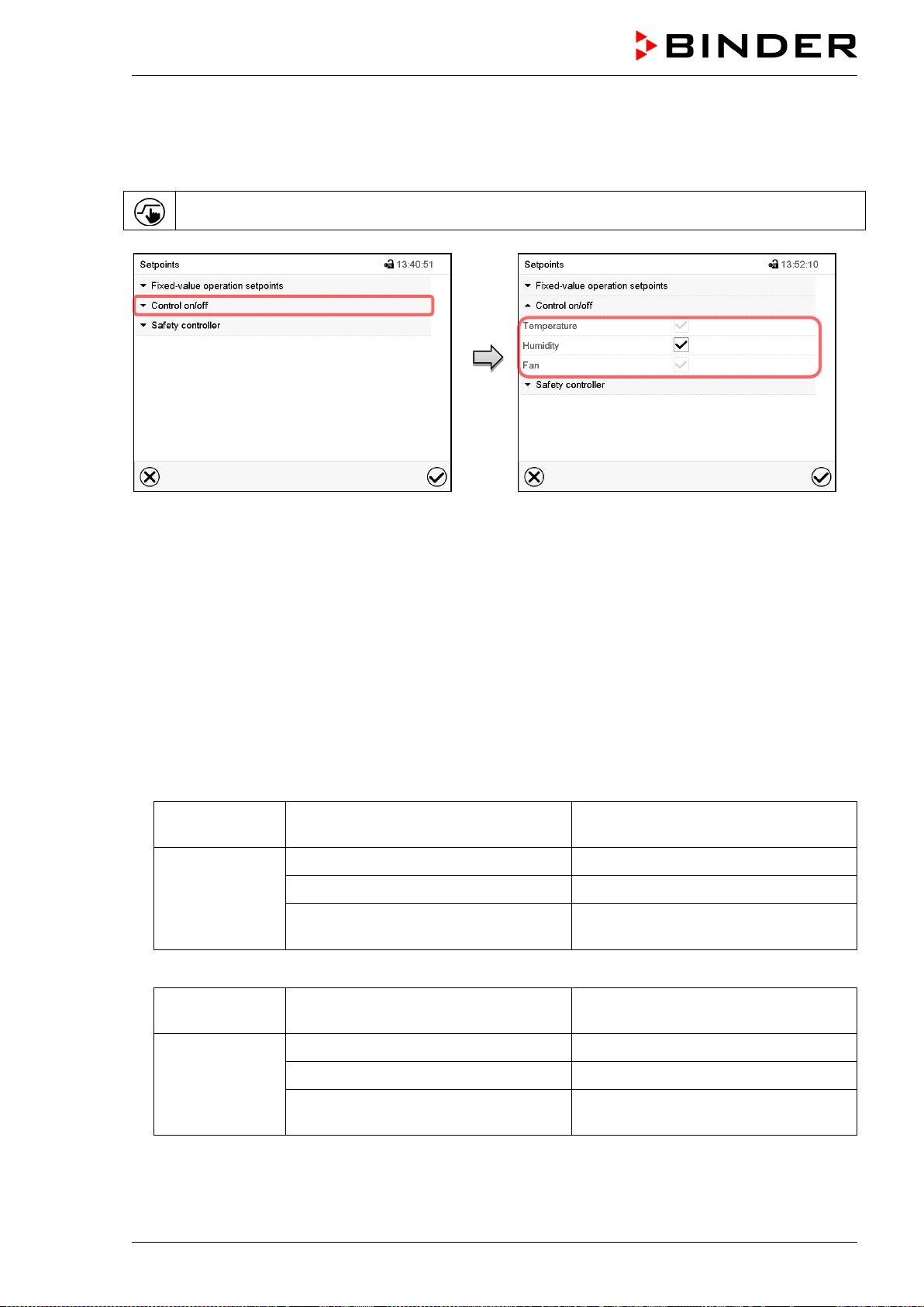
MKF / MKFT (E5) 06/2020 page 52/176
6.3 Turning on/off humidity control
Turning off humidity control is required when operating the chamber without water connection in order to
avoid humidity alarms. For further information see chap. 17.
Press the Setpoint setting icon to access the “Setpoint” setting menu from Normal display.
“Setpoints” menu.
Select “Control on/off”.
You can turn humidity control (humidification
and dehumidification) on or off.
If the “Humidity “checkbox is marked, humidity
control is active. Mark / unmark the checkbox to
change the setting.
7. Set-point entry in “Fixed value” operating mode
In Fixed value operating mode you can enter a temperature set-point, the fan speed (MKF 56), and the
switching-state of up to 16 operation lines.
All settings made in Fixed value operating mode remain valid until the next manual change. They are
saved also when turning off the chamber or in case of toggling to Idle Mode or Program Mode.
• Temperature – MKF
Setting range -50 °C / -58 °F up to 180 °C / 356 °F
(range -50 °C / -58 °F up to -40 ºC /
-40 °F not provided for operation)
Control ranges
-40 ºC / -40 °F up to 180 °C / 356 °F without humidity
+ 10 °C / 50 °F up to +95 °C / 203 °F in climatic operation
0 °C / 32 °F up to +95 °C / 203 °F
in climatic operation with optional com-
pressed air dryer
• Temperature – MKFT
Setting range -80 °C / -112 °F up to 180 °C / 356 °F
(range -80 °C / -112 °F up to -70 ºC /
-94 °F not provided for operation)
Control ranges
-70 ºC / -94 °F up to 180 °C / 356 °F without humidity
+ 10 °C / 50 °F up to +95 °C / 203 °F in climatic operation
0 °C / 32 °F up to +95 °C / 203 °F
in climatic operation with optional com-
pressed air dryer
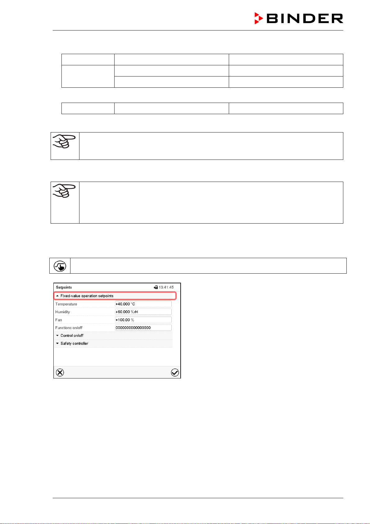
MKF / MKFT (E5) 06/2020 page 53/176
• Humidity
Setting range 0% r.h. up to 100 % r.h.
Control ranges
10 % r.h. up to 98 % r.h.
5 % r.h. up to 98% r.h. with optional compressed air dryer
• Fan speed (MKF 56)
Setting range 30 % up to 100 %
See temperature / humidity diagrams in chap. 17
MKF 56: Reduce the fan speed only if required, because the spatial temperature distribution
of will also be reduced.
Technical data refers to 100% fan speed.
For the control range of temperature and relative humidity, see the temperature / humidity diagram (chap.
17).
With set-point type “Limit”, adapt the safety controller (chap. 12.2) or the over/under tempera-
ture safety device class 2 (option, chap. 12.3) always when you changed the temperature set-
point. Set the safety controller set-point or the set-point of the over/under temperature safety
device class 2 (option) by approx. 2 °C to 5 °C above the controller temperature set-point.
Recommended setting: Set-point type “Offset” with safety controller set-point 2 °C.
7.1 Set-point entry through the “Setpoints” menu
Press the Setpoint setting icon to access the “Setpoint” setting menu from Normal display.
“Setpoints” menu (example: MKF 56).
Select “Fixed value operation setpoints” to access the
individual parameters.
• Select the field “Temperature” and enter the desired temperature setpoint.
Setting range: MKF: -50 °C up to 180 °C, MKFT: -80 °C up to 180 °C.
Confirm entry with Confirm icon.
• Select the field “Humidity” and enter the desired humidity setpoint.
Setting range: 0% r.h. up to 100% r.h. Confirm entry with Confirm icon.
• MKF 56: Select the field “Fan” and enter the desired fan speed setpoint.
Setting range: 30% up to 100% fan speed. Confirm entry with Confirm icon.
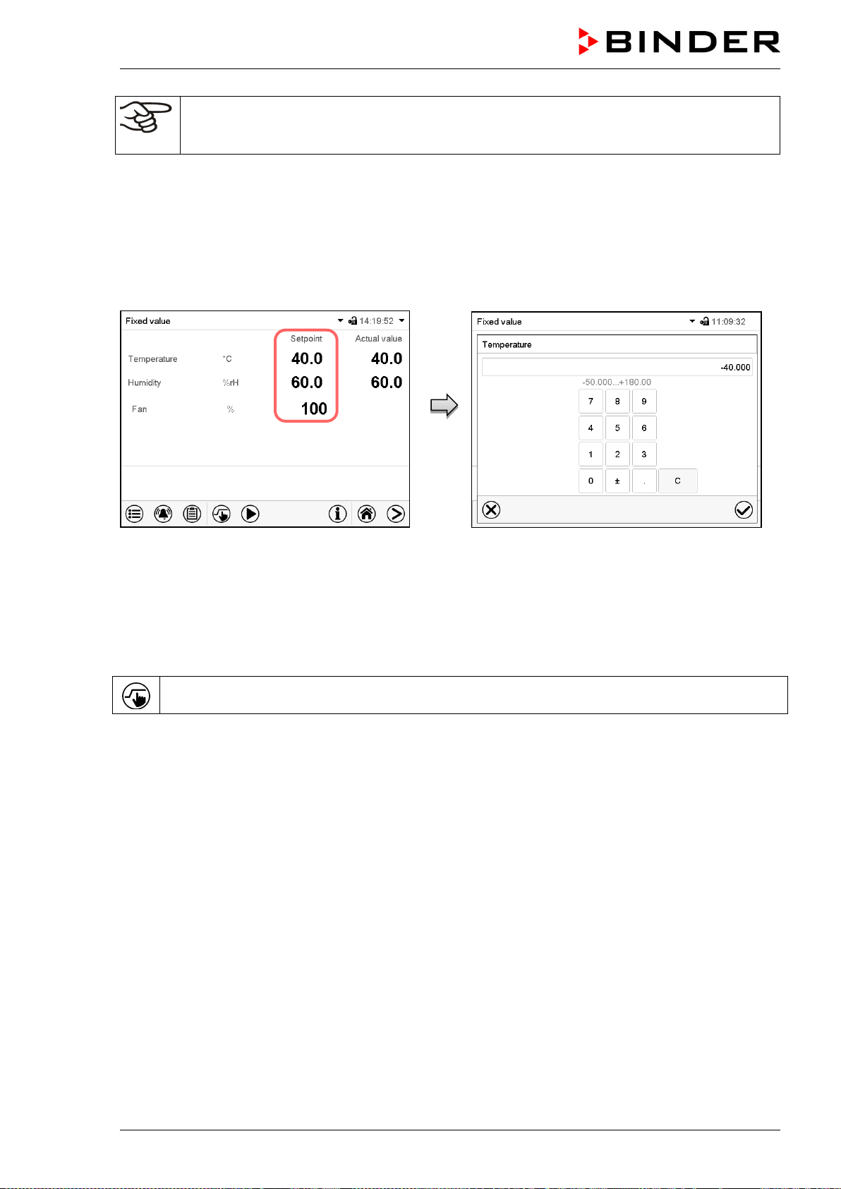
MKF / MKFT (E5) 06/2020 page 54/176
When entering a value outside the setting range, the message: “Value outside of limits! (Min:
xxx, Max: xxx)” appears (xxx is a wildcard for the limits of the respective parameter). Press the
Confirm icon and repeat the entry with a correct value.
After completing the settings, press the Confirm icon to take over the entries and exit the menu, or press
the Close icon to exit the menu without taking over the entries.
7.2 Direct setpoint entry via Normal display
Alternatively you can also enter the setpoints directly via Normal display.
Normal display (example: MKF 56).
Select the setpoint you want to change.
Example: “Temperature” entry menu.
Enter the desired setpoint and confirm entry
with Confirm icon
7.3 Special controller functions via operation lines
Press the Setpoint setting icon to access the “Setpoint” setting menu from Normal display.
You can define the switching state of up to 16 operation lines (control contacts). They are used to activate
/ deactivate special controller functions.
• Operation line “Humidity off” serves to turn off the humidity.
• Operation line Idle mode” activates / deactivates the operating mode “Idle mode”.
• Operation lines “Switching output 1” up to “4” can be used to turn on and off any equipment connected
to the zero-voltage switching outputs (DIN sockets (7) and (8) (chap. 20).
• Operation line “Compr. air dryer” serves to activate the compressed air dryer (option, chap. 21.6).
• Operation line “Compressed air valve” serves to open the solenoid valve of the compressed air con-
nection (for options compressed air connection, chap. 21.5, or compressed air dryer, chap. 21.6)
• Operation line “Anti-condensation” serves to switch the anti-condensation protection (chap. 19).
The other operation lines are without function.
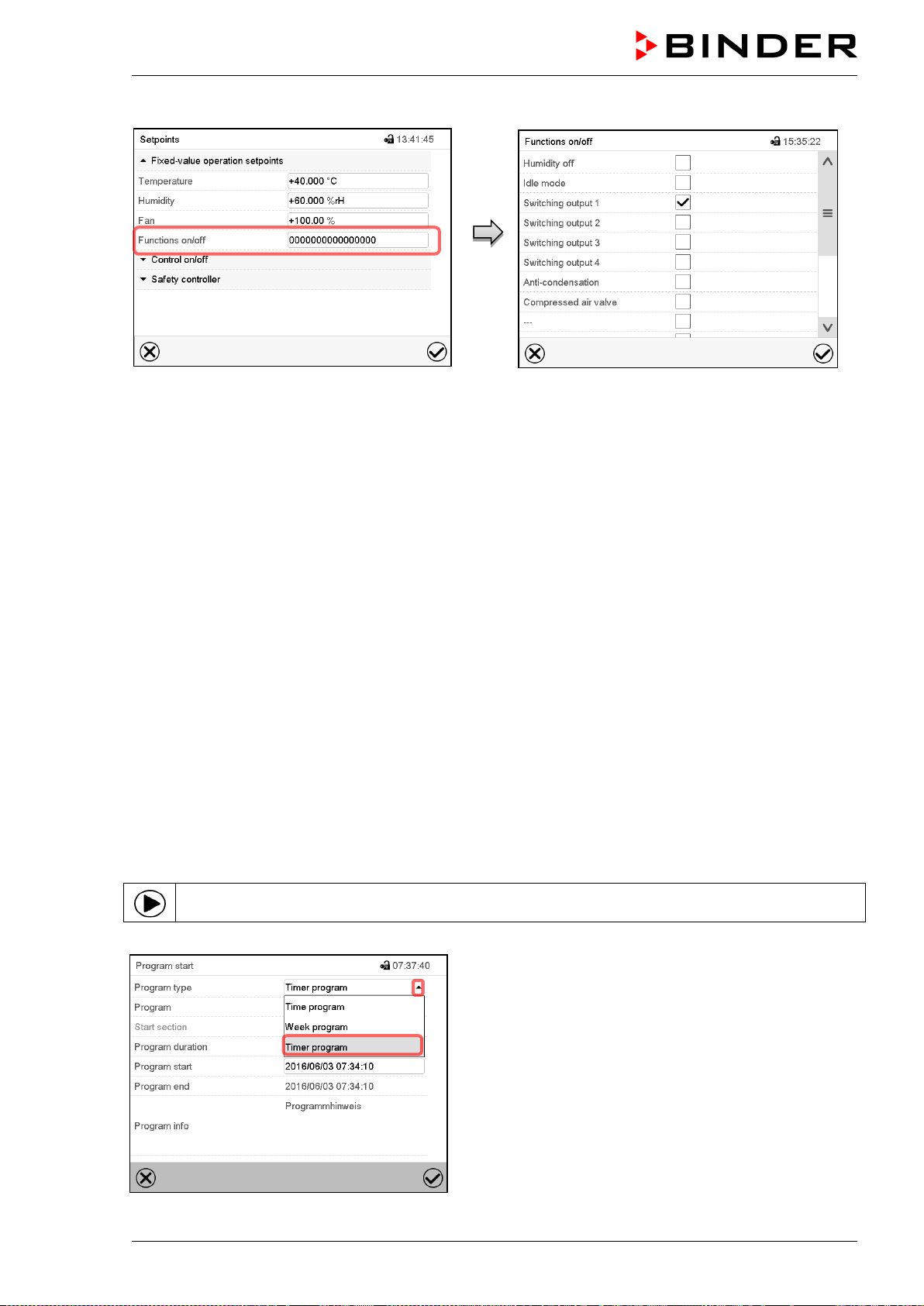
MKF / MKFT (E5) 06/2020 page 55/176
Use the “Setpoints” menu to configure the operation lines.
“Setpoints” menu.
Select the field “Functions on/off”.
“Functions on/off” entry menu (example: MKF
56).
Mark / unmark the checkbox to activate / deacti-
vate the desired function and press the Confirm
icon
Activated operation line: switching status “1” (On)
Deactivated operation line: switching status “0” (Off)
The operation lines count from right to left.
Example:
Activated operation line “Humidity off” = 000000000000000
1
Deactivated operation line “Humidity off” = 000000000000000
0
8. Timer program: stopwatch function
During an entered duration the controller constantly equilibrates to the setpoints entered in Fixed value
operation mode (temperature, humidity, fan speed (with MKF 56), configuration of the operation lines).
This duration can be entered as a “Timer program”. During the program runtime, any setpoint changes do
not become effective; the controller equilibrates to the values which were active during program start.
8.1 Starting a timer program
In Normal display press the Program start icon to access the “Program start” menu.
“Program start” menu
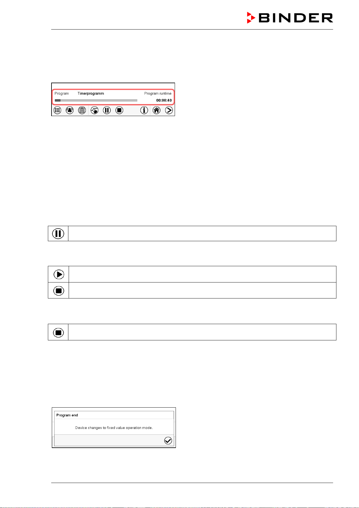
MKF / MKFT (E5) 06/2020 page 56/176
• In the field “Program type” select “Timer program”.
• Select the field “Program duration” and enter the desired program duration. Press the Confirm icon.
• Select the field “Program start” and enter the desired start time of the program in the “Program start”
entry menu. Press the Confirm icon. The program delay time until program start begins.
Normal display.
Information on the bottom of the screen indicates the
currently running program and the time already passed.
The grey bar shows how much time of the whole time is
elapsed.
8.1.1 Performance during program delay time
During the configured program delay time until program start, the controller equilibrates to the current
setpoints of Fixed value operation mode. Modifications of these setpoints are possible but become effec-
tive only after the timer program is finished. When the configured moment for program start is reached,
the program delay time ends and the program starts running. The controller equilibrates to the values
which had been active during program start.
8.2 Stopping a running timer program
8.2.1 Pausing a running timer program
Press the Program pause icon to interrupt the program.
The program is paused. The program runtime stops running down, the time display flashes.
There are the following options:
Press the Program start icon to continue the program
Press the Cancelling icon to cancel the program
8.2.2 Cancelling a running timer program
Press the Program cancelling icon to cancel the program.
A confirmation prompt is displayed. Press the Confirm icon to confirm that the program shall really be
cancelled.
After confirming the message the controller changes to Fixed value operation mode. Temperature and
humidity will then equilibrate to the setpoints of Fixed value operation mode.
8.3 Performance after the end of the program
After the end of the program the message “Device
changes to fixed value operation mode” appears on the
screen.
Press the Confirm icon.
After confirming the message the controller changes to Fixed value operation mode. Temperature and
humidity will then equilibrate to the setpoints of Fixed value operation mode.
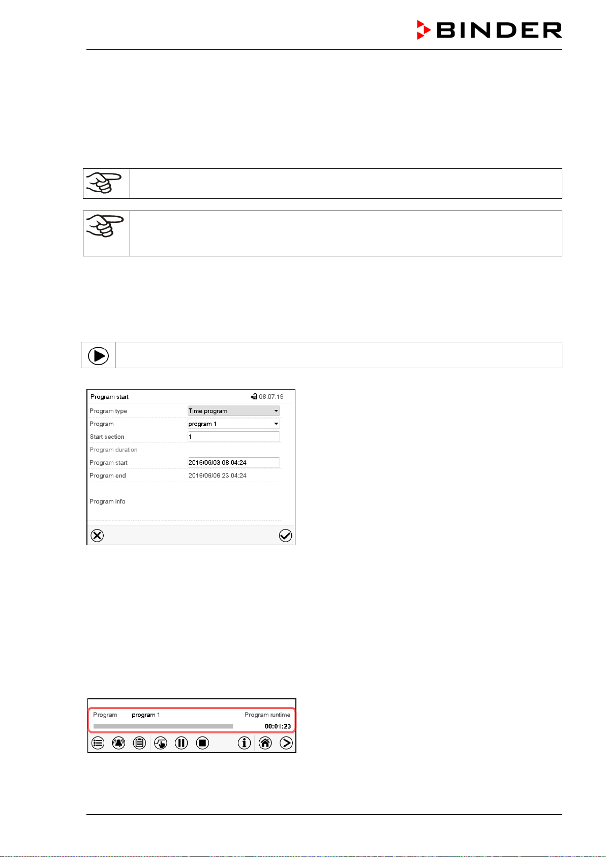
MKF / MKFT (E5) 06/2020 page 57/176
9. Time programs
The MB2 program controller permits programming time programs with real-time reference. It offers 25
program memory positions with up to 100 program sections each.
For each program section you can enter a temperature set-point, the humidity set-point, the fan speed
(MKF 56), section duration, type of temperature and humidity transition (ramp or step) and the tolerance
range.
If the safety controller has been set to “limit” mode, check the setting of the safety controller
when changing the temperature set-point (chap. 12.2).
MKF 56: Reduce the fan speed only if required, because the spatial distribution of tempera-
ture and humidity will also be reduced.
Technical data refers to 100% fan speed.
Programming remains saved in case of a power failure or after turning off the unit.
Path: Main menu > Programs> Time program
9.1 Starting an existing time program
In Normal display press the Program start icon to access the “Program start” menu.
“Program start” menu
• In the field “Program type” select the setting “Time program”.
• In the field “Program” select the desired program.
• Select the field “Program start” and enter the desired program start time in the “Program start” entry
menu. Press the Confirm icon. The program delay time until program start begins.
The program end is adapted automatically depending on the entered program duration.
After completing the settings, press the Confirm icon to take over the entries and exit the menu. The
program starts running.
If instead you press the Close icon to exit the menu without taking over the entries, the program will not
start.
Normal display. Information on the bottom of the
screen indicates the currently running program and the
time already passed. The grey bar shows how much
time of the whole time is elapsed. If program duration
has been set to infinite, the grey bar is not displayed.
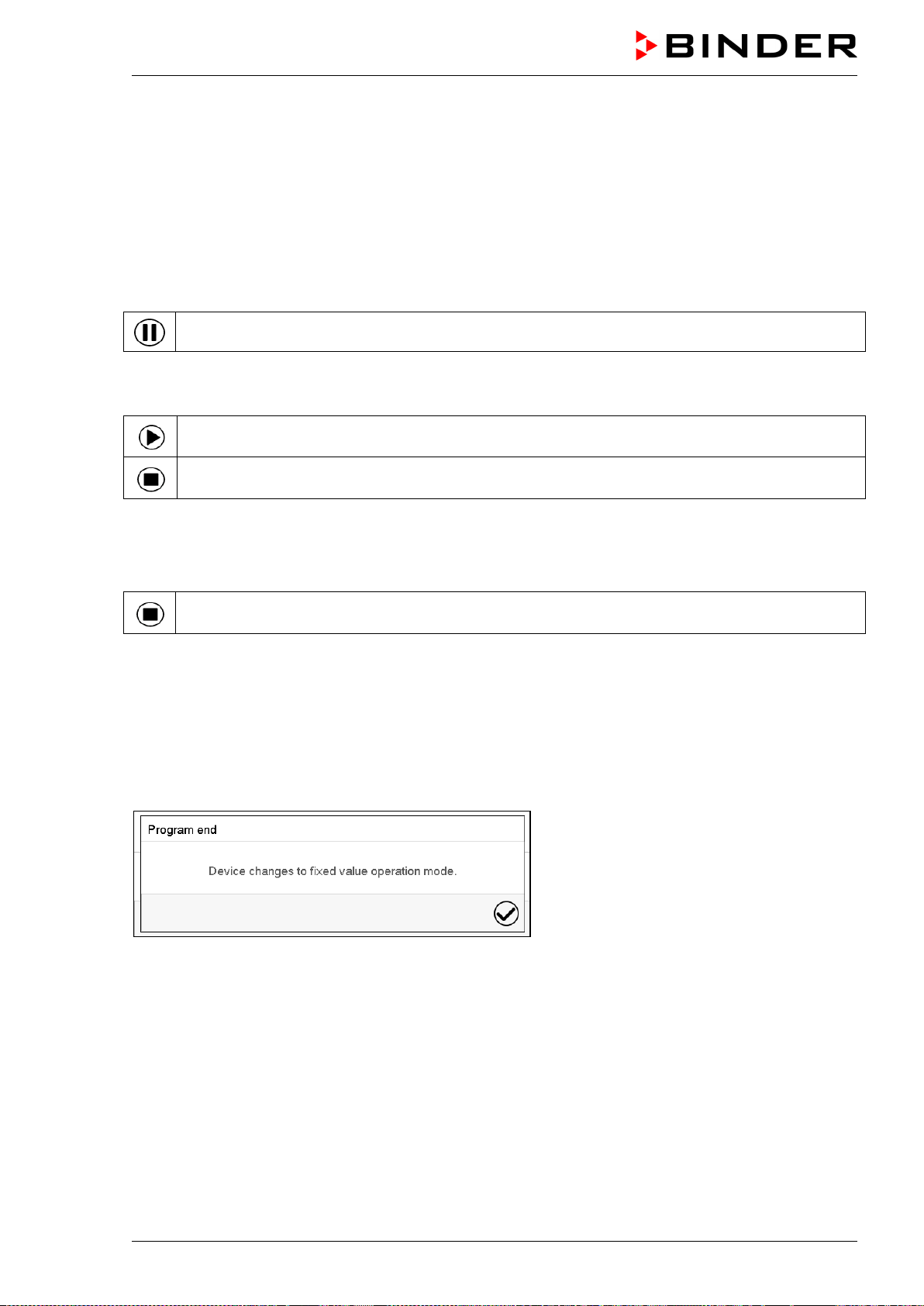
MKF / MKFT (E5) 06/2020 page 58/176
9.1.1 Performance during program delay time
During the configured program delay time until program start, the controller equilibrates to the current
setpoints of Fixed value operation mode. Modifications of these setpoints are effective. When the config-
ured moment for program start is reached, the program delay time ends and the program starts running.
9.2 Stopping a running time program
9.2.1 Pausing a running time program
Press the Program pause icon to interrupt the program.
The program is paused. The program runtime stops running down, the time display flashes.
There are the following options:
Press the Program start icon to continue the program
Press the Cancelling icon to cancel the program
9.2.2 Cancelling a running time program
Press the Program cancelling icon to cancel the program.
A confirmation prompt is displayed. Press the Confirm icon to confirm that the program shall really be
cancelled.
After confirming the message, the controller changes to Fixed value operation mode. Temperature and
humidity will then equilibrate to the setpoints of Fixed value operation mode.
9.3 Performance after the end of the program
After the end of the program the message
“Device changes to fixed value operation
mode” appears on the screen.
Press the Confirm icon.
As long as the message has not been confirmed, the setpoint of the last program section remains effec-
tive. Program the last section as desired. If e.g. heating, refrigeration, humidification an dehumidification
shall turn off, activate operation line “Idle mode” in the last program section.
After confirming the message the controller changes to Fixed value operation mode. Temperature and
humidity will then equilibrate to the setpoints of Fixed value operation mode.
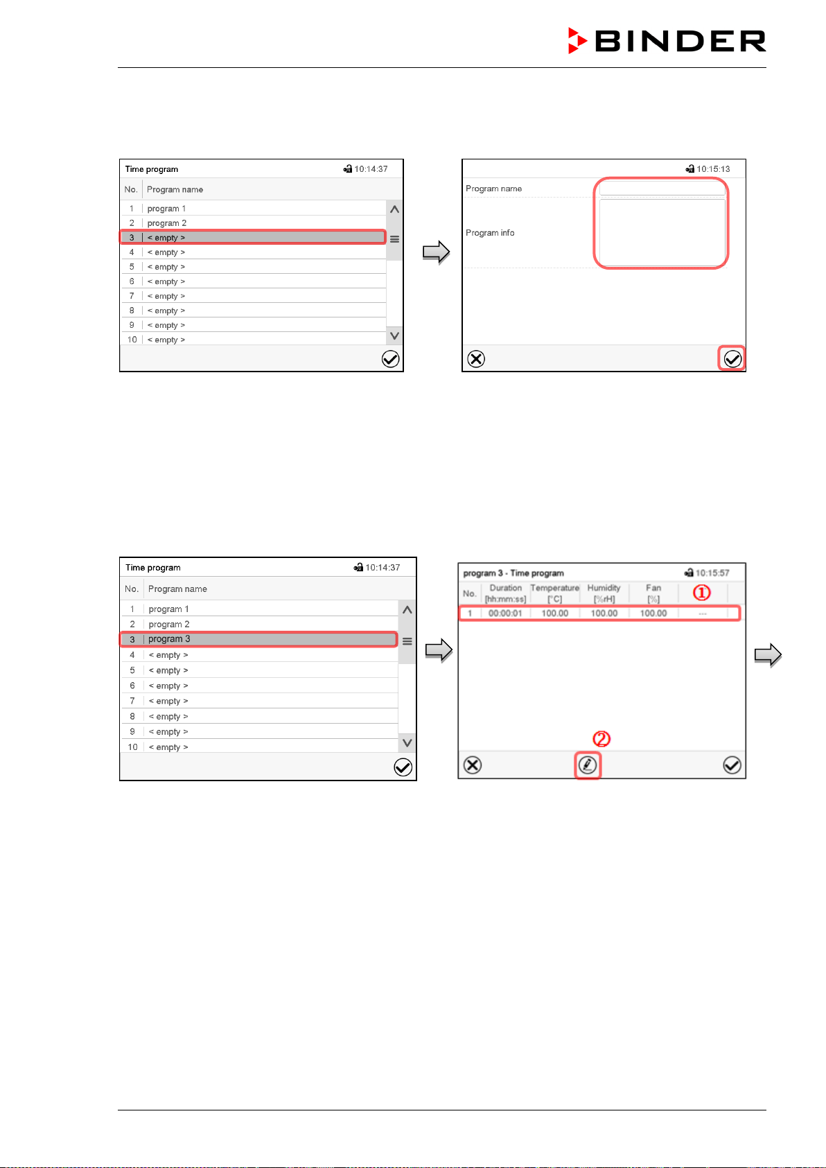
MKF / MKFT (E5) 06/2020 page 59/176
9.4 Creating a new time program
Path: Main menu > Programs > Time program
“Time program” menu:
overview of the existing programs.
Select an empty program place.
Enter the program name and, if desired, addi-
tional program information in the corresponding
fields.
Press the Confirm icon.
The program view opens (chap. 9.5).
9.5 Program editor: program management
Path: Main menu > Programs > Time program
“Time program” menu:
overview of the existing programs.
Select an existing program (example: program
3) or create a new program (chap. 9.4).
The program view opens.
Program view (example: program 3).
If a new program has been created, there is
just one program section.
There are the following options:
Select a program section to open the
section editor (chap. 9.6)
Press the Edit icon to open the program
editor
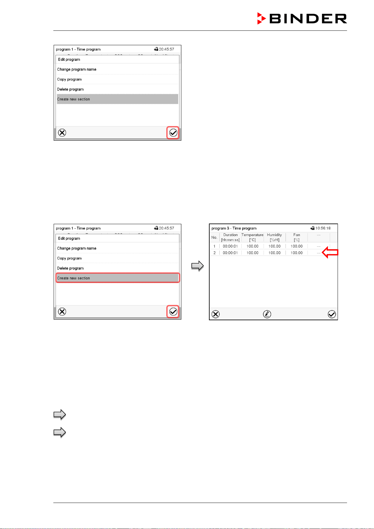
MKF / MKFT (E5) 06/2020 page 60/176
Program editor: “Edit program” menu
Select the desired function and press the Confirm
icon.
The program editor offers following options:
• Change the program name
• Copy program
• Replace program: Replacing an new or an existing program with the copied program. This menu point
is visible only after a program has been copied.
• Delete program
• Create new section
To add a new section, select “Create new sec-
tion” and press the Confirm icon.
The program view opens.
Program view.
A new section is always added at the very bot-
tom (example: section 2).
9.5.1 Deleting a time program
Path: Main menu > Programs > Time program
In the “Time program” menu select the program to be deleted. The program view opens.
In the program view press the Edit icon to open the program editor
In the program editor select “Delete program” and press the Confirm icon.
The program is deleted. The controller returns to the program view.
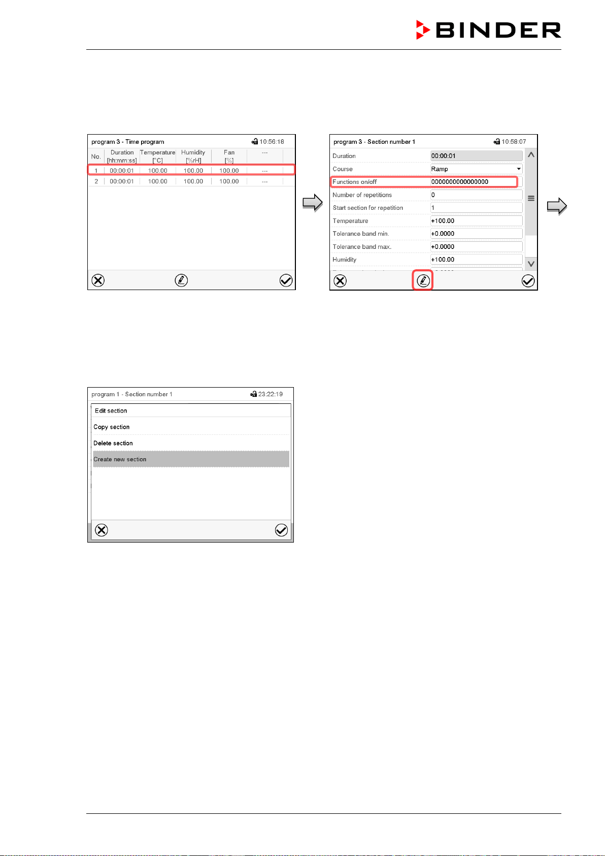
MKF / MKFT (E5) 06/2020 page 61/176
9.6 Section editor: section management
Path: Main menu > Programs > Time program
Select the desired program.
Program view.
Select the desired program section
(example: section 1)
Section view (example: section 1).
There are the following options:
Select a parameter to enter or modify the
according value (chap. 9.7)
Press the Edit icon to open the program
editor
Section editor: “Edit section” menu
Select the desired function and press the Confirm icon.
The section editor offers following options:
• Copy section
• Replace section: Replacing an existing section with the copied section. This menu point is visible only
after a section has been copied.
• Insert section: Adding the copied section. This menu point is visible only after a section has been cop-
ied.
• Delete section
• Create new section
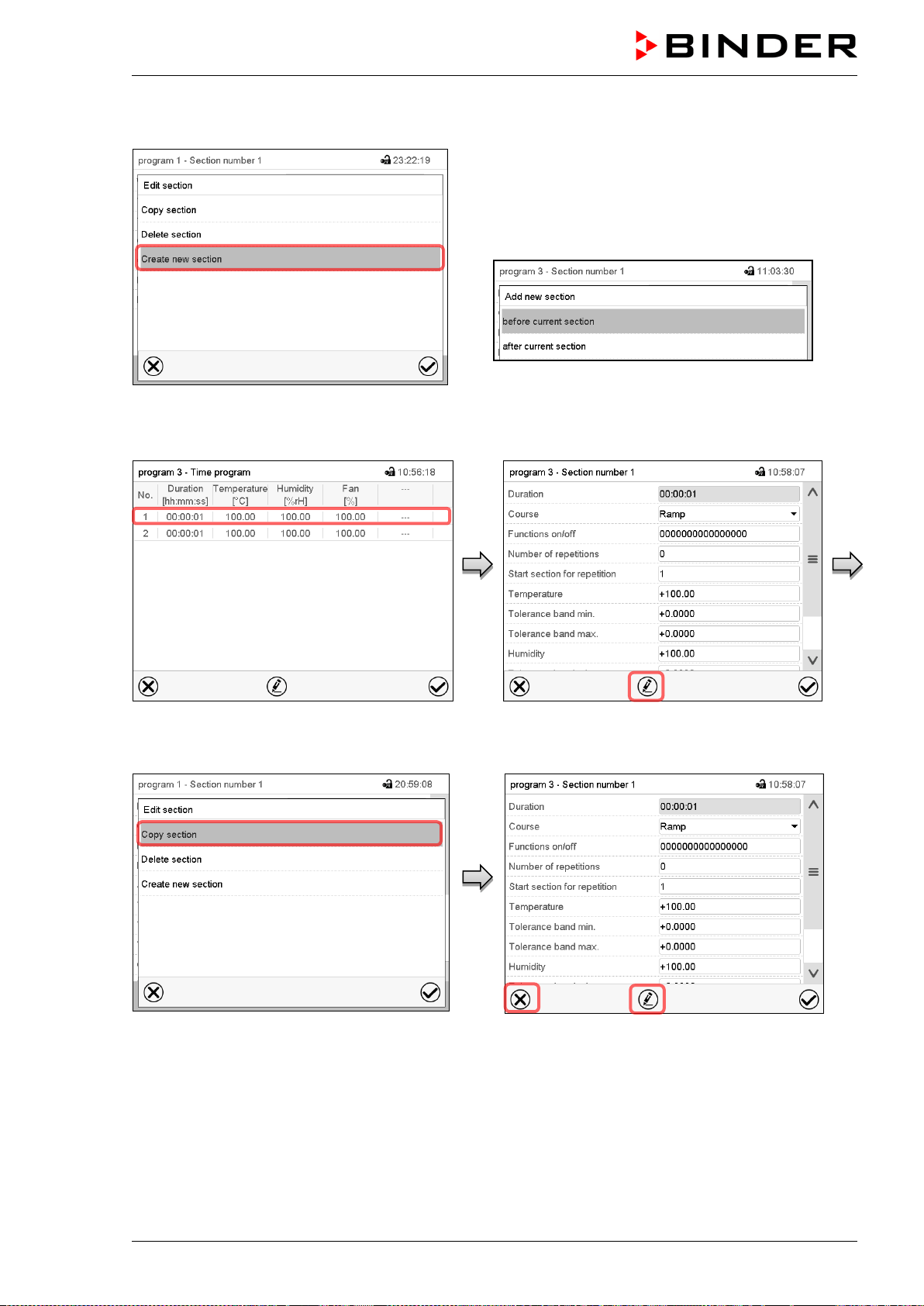
MKF / MKFT (E5) 06/2020 page 62/176
9.6.1 Add a new program section
Section editor: “Edit section” menu.
Select “Create new section” and press the Con-
firm icon.
Then select whether to insert the new section
before or after the current section.
Press the Confirm icon. The new section opens.
9.6.2 Copy and insert or replace a program section
Program view.
Select the program section to be copied
(example: section 1)
Section view (example: section 1).
Press the Edit icon to open the section editor.
Section editor: “Edit section” menu
Select “Copy section” and press the Confirm
icon.
The current section (example: section 1) is
copied.
The controller returns to the section view.
Section view (example: section 1).
Press the Close icon to change to the pro-
gram view, if you want to select another sec-
tion to be replaced or before or after which the
copied section shall be inserted…
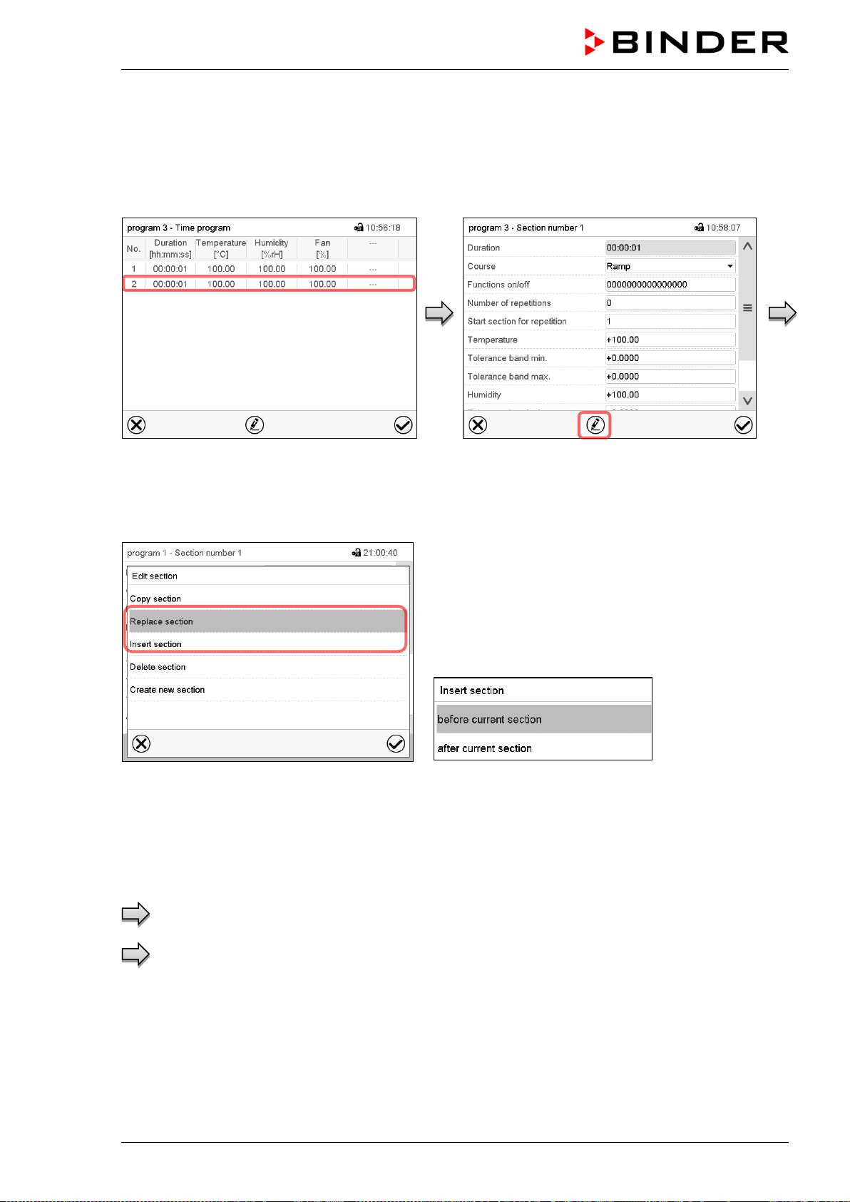
MKF / MKFT (E5) 06/2020 page 63/176
or
Press the Edit icon to open the section editor if
you want the current section to be replaced or
the copied section to be inserted before or
after it
Program view.
Select the section to be replaced or before or
after which the copied section shall be insert-
ed (example: section 2) and press the Con-
firm icon.
Section view (example: section 1).
Press the Edit icon to open the section editor
Section editor: “Edit section” menu
Select “Replace section” to replace the selected sec-
tion with the copied section
or
Select “Insert section” to additionally add the copied
section.
In this case select whether to insert it before or after
the selected section.
Press the Confirm icon
9.6.3 Deleting a program section
In the program view select the program section to be deleted. The section view opens.
In the section view press the Edit icon to open the section editor
In the section editor select “Delete section” and press the Confirm icon.
The section is deleted. The controller returns to the section view.
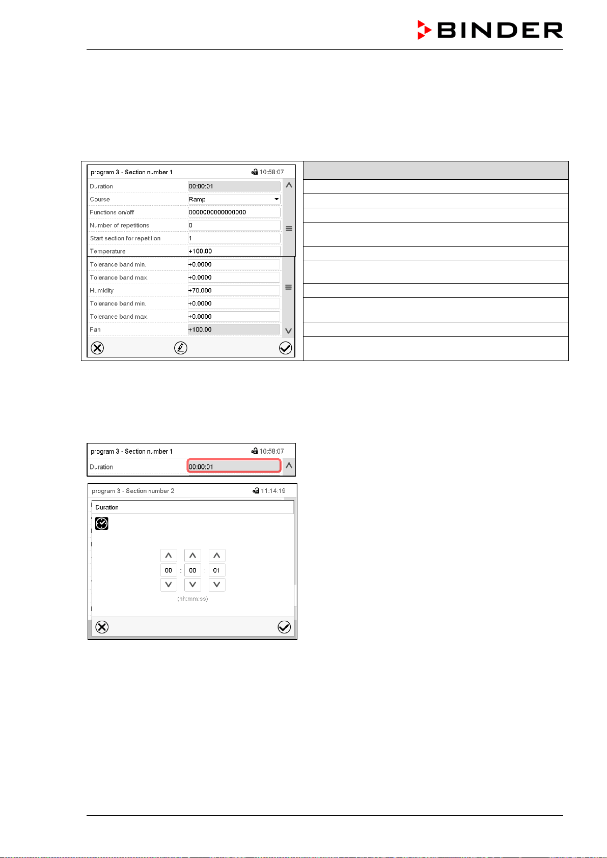
MKF / MKFT (E5) 06/2020 page 64/176
9.7 Value entry for a program section
Path: Main menu > Programs > Time program
Select the desired program and section.
The section view gives access to all parameters of a program section. You can enter or modify the val-
ues.
Program name and section number
Section duration
Type of setpoint transition: ramp or step
Operation lines
Repeating one or several sections within a program
Temperature setpoint
Temperature tolerance range: minimum and maximum
Humidity setpoint
Humidity tolerance range: minimum and maximum
Fan speed (MKF 56)
The setting and control ranges for the individual parameters are the same as for “Fixed value” operating
mode (chap. 7).
9.7.1 Section duration
Section view (partial view).
Select the field “Duration” indicating the time.
“Duration” entry menu.
Enter the desired section duration with the arrow keys
and press the Confirm icon.
Setting range: 0 up to 99 hours 59 min 59 sec.
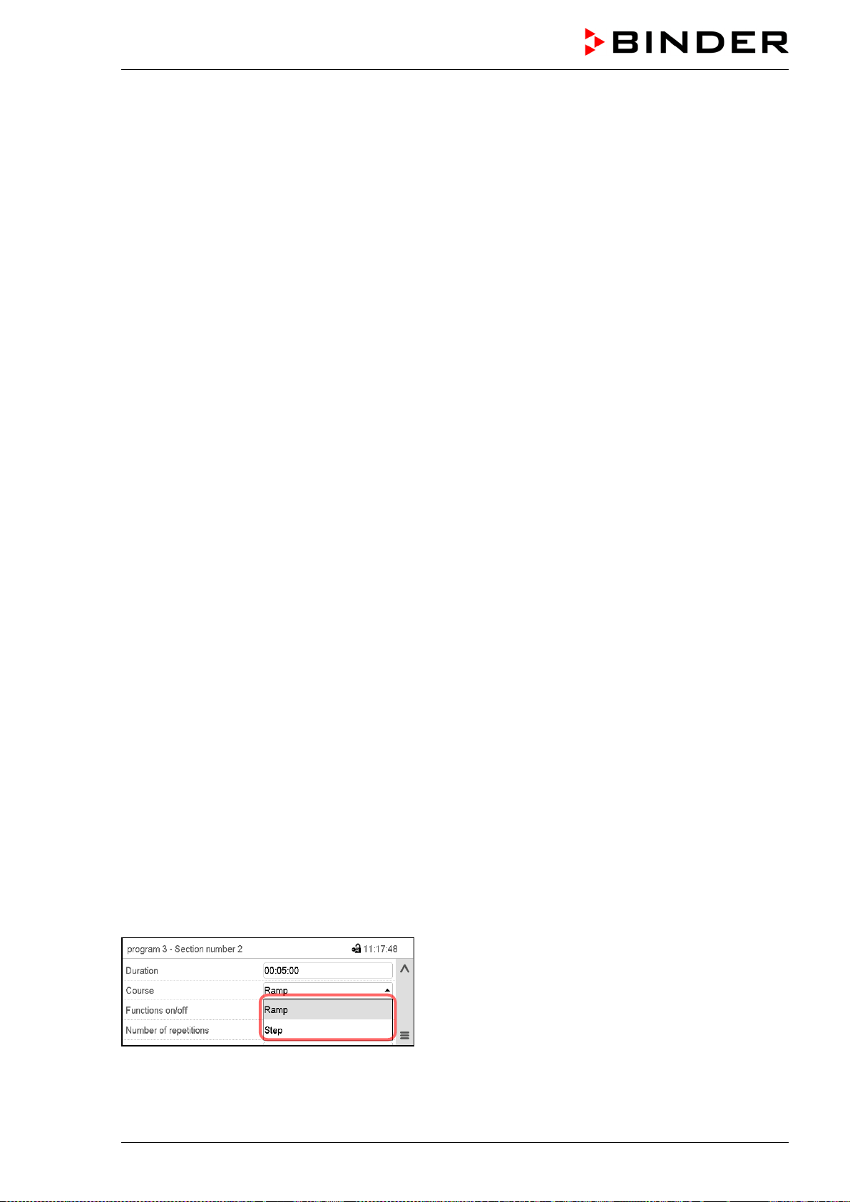
MKF / MKFT (E5) 06/2020 page 65/176
9.7.2 Set-point ramp and set-point step
You can define the type of temperature and humidity transitions for each individual program section.
“Ramp” mode: Gradual changes of temperature and humidity
The set-point of a given program section functions as the section’s start temperature. During the section’s
duration, the set-point gradually passes to the set-point of the subsequent program section. The actual
value follows the continually changing set-point.
If the last program section is in “ramp” mode and the setpoint shall change within this section, then you
must program an additional section (with the shortest possible section duration) to provide the target tem-
perature of the last program section. Otherwise, the setpoint would remain constant during the section’s
duration.
Programming in the “ramp” mode allows all kinds of temperature and humidity transitions:
• Gradual changes of temperature and humidity
The setpoint changes its value gradually during the entered section duration. The actual value follows
the continually moving set-point at any time.
• Program sections with constant temperature and humidity
The setpoints (initial values) of two subsequent program sections are identical; so the temperature and
humidity remain constant during the entire duration of the first program section.
• Sudden changes of temperature and humidity
Steps can be programmed in ramp mode as temperature or humidity changes (ramps) that occur dur-
ing a very short interval. If the duration of this transitional program section is very short (minimum entry
1 sec), the temperature or humidity change will proceed rapidly within the minimum amount of time.
“Step” mode: Sudden changes of temperature and humidity
The set-point of any program section functions as the section’s target value. At the start of the program
section, the unit heats up or cools down and humidifies/dehumidifies the chamber with the maximum
speed to reach the entered value; and then it holds it for the remaining section time. Therefore the set-
point temperature remains constant for the section’s duration. These changes occur rapidly within the
minimum amount of time (minimum entry: 1 second).
Programming in the “step” mode allows only two kinds of temperature and humidity transitions:
• Programming gradual changes of temperature and humidity (ramps) is impossible in the “step” mode
• Program sections with constant temperature and humidity
The setpoints (target values) of two subsequent program sections are identical; so the temperature
and humidity remain constant during the entire duration of the first program section.
• Sudden changes of temperature and humidity
The entered setpoint of the section is reached as fast as possible and then held constant for the re-
maining section duration.
Selecting the setting “Ramp” or “Step”
Section view (partial view).
In the field “Course” select the desired setting
“Ramp” or “Step”.
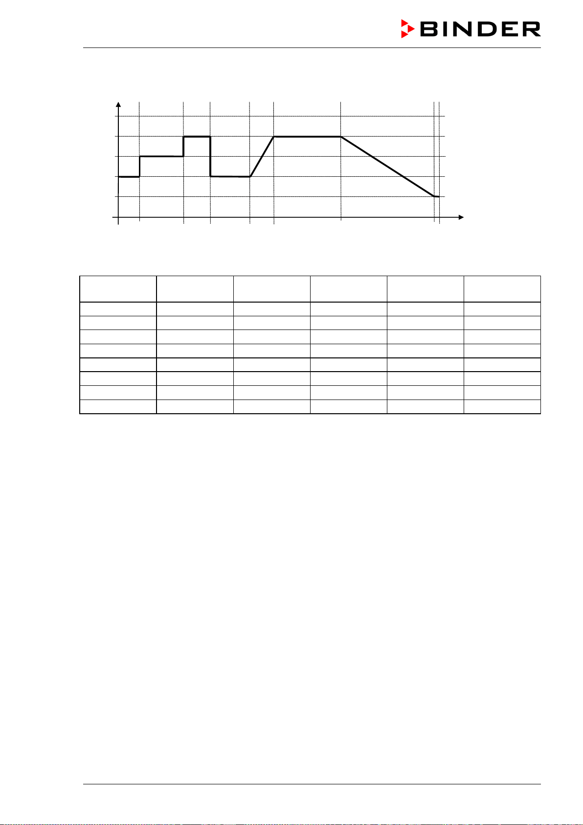
MKF / MKFT (E5) 06/2020 page 66/176
“Ramp” and “Step” mode example (representation of a temperature course)
W/°C
t/min.
0
20
40
60
80
100
10 30 40 60 70 100 130
1 2
3 4 5 6 7
8
Corresponding program table
Section No.
Duration
[hh:mm:ss]
Temperature
[°C]
Humidity
[% rH]
Fan (MKF 56)
[%]
Ramp or Step
1
00:10:00
40.0
xxxx
xxxx
Step
2
00:20:00
60.0
xxxx
xxxx
Step
3
00:10:00
80.0
xxxx
xxxx
Step
4
00:20:00
40.0
xxxx
xxxx
Step
5
00:10:00
40.0
xxxx
xxxx
Ramp
6
00:30:00
80.0
xxxx
xxxx
Ramp
7
00:30:00
80.0
xxxx
xxxx
Ramp
8
00:00:01
20.0
xxxx
xxxx
Ramp
9.7.3 Special controller functions via operation lines
You can define the switching state of up to 16 operation lines (control contacts). They are used to activate
/ deactivate special controller functions.
• Operation line “Humidity off” serves to turn off the humidity.
• Operation line Idle mode” activates / deactivates the operating mode “Idle mode”.
• Operation lines “Switching output 1” up to “4” can be used to turn on and off any equipment connected
to the zero-voltage switching outputs (DIN sockets (7) and (8) (chap. 20).
• Operation line “Compr. air dryer” serves to activate the compressed air dryer (option, chap. 21.6).
• Operation line “Compressed air valve” serves to open the solenoid valve of the compressed air con-
nection (for options compressed air connection, chap. 21.5, or compressed air dryer, chap. 21.6)
• Operation line “Anti-condensation” serves to switch the anti-condensation protection (chap. 19).
The other operation lines are without function.
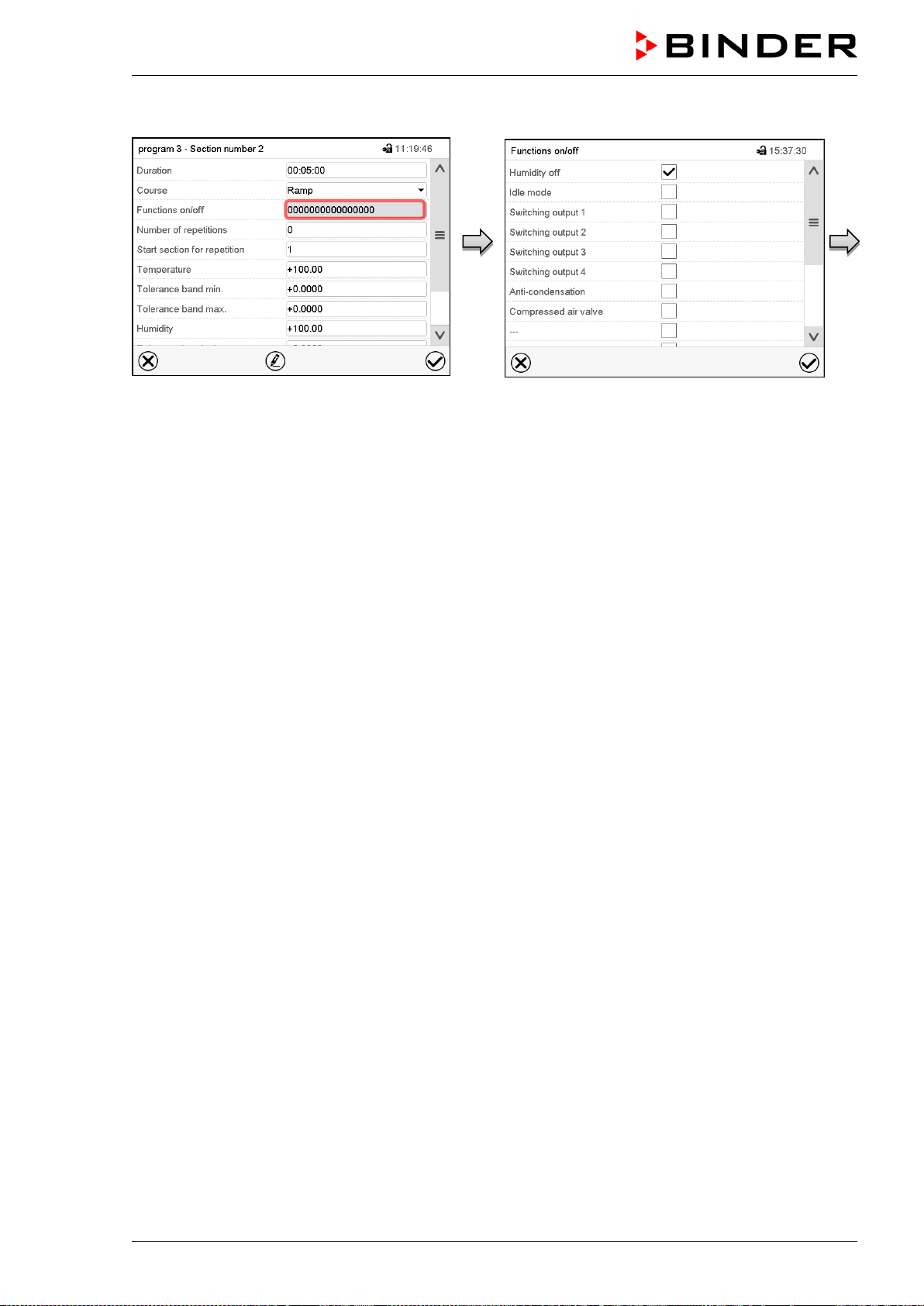
MKF / MKFT (E5) 06/2020 page 67/176
Use the Section editor to configure the operation lines.
Section view.
Select the field “Functions on/off”.
“Functions on/off” entry menu.
Mark / unmark the checkbox of the desired
function to activate / deactivate it and press
the Confirm icon.
The controller returns to the section view.
Activated operation line: switching status “1” (On)
Deactivated operation line: switching status “0” (Off)
The operation lines count from right to left.
Example:
Activated operation line “Humidity off” = 000000000000000
1
Deactivated operation line “Humidity off” = 000000000000000
0
9.7.4 Setpoint entry
• Select the field “Temperature” and enter the desired temperature setpoint.
Setting range: MKF: -50 °C up to 180 °C, MKFT: -80 °C up to 180 °C.
Confirm entry with Confirm icon. The controller returns to the section view.
• Select the field “Humidity” and enter the desired humidity setpoint.
Setting range: 0% r.h. up to 100% r.h.
Confirm entry with Confirm icon. The controller returns to the section view.
• MKF 56: Select the field “Fan” and enter the desired fan speed setpoint.
Setting range: 30% up to 100% fan speed.
Confirm entry with Confirm icon. The controller returns to the section view.
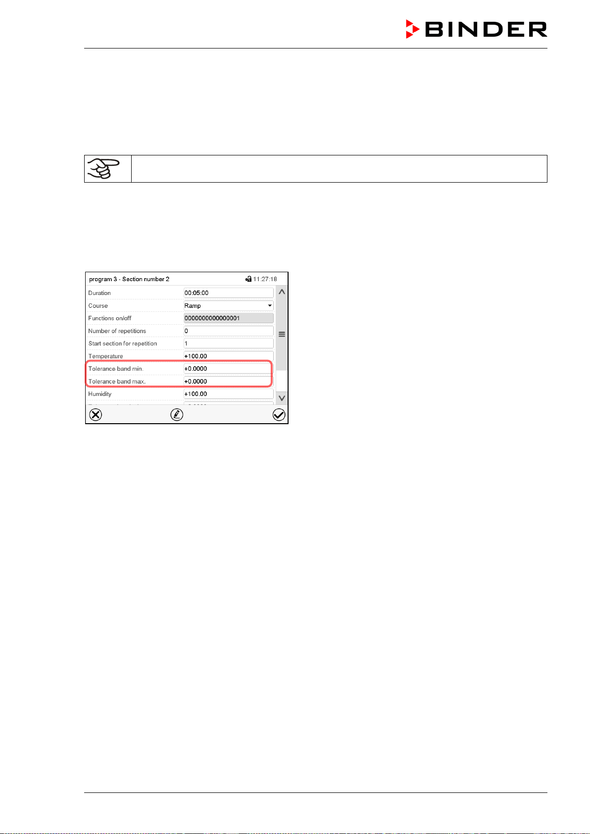
MKF / MKFT (E5) 06/2020 page 68/176
9.7.5 Tolerance range
You can specify a temperature and humidity program tolerance range for each program section with dif-
ferent values for the tolerance minimum and maximum. When the actual value exceeds the given thresh-
old, the program is interrupted. This is indicated on the display (see below). When the actual temperature
is situated again within the entered tolerance limits, the program automatically continues. Therefore, the
duration of the program may be extended due to the programming of tolerances.
Programming of tolerances may extend program duration.
An entry of “-99999” for the tolerance minimum means “minus infinite” and an entry of “999999” for the
tolerance maximum means “plus infinite”. Entry of these values will never lead to program interruption.
The entry of “0” for the tolerance minimum and/or maximum deactivates the respective tolerance function.
When requesting rapid value transitions, we recommend not programming tolerance values in order to
enable the maximum heating-up, cooling-down, humidification or dehumidification speed.
Section view, showing the temperature tolerance
band
• Select the field “Tolerance band min” and enter the desired lower tolerance band value. Setting range:
-99999 to 99999. Confirm entry with Confirm icon. The controller returns to the section view.
• Select the field “Tolerance band max” and enter the desired upper tolerance band value. Setting
range: -99999 to 99999. Confirm entry with Confirm icon. The controller returns to the section view.
Set the tolerance ranges for other parameters accordingly, if desired.
If one of the actual values (temperature and/or humidity) is outside the program tolerance range the
whole program course is interrupted. During this program interruption time the controller equilibrates to
the set-points of the current section.
The screen header indicates “Program pause (tolerance band)”. The program runtime indication flashes
and does not proceed any further.
When the temperature or humidity values are back within the entered program tolerance range, the pro-
gram continues automatically.
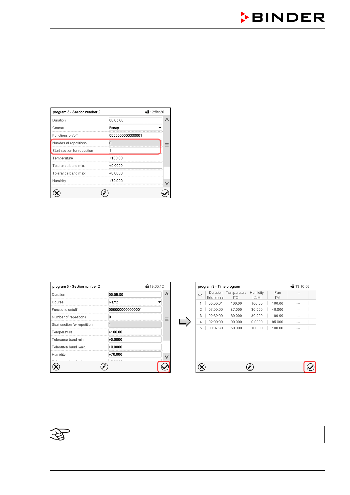
MKF / MKFT (E5) 06/2020 page 69/176
9.7.6 Repeating one or several sections within a time program
You can repeat several subsequent sections together. It is not possible to define the start section the
same time also as the target section, therefore you cannot repeat a single individual section.
Enter the desired number of repetitions in the field „Number of repetitions“ and the number of the section
to start the repetition cycle with in the field “Start section for repetition” To have sections repeated infinite-
ly, enter the number of repetitions as “-1”.
The selected sections are repeated as many times as selected. Then the program continues.
Section view, showing the repetition function.
• Select the field “Number of repetitions” and enter the desired number of repetitions. Setting range: 1 to
99, and -1 for infinite. Confirm entry with Confirm icon. The controller returns to the section view.
• Select the field “Start section for repetition” and enter the section number, at which the repetition
should start. Setting range: 1 up to the section before the currently selected section. Confirm entry
with Confirm icon. The controller returns to the section view.
9.7.7 Saving the time program
Section view.
After the all desired values of the program
section have been configured, press the Con-
firm icon to take over the programming.
The controller changes to the program view.
Program view.
Press the Confirm icon to take over the pro-
gramming.
The controller changes to the Normal display.
To save the programming it is absolutely required to press the Confirm icon. Otherwise all
settings will be lost! There is no confirmation prompt!
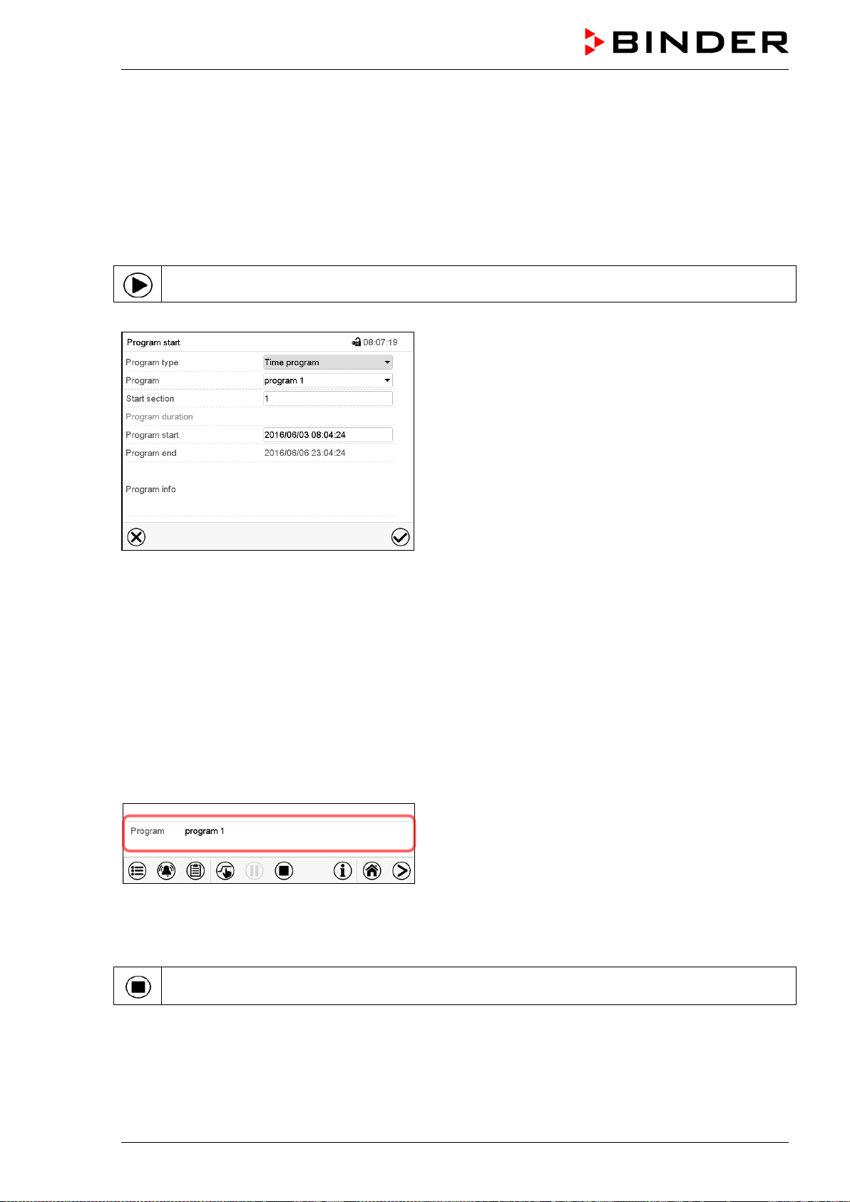
MKF / MKFT (E5) 06/2020 page 70/176
10. Week programs
The MB2 program controller permits programming week programs with real-time reference. It offers 5
week program places in total with up to 100 shift points for each week program.
Path: Main menu > Programs> Week program
10.1 Starting an existing week program
In Normal display press the Program start icon to access the “Program start” menu.
“Program start” menu.
• In the field “Program type” select the setting “Week program”.
• In the field “Program” select the desired program.
• There are no further settings available in the “Program start” menu for week programs, as they are
needed only for time programs.
After completing the settings, press the Confirm icon to take over the entries and exit the menu. The
program starts running.
If instead you press the Close icon to exit the menu without taking over the entries, the program will not
start.
After starting the week program, the previously entered week program setpoints are active and will be
equilibrated according to the current time.
Information on the bottom of the screen indicates the
currently running program.
10.2 Cancelling a running week program
Press the Program cancelling icon to cancel the program.
A confirmation prompt is displayed. Press the Confirm icon to confirm that the program shall really be
cancelled.
After confirming the message the controller changes to Fixed value operation mode. Temperature and
humidity will then equilibrate to the setpoints of Fixed value operation mode.
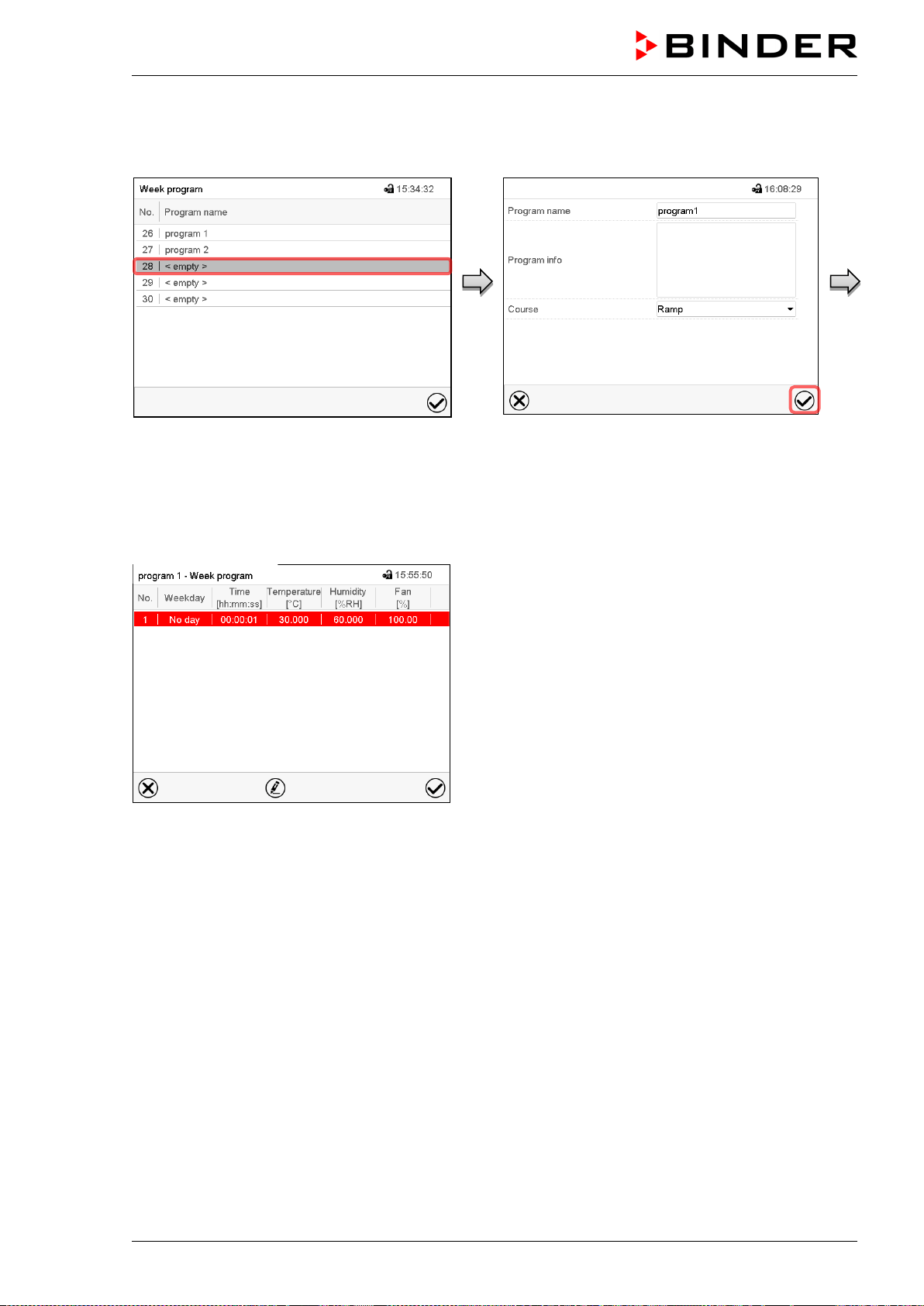
MKF / MKFT (E5) 06/2020 page 71/176
10.3 Creating a new week program
Path: Main menu > Programs > Week program
“Week program” menu:
overview of the existing programs.
Select an empty program place.
Enter the program name and, if desired, addi-
tional program information in the correspond-
ing fields.
Select the set-point course “Ramp” or “Step”
(chap. 10.6.1).
Press the Confirm icon. The program view
opens.
Program view.
For the first section no weekday is specified.
Therefore the section is first marked in red and
cannot be saved.
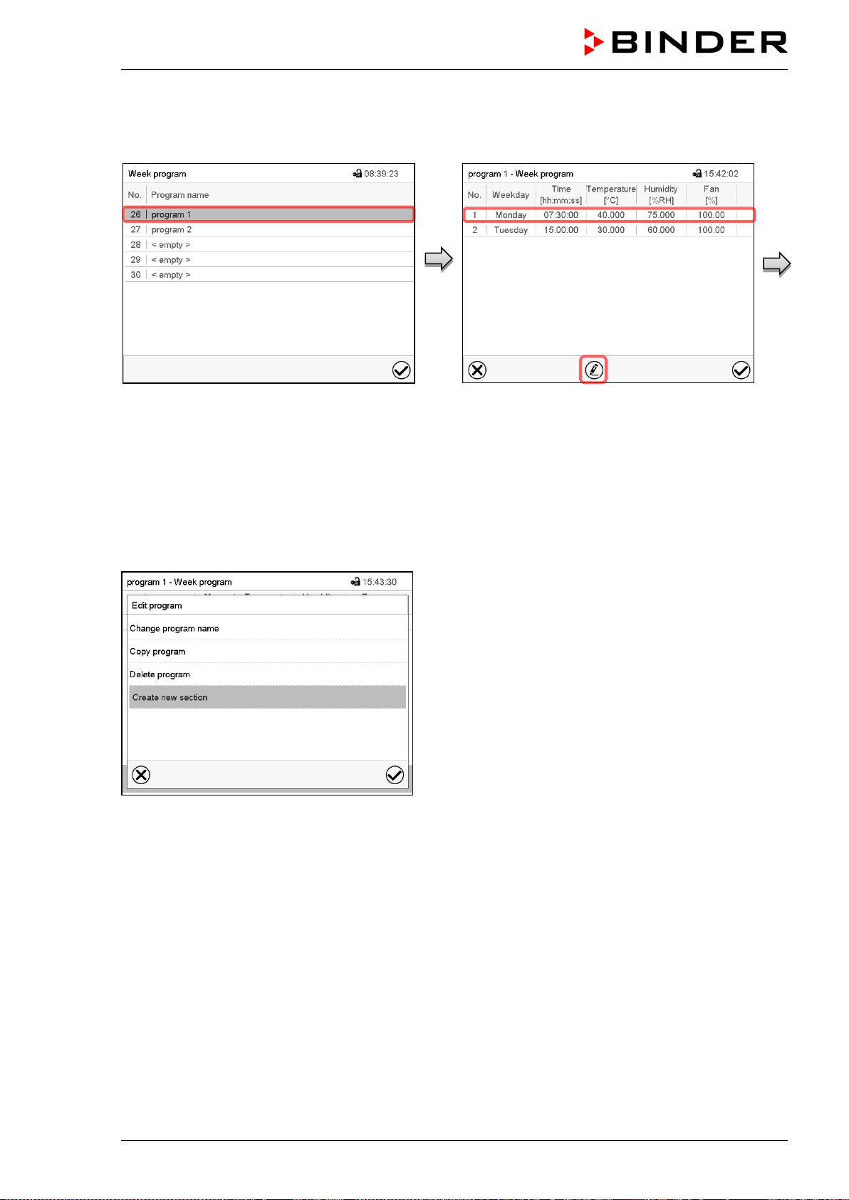
MKF / MKFT (E5) 06/2020 page 72/176
10.4 Program editor: program management
Path: Main menu > Programs > Week program
“Week program” menu:
overview of the existing programs.
Select an existing program
(example: program 1).
Program view (example: program 1).
If a new program has been created, there is
just one program section.
There are the following options:
Select a program section to open the
section editor (chap. 10.5)
Press the Edit icon to open the program
editor
Program editor: “Edit program” menu.
Select the desired function and press the Confirm icon.
The program editor offers following options:
• Change program name. This menu also offers to configure the ramp / step mode setting (chap.
10.6.1).
• Copy program
• Replace program: Replacing an new or an existing program with the copied program. This menu point
is visible only after a section has been copied.
• Delete program
• Create new section
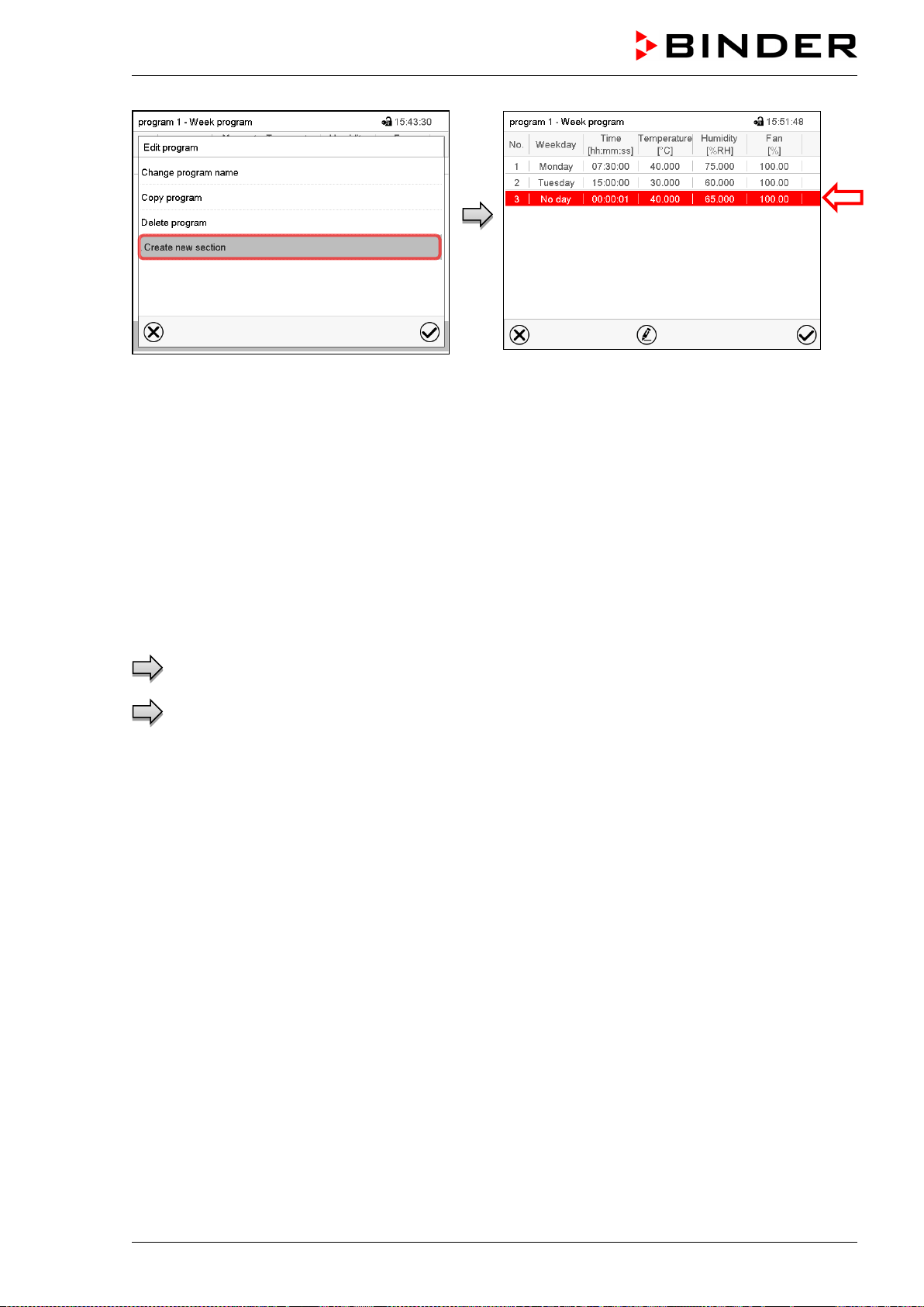
MKF / MKFT (E5) 06/2020 page 73/176
To add a new section, select “Create new
section” and press the Confirm icon.
The program view opens.
Program view.
With a new section no weekday is specified. There-
fore the section is first marked in red and cannot be
saved.
A new section is always added at the very bottom
(example: section 3). When the section start is
specified the sections are automatically arranged in
the correct chronological order.
10.4.1 Deleting a week program
Path: Main menu > Programs > Week program
In the “Week program” menu select the program to be deleted. The program view opens.
In the program view press the Edit icon to open the program editor
In the program editor select “Delete program” and press the Confirm icon.
The program is deleted. The controller returns to the program view.
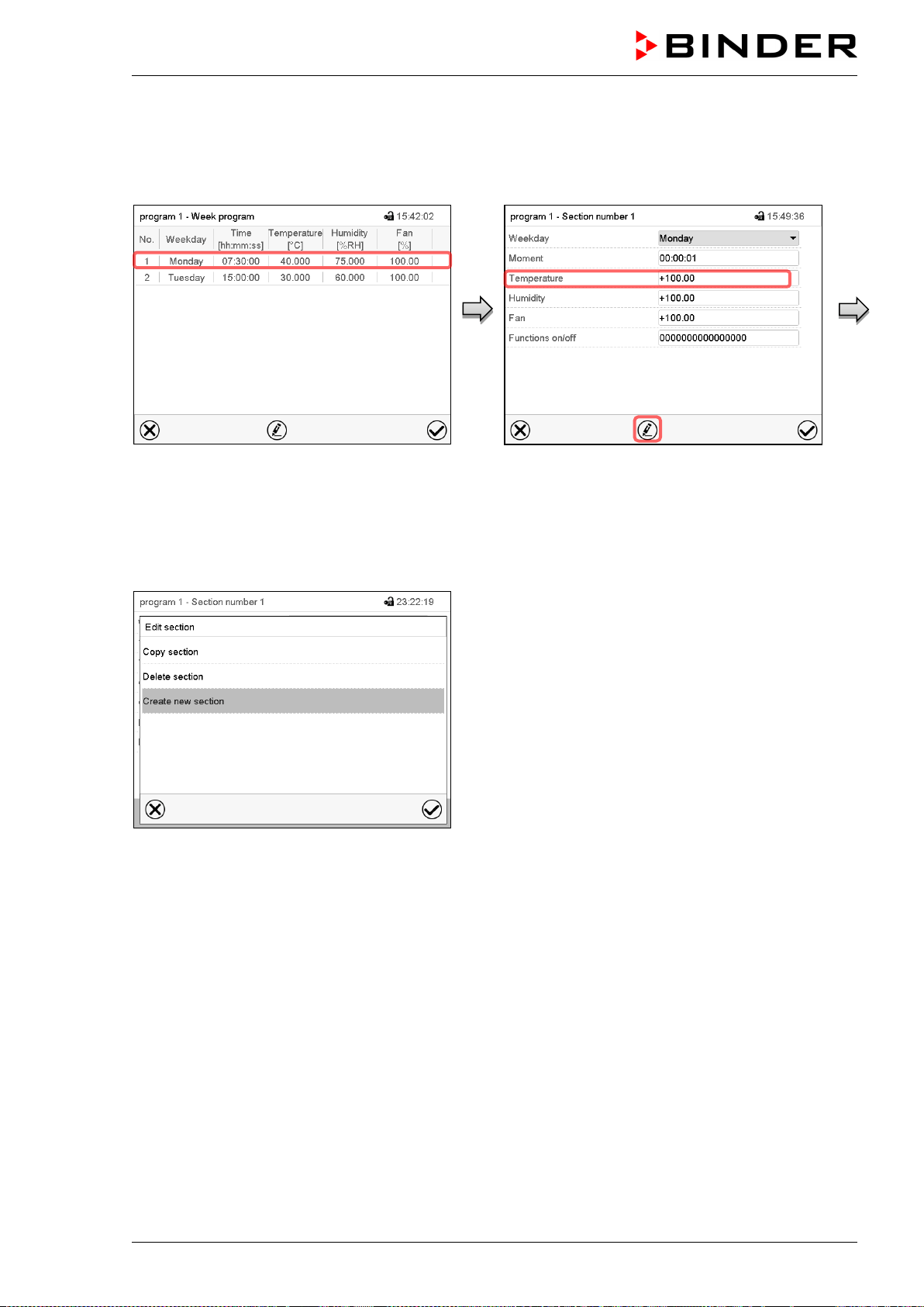
MKF / MKFT (E5) 06/2020 page 74/176
10.5 Section editor: section management
Path: Main menu > Programs > Week program
Select the desired program.
Program view.
Select the desired program section
(example: section 1)
Section view (example: section 1).
There are the following options:
Select a parameter to enter or modify the
according value (chap. 10.6)
Press the Edit icon to open the program
editor
Section editor: “Edit section” menu
Select the desired function and press the Confirm icon.
The section editor offers following options:
• Copy section
• Replace section: Replacing an existing section with the copied section. This menu point is visible only
after a section has been copied.
• Insert section: Adding the copied section. This menu point is visible only after a section has been cop-
ied.
• Delete section
• Create new section
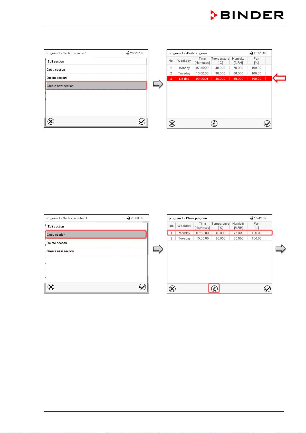
MKF / MKFT (E5) 06/2020 page 75/176
10.5.1 Add a new program section
Section editor: “Edit section” menu.
Select “Create new section” and press the
Confirm icon.
Program view.
With a new section no weekday is specified. There-
fore the section is first marked in red and cannot be
saved.
A new section is always added at the very bottom
(example: section 3). When the section start is speci-
fied the sections are automatically arranged in the
correct chronological order.
10.5.2 Copy and insert or replace a program section
Section editor: “Edit section” menu
Select “Copy section” and press the Confirm
icon.
The current section (example: section 1) is
copied.
The controller returns to the program view.
Program view
Select the section to be replaced or before or
after which the copied section shall be insert-
ed (example: section 2).
Press the Confirm icon
The controller returns to the section editor
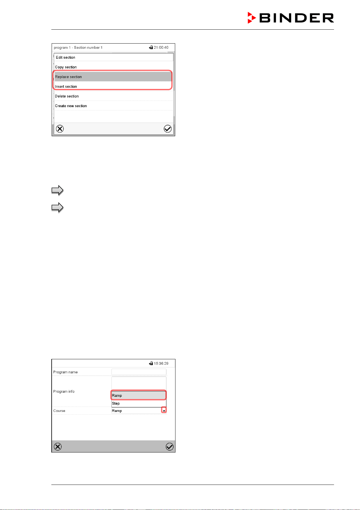
MKF / MKFT (E5) 06/2020 page 76/176
Section editor: “Edit section” menu
Select “Replace section” to replace the selected sec-
tion with the copied section
or
Select “Insert section” to additionally add the copied
section.
Press the Confirm icon.
If you selected “Insert section” the sections are auto-
matically arranged in the correct chronological order.
10.5.3 Deleting a program section
In the program view select the program section to be deleted. The section view opens.
In the section view press the Edit icon to open the section editor
In the section editor select “Delete section” and press the Confirm icon.
The section is deleted. The controller returns to the section view.
10.6 Value entry for a program section
Path: Main menu > Programs > Week program
Select the desired program and section.
The setting and control ranges for the individual parameters are the same as for “Fixed value” operating
mode (chap. 7).
10.6.1 Set-point ramp and set-point step modes
The explanation of the settings “Ramp” or “Step” is given in chap. 9.7.2.
You can define the type of temperature and humidity transitions for the entire week program.
Select the desired program and press the Edit icon to open the program editor. In the program editor
select the “Change program name” function and press the Confirm icon.
“Change program name” menu.
In the field “Course” select the desired setting “Ramp”
or “Step” and press the Confirm icon.
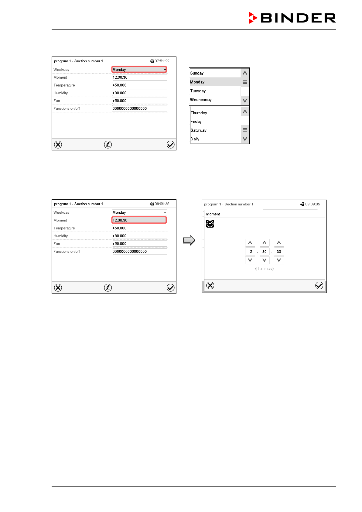
MKF / MKFT (E5) 06/2020 page 77/176
10.6.2 Weekday
Section view.
In the field “Weekday” select the desired weekday.
With “Daily” selected, this section will run every day
at the same time.
10.6.3 Start time
Section view.
Select the field “Moment”.
Entry menu “Moment”.
Select with the arrow keys the desired start mo-
ment of the section and press the Confirm icon.

MKF / MKFT (E5) 06/2020 page 78/176
10.6.4 Setpoint entry
• Select the field “Temperature” and enter the desired temperature setpoint.
Setting range: MKF: -50 °C up to 180 °C, MKFT: -80 °C up to 180 °C.
Confirm entry with Confirm icon. The controller returns to the section view.
• Select the field “Humidity” and enter the desired humidity setpoint.
Setting range: 0% r.h. up to 100% r.h.
Confirm entry with Confirm icon. The controller returns to the section view.
• MKF 56: Select the field “Fan” and enter the desired fan speed setpoint.
Setting range: 30% up to 100% fan speed.
Confirm entry with Confirm icon. The controller returns to the section view.
10.6.5 Special controller functions via operation lines
You can define the switching state of up to 16 operation lines (control contacts). They are used to activate
/ deactivate special controller functions.
• Operation line “Humidity off” serves to turn off the humidity.
• Operation line Idle mode” activates / deactivates the operating mode “Idle mode”.
• Operation lines “Switching output 1” up to “4” can be used to turn on and off any equipment connected
to the zero-voltage switching outputs (DIN sockets (7) and (8) (chap. 20).
• Operation line “Compr. air dryer” serves to activate the compressed air dryer (option, chap. 21.6).
• Operation line “Compressed air valve” serves to open the solenoid valve of the compressed air con-
nection (for options compressed air connection, chap. 21.5, or compressed air dryer, chap. 21.6)
• Operation line “Anti-condensation” serves to switch the anti-condensation protection (chap. 19).
The other operation lines are without function.
Select the desired program and section. You can set the operation lines in the “Functions on/off” field.
For details please refer to chap. 9.7.3.
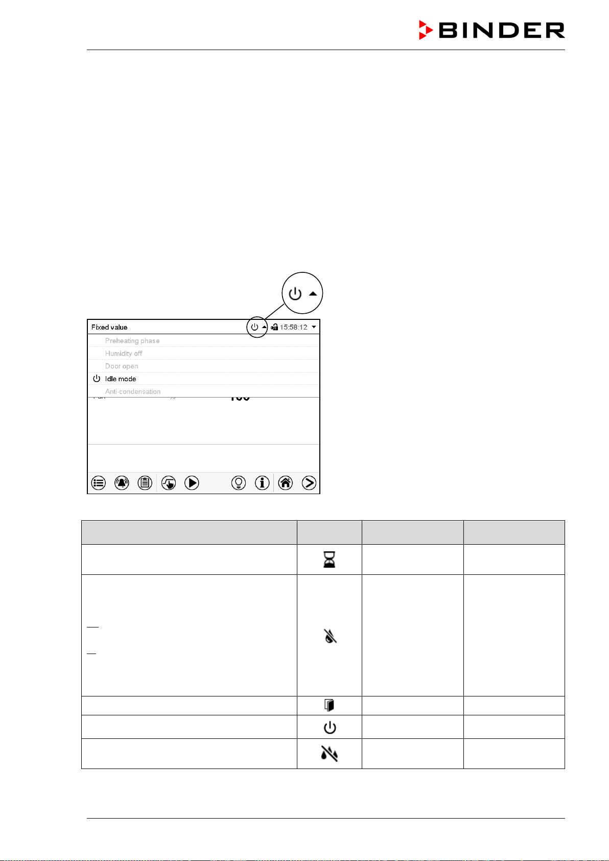
MKF / MKFT (E5) 06/2020 page 79/176
11. Notification and alarm functions
11.1 Notification and alarm messages overview
11.1.1 Notifications
Notifications are indicated by information icons displayed in the screen header in Normal display
An information icon serves as an indication of a certain condition.
If this condition persists, in some cases an alarm will be triggered after a fix or configurable interval. As
long as the condition persists, the information icon therefore continues to be displayed also in state of
alarm. If during alarm the conditions ends, e.g., if during a tolerance range alarm the actual value returns
to within the tolerance range, the information icon disappears, whereas the alarm will continue until man-
ual acknowledgement.
Press the flash icon next to the information icon to access the corresponding text information.
Normal display showing the text information.
The currently valid information texts are high-
lighted in black (example: “Idle mode”)
Condition
Information
icon
Text information
Start after
condition occurred
1-hour preheating phase, no cooling or de-
humidification
“Preheating phase”
immediately
The humidification / dehumidification system
is turned off (via operation line and/or by
setting “Control on/off”)
or Temperature setpoint below 0 °C or above
95 °C
or humidity out of control range.
No active humidification of the inner cham-
ber. Cooling operation may cause further
dehumidification.
“Humidity off” immediately
Open chamber door
“Door open” immediately
The controller is in Idle mode (chap. 5.4).
“Idle mode” immediately
Operation line “Anti-condensation” on. Anti-
condensation protection is activated
“Anti-condensation” immediately
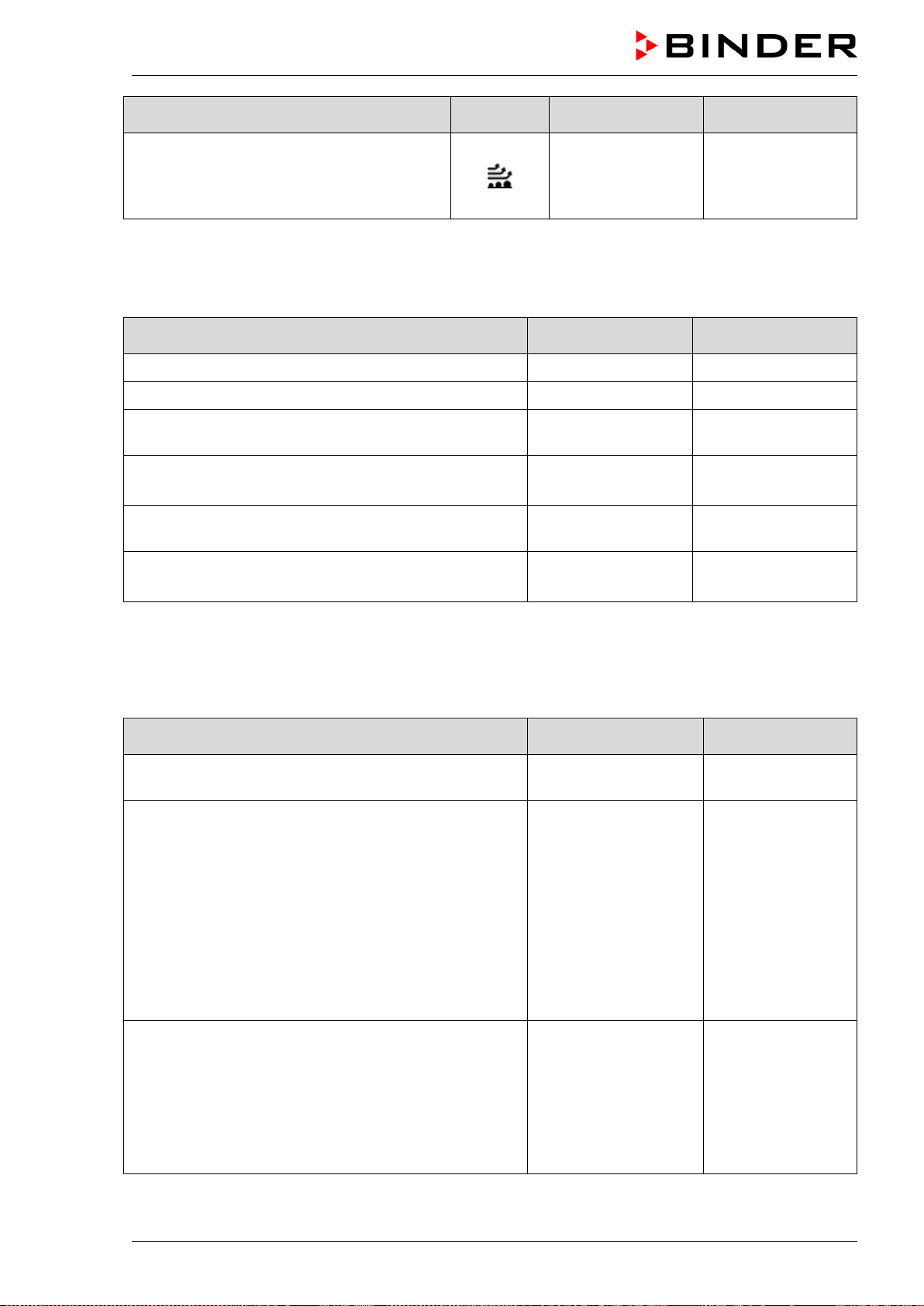
MKF / MKFT (E5) 06/2020 page 80/176
Condition
Information
icon
Text information
Start after
condition occurred
Operation line “Compr. air dryer” on. Option-
al compressed air dryer activated.
Turn operation line off when not using the
compressed air dryer!
“Compressed Air
Dryer”
immediately
Notifications are not shown in the event list.
11.1.2 Alarm messages
Condition Alarm message
Start after
condition occurred
Chamber door open “Door open after 5 minutes
Exceeded setpoint of the safety controller class 2 “Safety controller immediately
Exceeded maximum or minimum temperature (option
temperature safety device class 2)
“Temperature safety
device”
immediately
Temperature sensor defective
e.g. “- - - - ” or
“<-<-<” or “>->->”
immediately
Safety controller temperature sensor defective
“Safety controller
sensor”
immediately
MKF/MKFT 115, 240, 720:
Fault in refrigerating machine. Contact BINDER service.
Compressor
overcurrent
immediately
Alarm messages are displayed in the list of active alarms until acknowledging them. They are also shown
in the event list.
11.1.3 Messages concerning the humidity system
Condition and measures Message
Start after condition
occurred
The humidity module is defective. Contact BINDER
service
“Humidity system” immediately
MKF 56:
The humidity module cannot fill up.
In case of freshwater supply via water pipe:
The water tap is closed, or the chamber is defective
(e.g. inlet valve of humidity module).
In case of freshwater supply via external freshwater can
(option):
Water can is empty. Humidification is turned off. In case
of refrigerating operation, the interior is strongly dehu-
midified. When the water supply is functional again, the
humidity system restarts, or the chamber is defective.
“Freshwater supply” immediately
MKF/MKFT 115, 240, 720:
Freshwater can is too empty to allow normal function, or
the floating switch is defective.
The humidification system turns off.
Fill up the water can or open the water supply.
During the one-hour preheating phase: message without
significance.
“Freshwater can
empty”
after 60 sec.
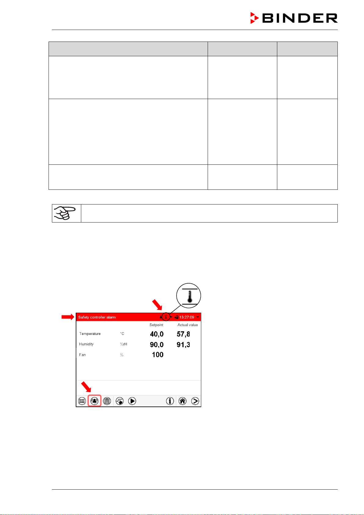
MKF / MKFT (E5) 06/2020 page 81/176
Condition and measures Message
Start after condition
occurred
MKF/MKFT 115, 240, 720:
Freshwater can is too full, or the floating switch is defec-
tive. Suck off the water (chap. 4.2.3). The chamber func-
tions as usual.
If the message persists, contact BINDER service.
“Freshwater can
overflow”
after 60 sec.
The humidity module cannot empty the condensate
tank.
Wastewater tube obstructed. Check the length and loca-
tion of the wastewater tube. If appropriate, contact
BINDER service.
or
Wastewater pump or floating switch of the wastewater
tank defective. Contact BINDER service.
“Wastewater” immediately
Maintenance of the humidity system is required. Contact
BINDER service.
“Humidity module
service”
after predefined
time (approx. 1
year)
Messages concerning the humidity system are shown in the event list.
When operating the chamber without water connection, turn off humidity control in the “set-
points” menu (chap. 6.3) in order to avoid humidity alarms.
11.2 State of alarm
1. Visual indications in Normal display: alarm message, screen header flashing in red color
2. Audible alert, if the buzzer is enabled (chap. 11.4).
Normal display in state of alarm (example).
(a)
Screen header flashing in red color and
showing the alarm message
(b) Alarm
icon on the bottom of the screen:
change to the list of active alarms and
alarm acknowledgement
(c) If applicable, information icon in the screen
header. Indication of a certain condition
(a)
(c)
(b)
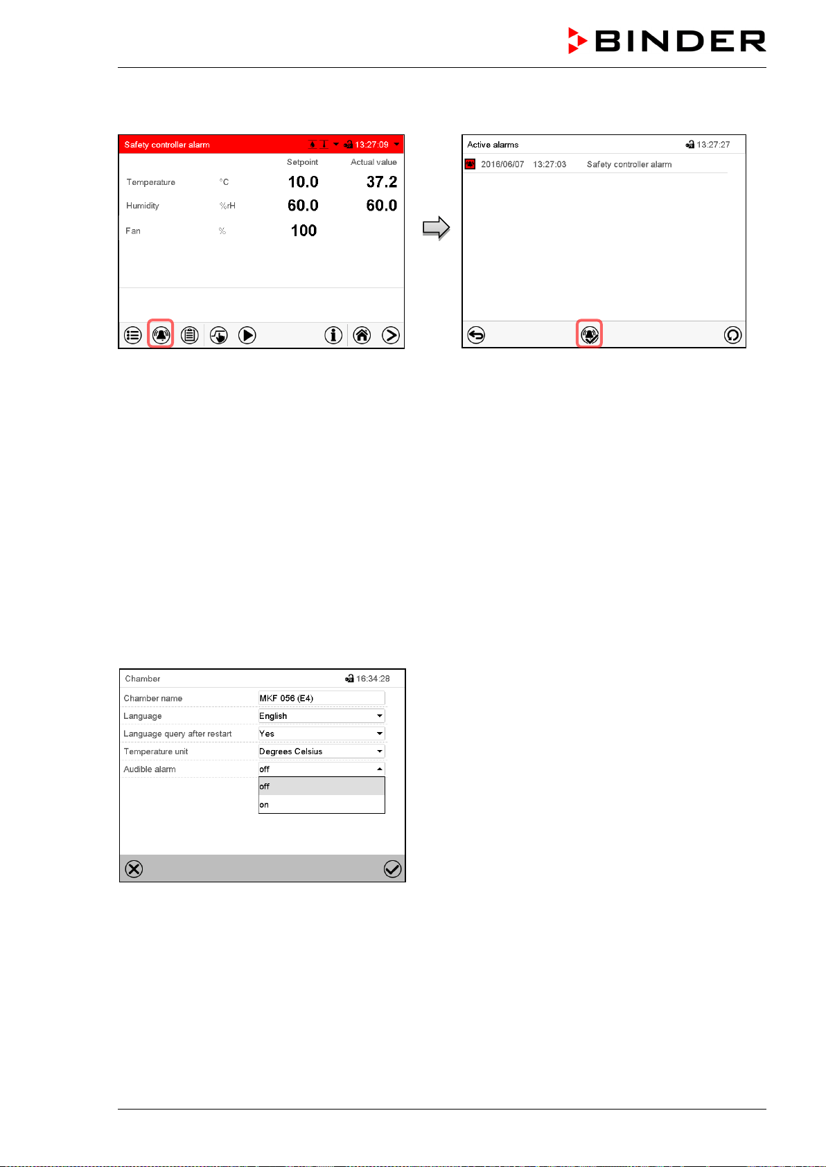
MKF / MKFT (E5) 06/2020 page 82/176
11.3 Resetting an alarm, list of active alarms
Normal display in state of alarm (example).
Press the Alarm icon
List of active alarms.
Press the Reset alarm icon.
Pressing the Reset alarm icon mutes the buzzer for all active alarms. The icon then disappears.
• Acknowledging while the alarm condition persists: Only the buzzer turns off. The visual alarm indica-
tion remains on the controller display. The alarm remains in the list of active alarms.
When the alarm condition has ended, the visual alarm indication is automatically cleared. The alarm is
then no longer in the list of active alarms.
• Acknowledging after the alarm condition has ended: The buzzer and the visual alarm indication are
reset together. The alarm is then no longer in the list of active alarms.
11.4 Activating / deactivating the audible alarm (alarm buzzer)
Path: Main menu > Settings > Chamber
“Chamber” submenu (example).
In the field “Audible alarm” select the desired setting
“off“ or “on” and press the Confirm icon.
MKF / MKFT (E5) 06/2020 page 83/176
12. Temperature safety devices
12.1 Over temperature protective device (class 1)
The chamber is equipped with an internal temperature safety device, class 1 acc. to DIN 12880:2007. It
serves to protect the chamber and prevents dangerous conditions caused by major defects.
If the actual temperature exceeds the nominal temperature by approx. 20 °C, the over temperature pro-
tective device permanently turns off the chamber. The user cannot restart the device again. The protec-
tive cut-off device is located internally. Only a service specialist can replace it. Therefore, please contact
an authorized service provider or BINDER service.
12.2 Safety controller (over temperature safety device class 2)
The chambers are regularly equipped with an electronic overtemperature safety controller (temperature
safety device class 2 according to DIN 12880:2007). The safety controller is functionally and electrically
independent of the temperature control system and serves to protect the chamber, its environment and
the contents from exceeding the maximum permissible temperature.
With the option over-/under temperature safety device class 2 (chap. 12.3), the safety control-
ler is not used. In this case it must be set to the maximum temperature.
Please observe the DGUV guidelines 213-850 on safe working in laboratories (for Germany).
When the entered safety controller set-point is reached, the overtemperature safety controller turns off the
heating, fan, refrigeration system and humidifying system. This condition (state of alarm) is indicated vis-
ually and additionally with an audible alert if the buzzer is enabled (chap. 11.4). The alarm persists until
the chamber cools down below the configured safety controller setpoint and the alarm is reset manually.
Check the setting regularly and adjust it following changes of the set-point or charge.
The safety controller only activates after the set-point has been reached once.
12.2.1 Safety controller modes
You can select between “Limit (absolute)” and “Offset (relative)” safety controller mode
• Limit: Absolute maximum permitted temperature value
This setting offers high safety as a defined temperature limit will not be exceeded. It is important to
adapt the safety controller set-point after each modification of the temperature set-point. Otherwise,
the limit could be too high to ensure efficient protection, or, in the opposite case, it could prevent the
controller from reaching an entered set-point outside the limit range.
• Offset: Maximum overtemperature above any active temperature set point. The maximum tempera-
ture changes internally and automatically with every set-point change.
This setting is recommended for program operation. It is important to check the safety controller set-
point and safety controller mode occasionally, as it does not offer a fix, independent limit temperature
value, which would never be exceeded.
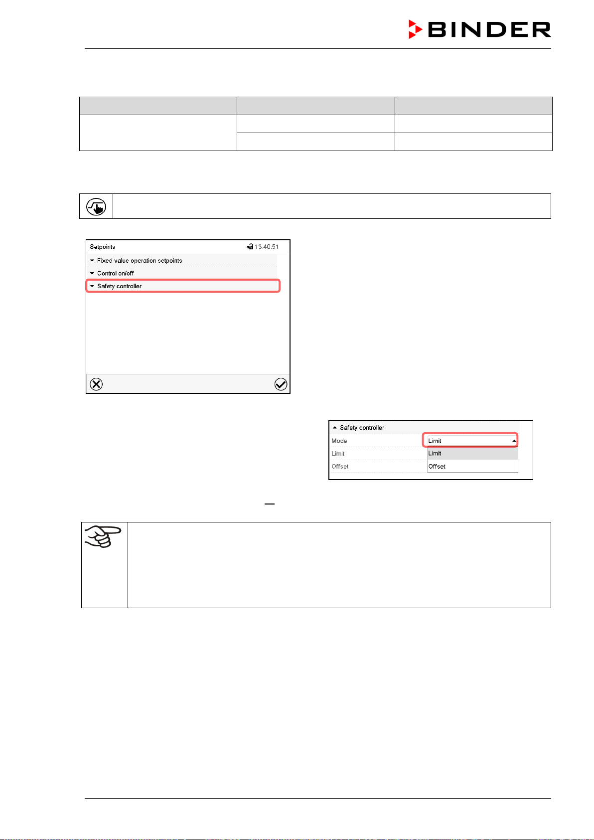
MKF / MKFT (E5) 06/2020 page 84/176
Example: Desired temperature value: 40 °C, desired safety controller value: 45 °C.
Possible settings for this example:
Temperature set point Safety controller mode Safety controller set-point
40 °C
Limit (absolute) 45 °C
Offset (relative) 5 °C
12.2.2 Setting the safety controller
Press the Setpoint setting icon to access the “Setpoint” setting menu from Normal display.
“Setpoints” menu.
Select the field “Safety controller” to access the
settings.
• In the field “Mode”
select the desired setting
“Limit” or “Offset”.
• Select the corresponding field “Limit” or “Offset” according to the selected mode and enter the desired
safety controller setpoint. Confirm entry with Confirm icon.
Regularly check the safety controller setting for set-point type “Limit” or “Offset”
• in Fixed value operating mode according to the entered set-point temperature value
• in program mode according to the highest temperature value of the
selected temperature
program
Set the safety controller set-point by approx. 2 °C to 5 °C above the desired temperature set-
point.
After completing the settings, press the Confirm icon to take over the entries and exit the menu, or press
the Close icon to exit the menu without taking over the entries.
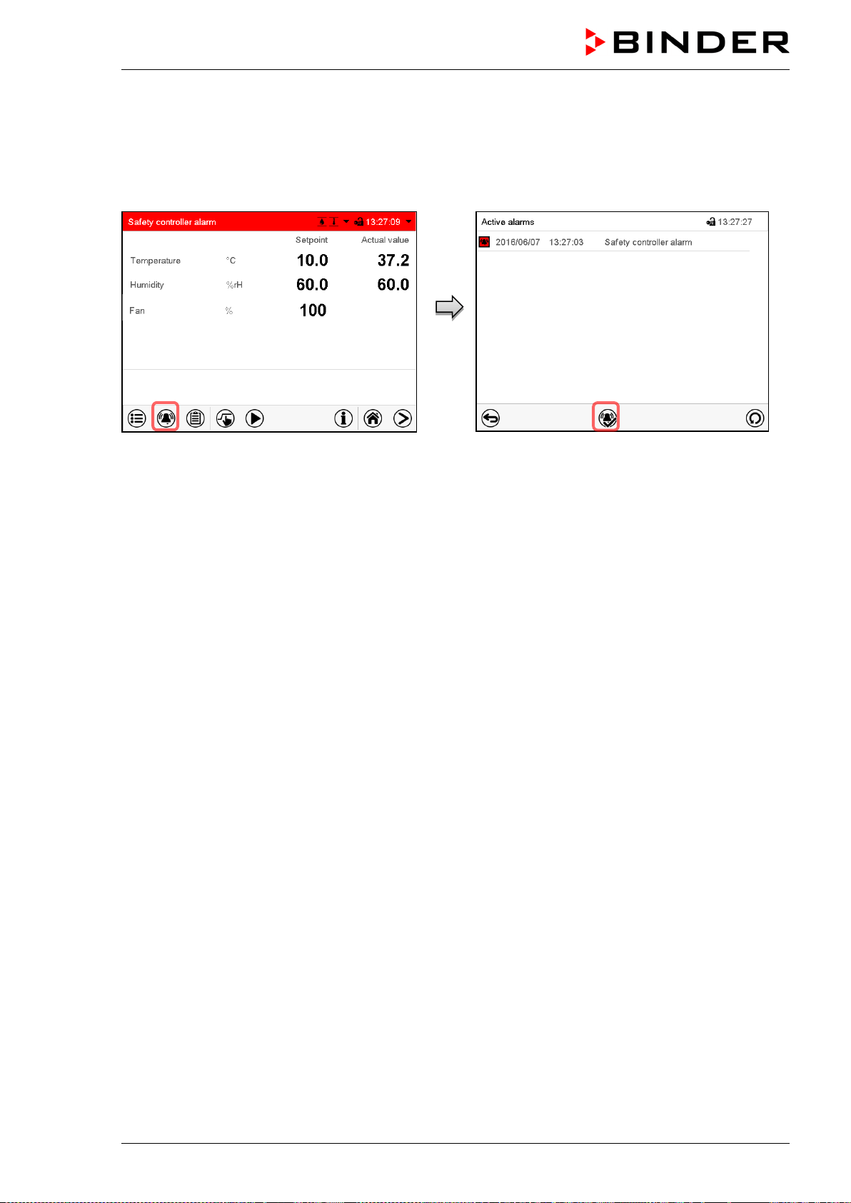
MKF / MKFT (E5) 06/2020 page 85/176
12.2.3 Message and measures in the state of alarm
The state of alarm is indicated visually in Normal display by the alarm message “Safety controller alarm”
and the screen header flashing in red color. If the buzzer is enabled (chap. 11.4) there is an additional
audible alert (chap. 11.2). The alarm remains active until it is acknowledged on the controller and the
inner temperature falls below the set safety controller setpoint. Then the heating is released again.
Normal display with safety controller alarm.
Press the Alarm icon
List of active alarms.
Press the Reset alarm icon.
12.2.4 Function check
Check the safety controller at appropriate intervals for its functionality. It is recommended that the author-
ized operating personnel should perform such a check, e.g., before starting a longer work procedure.
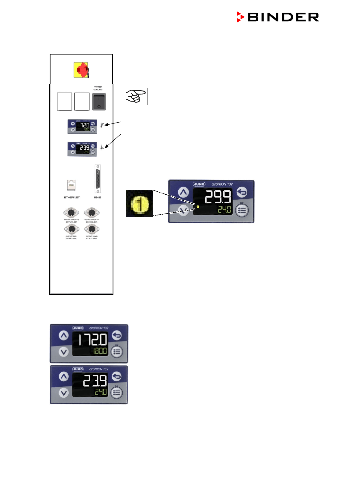
MKF / MKFT (E5) 06/2020 page 86/176
12.3 Over/under temperature safety device class 2 (option)
Example: MKF 56
The over-/under temperature safety device (4) consists of two entry mod-
ules (4a) and (4b) located in the lateral contro
l panel. Both modules can be
set from -50 °C / -58 °F (MKF) / -80 °C / -112 °F (MKFT) up to 200
°C /
392 °F and serve to define the maximum high and low temperature limits.
With this option, the safety controller (chap. 12.2) must be set to
maximum temperature.
(4a) Upper module: Entry of higher limit temperature.
(4b) Lower module: Entry of lower limit temperature.
When the temperature inside the chamber leaves this tolerance band-
width, the temperature control, and herewith the heating and refrigeration,
are turned off permanently.
At the corresponding entry module, the pilot lamp “1” lights up.
The controller displays the alarm message “Temp. safety device”
(chap.
11.1.2
). Additionally there is an audible alert, provided that the buzzer has
not been deactivated (chap. 11.4).
Let the chamber heat up or cool down to the defined safety temperature
range.
Then reset the alarm message on the controller (chap. 11.3). to re-
activate
the chamber. The pilot lamp “1” goes off
as soon as the temperature will
again be below / above the threshold.
Setting limit temperatures at modules (4a) and (4b):
The upper line shows the actual temperature. The bottom line shows
the set-point of the limit temperature.
• Press the arrow-up or arrow-down key
The display changes to entry mode: The set-
point in the bottom
line flashes
• Enter the desired limit temperature via the arrow keys and con-
firm with the “OK” button.
• Press the Back button.
The set-point in the bottom line stops flashing.
Function check:
Check the over/under temperature safety device class 2 at appropriate intervals for its functionality. It is
recommended that the authorized operating personnel should perform such a check, e.g., before starting
a longer work procedure.

MKF / MKFT (E5) 06/2020 page 87/176
13. User management
13.1 Authorization levels and password protection
The available functions depend on the current authorization level “Master”, “Service”, “Admin” or “User”.
The authorization levels are hierarchical: Every authorization includes all functions of the next lower level.
“Master” authorization level
• Highest authorization level, only for developers
• Extensive authorization for controller operation and configuration, outputs/inputs, alarm settings, pa-
rameter sets and operating ring display
• All passwords can be changed in the “log out” submenu (chap. 13.3).
“Service” authorization level
• Authorization level only for BINDER service
• Extensive authorization for controller operation and configuration, access to service data
• The passwords for “Service”, “Admin” and “User” authorization levels can be changed in the “log out”
submenu (chap. 13.3).
“Admin” authorization level
• Expert authorization level, for the administrator
• Authorization for controller configuration and network settings and for operating those controller func-
tions required for operating the chamber. Restricted access to service data.
• Password (factory setting): “2”.
• The passwords for “Admin” and “User” authorization levels can be changed in the “log out” submenu
(chap. 13.3).
“User” authorization level
• Standard authorization level for the chamber operator
• Authorization for operating the controller functions required for operating the chamber.
• No authorization for controller configuration and network settings. The “Settings” and “Service” sub-
menus of the main menu are not available.
• Password (factory setting): “1”
• The password for the “User” authorization level can be changed in the “log out” submenu (chap. 13.3).
As soon as a password has been assigned for an authorization level, the access to this level and the
related controller functions are only available after log-in with the appropriate password.
If for an authorization level no password is assigned, the related controller functions of this level are
available for every user without login.
If passwords have been assigned for all authorization levels, access to the controller functions is locked
without login.
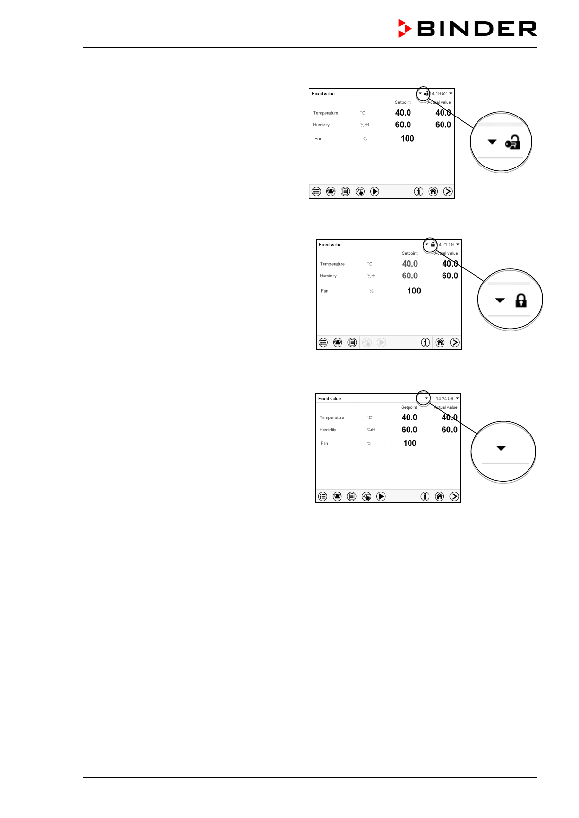
MKF / MKFT (E5) 06/2020 page 88/176
Operation after user login
At user login, the authorization level is selected
and confirmed by entering the respective pass-
word.
Following user login, controller operation is avail-
able, recognizable by the open-lock icon in the
header. The available controller functions corre-
spond to the user’s authorization level.
Password protection activated for all levels: operation without user login is locked
If passwords have been assigned for all authoriza-
tion levels, the controller is locked without registra-
tion of a user.
As long as no user is registered, controller opera-
tion is locked, recognizable at the closed-lock icon
in the header. This requires that the user manage-
ment has been activated by the assignment of
passwords for the individual authorization levels.
Password protection for at least one level deactivated: operation without user login is possible
If passwords have not been assigned for all author-
ization levels, after turning on the chamber there
are those controller functions available, which cor-
respond to the highest authorization level without
password protection.
No lock icon is shown in the display header.
User login is neither required nor possible.
To activate the password protection and user login,
perform new password assignment (chap. 13.5.3).
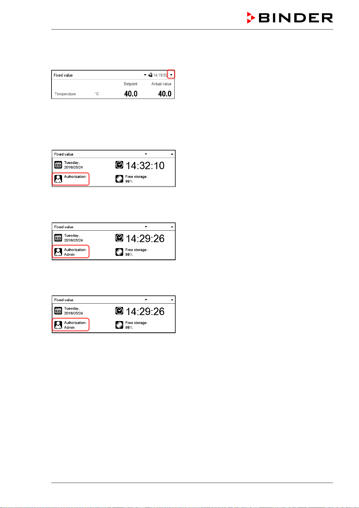
MKF / MKFT (E5) 06/2020 page 89/176
Information window
To check the authorization level of the user currently logged-in, select in Normal display the arrow far
right in the display header.
The information window shows date and time, the controller’s free memory space and under “Authoriza-
tion” the authorization level of the current user.
If passwords have been assigned for all authorization levels, a user without login (password entry) has no
authorization. There are only viewing functions available.
Display when all authorization levels are password pro-
tected and no user has logged in:
No authorization level is displayed.
If passwords have been assigned only for some of the authorization levels, a user without login (pass-
word entry) has access to the functions of the highest authorization level without password protection.
Display when only some of the authorization levels are
password protected (example: no protection for the
“User” and “Admin” levels) and no user has logged in:
The user’s effective authorization (due to lack of pass-
word protection) is shown.
Example: user with “Admin” authorization.
If passwords have been assigned for some or all of the authorization levels, user login (password entry)
provides the authorization for the corresponding password-protected level.
Display when at least some of the authorization levels
are password protected and a user has logged in.
The user’s authorization (by password entry) is shown.
Example: user with “Admin” authorization.
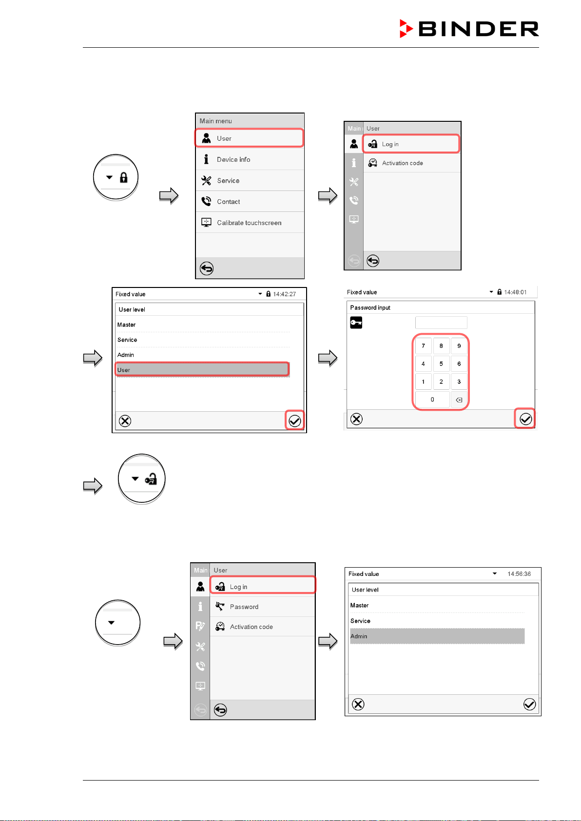
MKF / MKFT (E5) 06/2020 page 90/176
13.2 Log in
Path: Main menu > User > Log in
Controller
without a user
logged-in
Selection of user type (example) All selection possibilities are password protected
Controller with logged-in user
After completing the settings, press the Confirm icon to take over the entries and exit the menu, or press
the Close icon to exit the menu without taking over the entries.
Controller with
deactivated
password
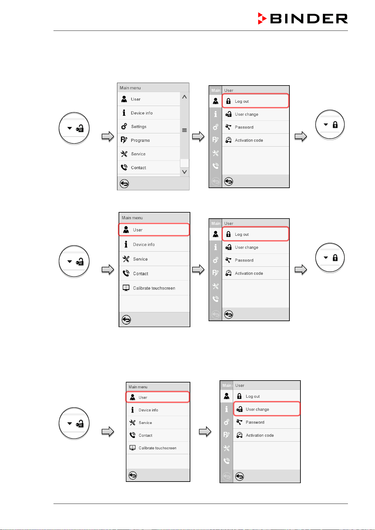
MKF / MKFT (E5) 06/2020 page 91/176
13.3 Log out
Path: Main menu > User > Log out
User logoff with “Admin” authorization
Controller with
logged-in user
Controller
without a user
logged-in
User logoff with “User” authorization
Controller with
logged-in user
Controller
without a user
logged-in
13.4 User change
If the password function has been deactivated (chap.13.5.2) this function is not available.
Path: Main menu > User > User change
Contr
oller with
logged-in user
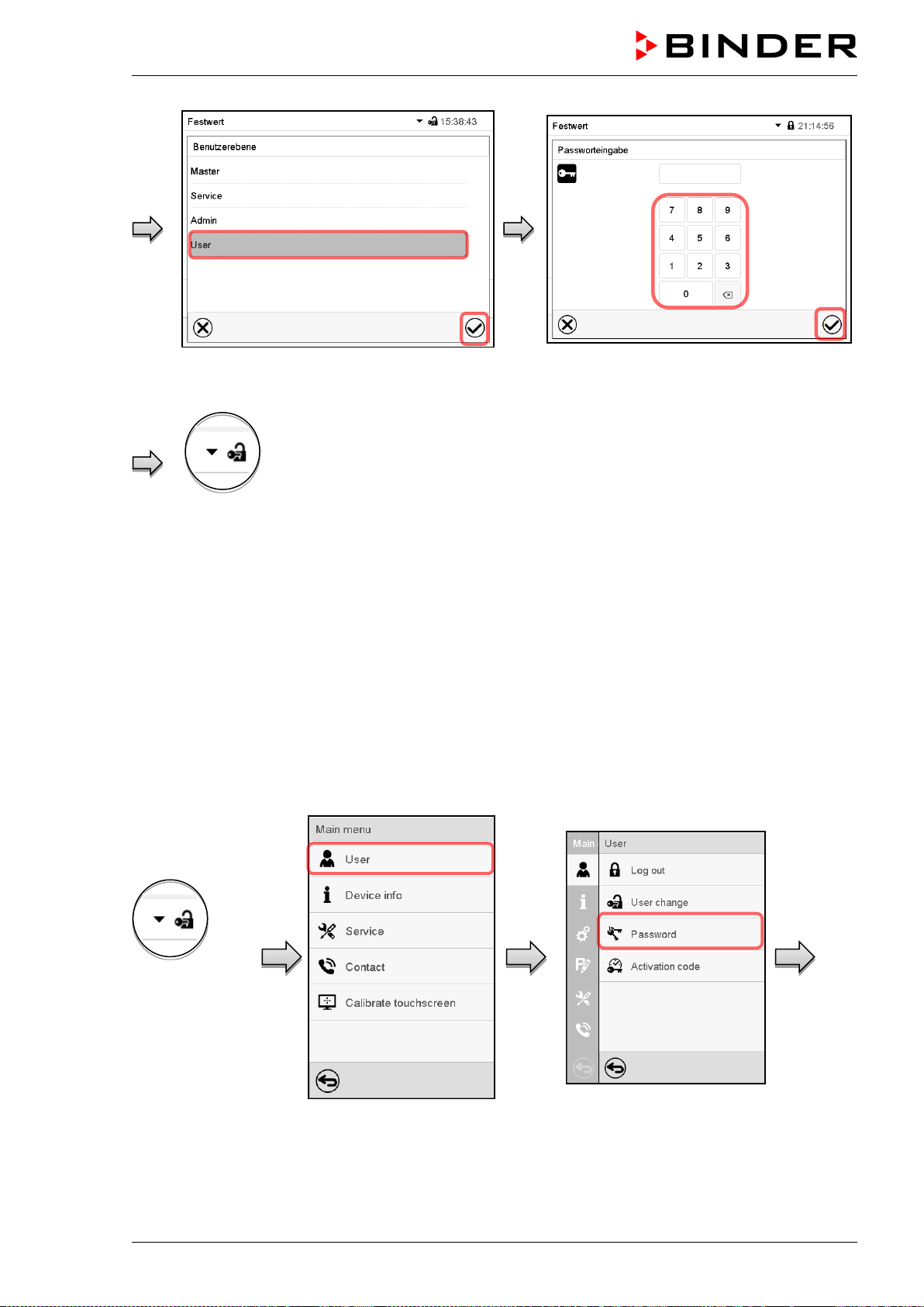
MKF / MKFT (E5) 06/2020 page 92/176
User selection (example) All selection possibilities are password protected
Controller with logged-
in user
13.5 Password assignment and password change
This function is not available for a user logged-in with “User” authorization.
13.5.1 Password change
A logged-in user can change the passwords of his current level and of the next lower level(s).
Example: A user with “Admin” authorization can change the passwords for the “Admin” and “User” au-
thorization levels.
Path: Main menu > User > Password
User logged-in
with “Service” or
“Admin”
authorization
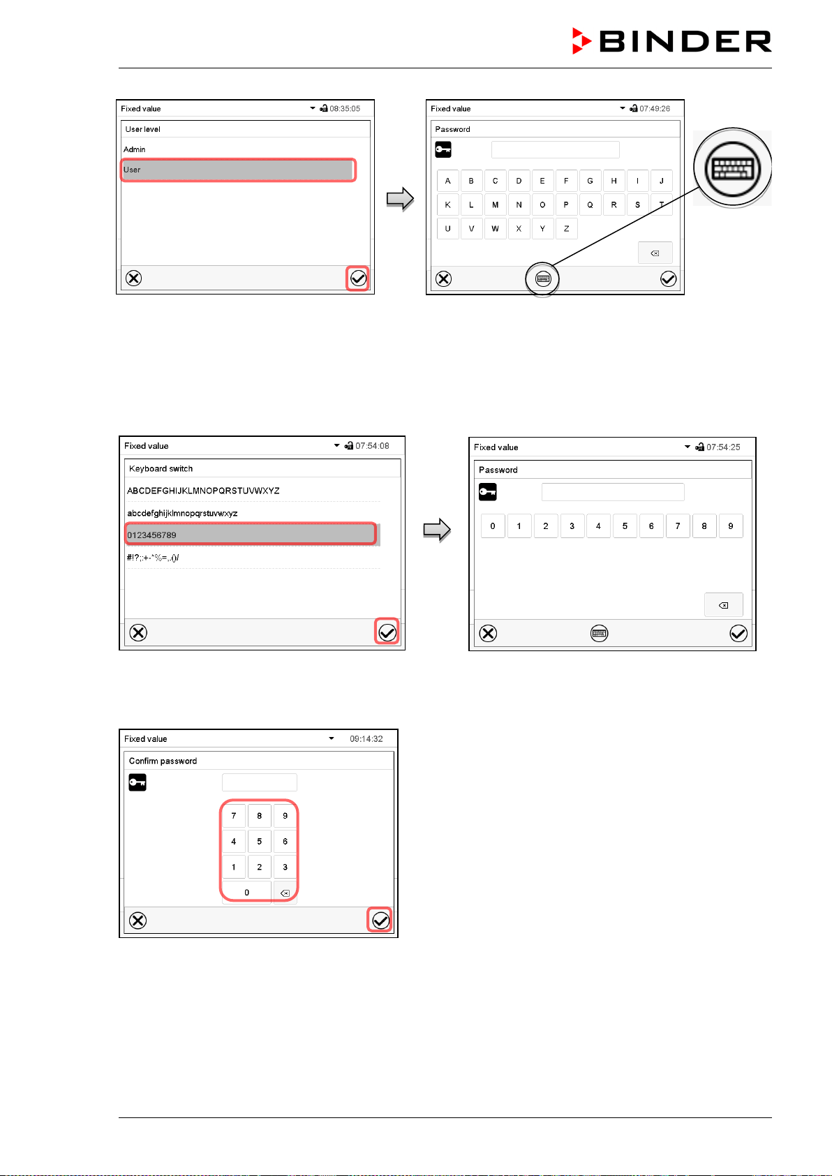
MKF / MKFT (E5) 06/2020 page 93/176
Selection of the authorization level
(example: view with “Admin” authorization)
Enter desired password. If desired, press the
Change keyboard icon to access other entry win-
dows.
In the “Keyboard switch” window you can select different keyboards to enter uppercase and lowercase
letters, digits, and special characters. All types of characters can be combined within one single pass-
word.
Example: access the digit entry window
Entry of digits
To confirm the entry, press the Confirm icon.
Repeat the password entry for confirmation (sample
picture). For each character of the password, the re-
quired keyboard appears automatically.
Then press the Confirm icon.
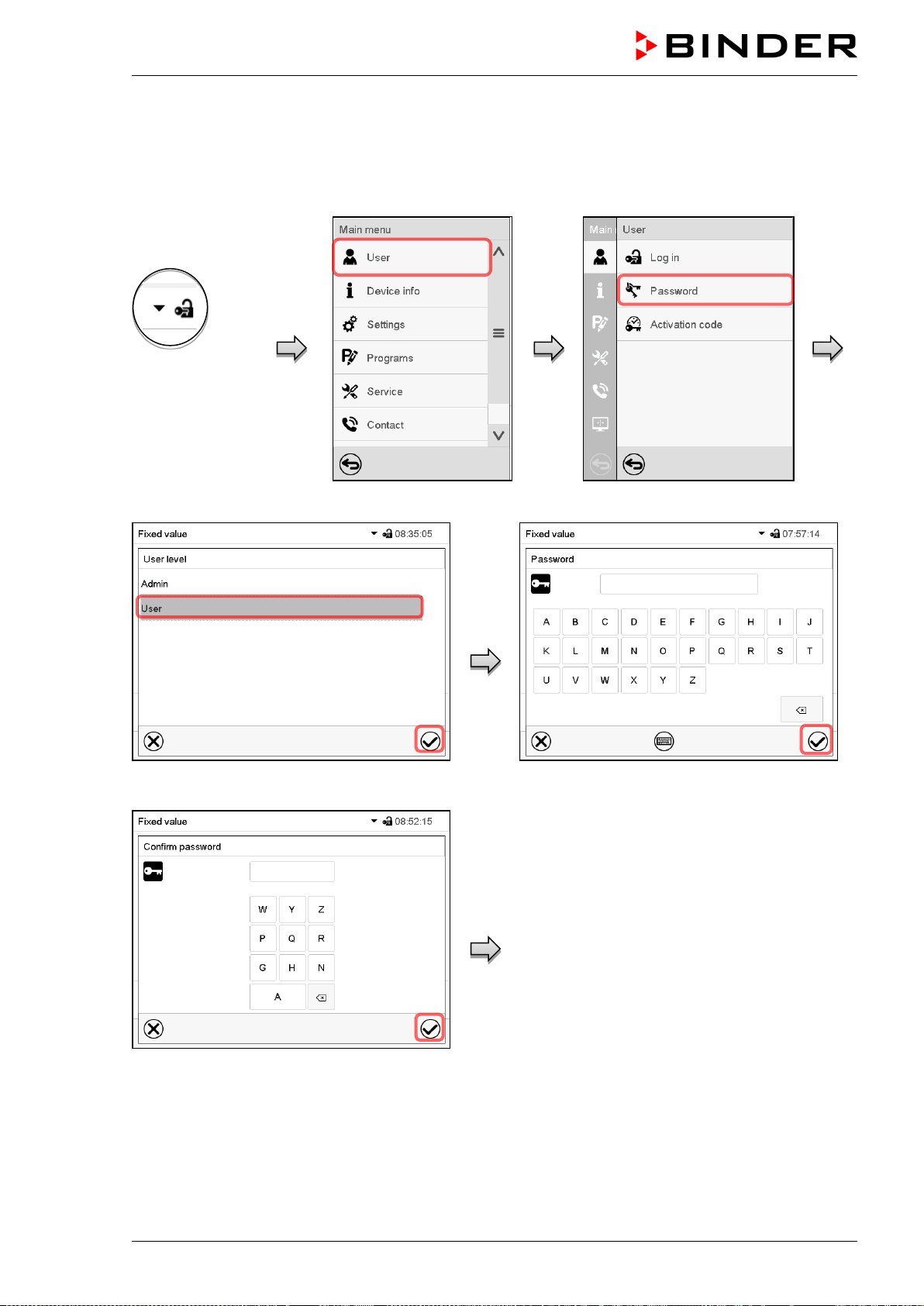
MKF / MKFT (E5) 06/2020 page 94/176
13.5.2 Deleting the password for an individual authorization level
A user logged-in with “Service” or “Admin” authorization can delete the passwords of his current level and
of the next lower level(s). To do this no password is entered during a password change.
Path: Main menu > User > Password
Controller with
logged-in user
(e.g. with “Admin”
authorization)
Select the authorization level for which the
password shall be deleted.
Do NOT enter anything in the “Password”
screen. Press the Confirm icon.
Do NOT enter anything in the “Confirm
password” screen. Press the Confirm icon.
The password is deleted.
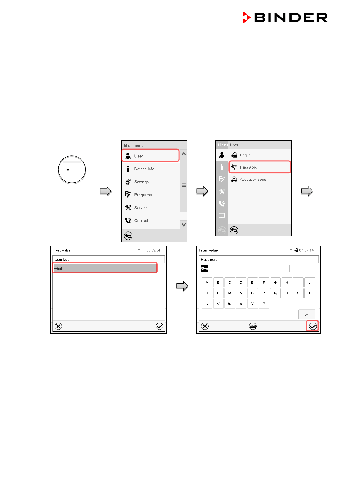
MKF / MKFT (E5) 06/2020 page 95/176
13.5.3 New password assignment for “service” or “admin” authorization level when the
password function was deactivated
If the password protection for an authorization level has been deactivated, i.e., no password is assigned,
no login for this level is possible. Therefore access to this authorization level is available without login.
If the password for the “Service” or “Admin” authorization has been deleted (chap. 13.5.2), a new pass-
word can be assigned for the current level and the next lower level(s) without user login.
Example: The password for the “Admin” authorization level was deleted, therefore every user without
login has full access to the functions of the “Admin” authorization level. If access to this level shall be-
come password protected again, the user can assign a new password for the “Admin” authorization level
with the “Password” function.
Path: Main menu > User > Password
Controller with
deactivated
password for
“Service” or
“Admin” author-
ization
Select the authorization level, for which you
want to assign a password.
(Example: “Admin” authorization)
Enter the desired password. If desired, press the
Change keyboard icon to access other entry
windows.
To confirm the entry, press the Confirm icon.
Repeat the password entry for confirmation. For each character of the password, the required keyboard
appears automatically. Then press the Confirm icon.
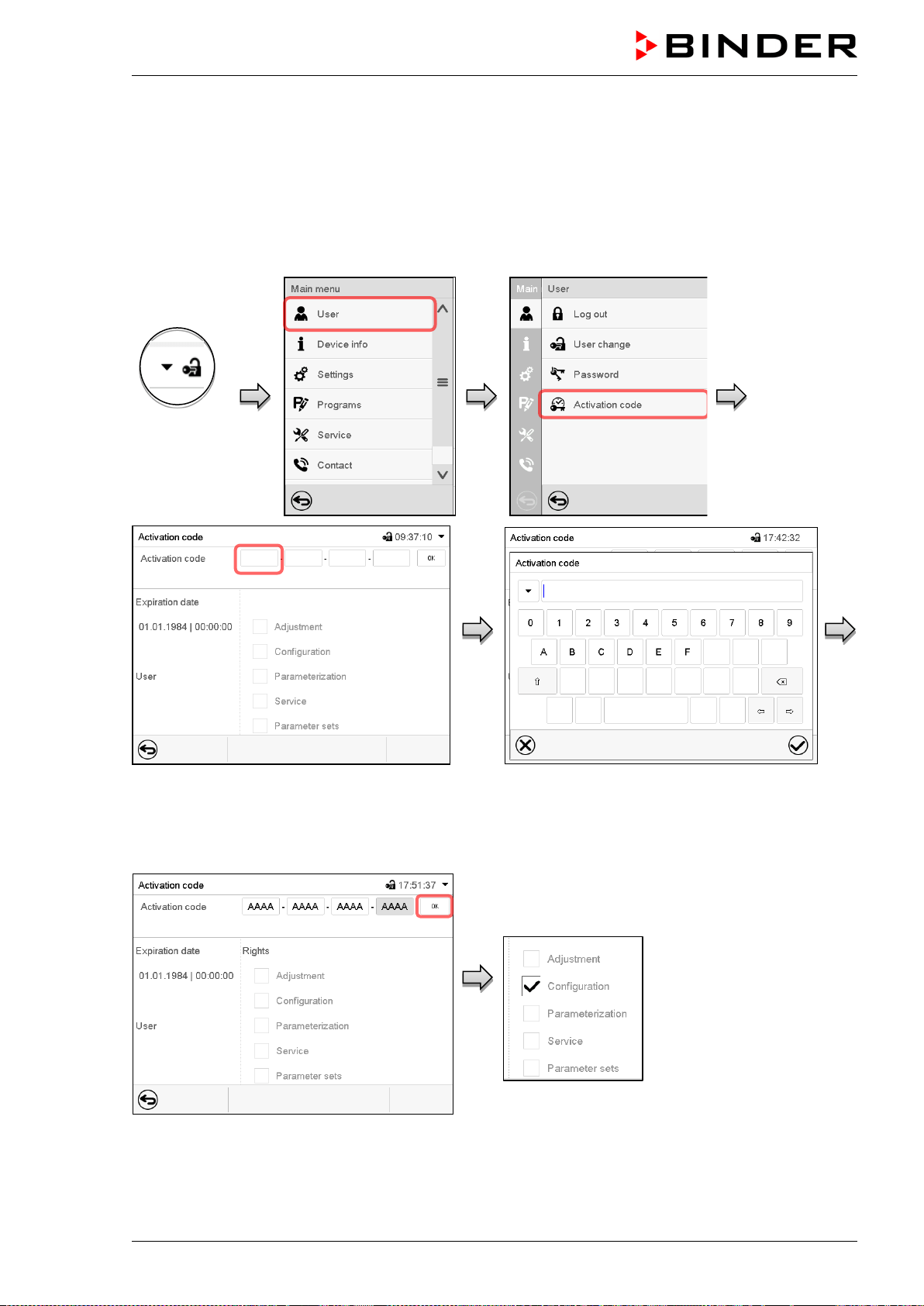
MKF / MKFT (E5) 06/2020 page 96/176
13.6 Activation code
Certain functions of the controller can be unlocked with a previously generated activation code.
The activation code enables access to functions available only in the “Service” authorization level by us-
ers without a “Service” authorization. Such functions include e.g., adjustment or extended configurations.
The activation code is available in authorization levels.
Path: Main menu > User> Activation code
Controller
with logged-
in user
Activation code menu.
Select the first of the four entry fields.
Activation code entry window.
Enter the first four characters of the activation
code and press the Confirm icon.
Select the next of the four entry fields and proceed accordingly until the entire code has been entered.
“Activation code” menu with entered code
(sample view).
Press OK to take over the entry
The available functions are indicated by marked
checkboxes.
Example: Extended configurations available.
Under “Expiration date” the date of expiry of the
code is displayed.
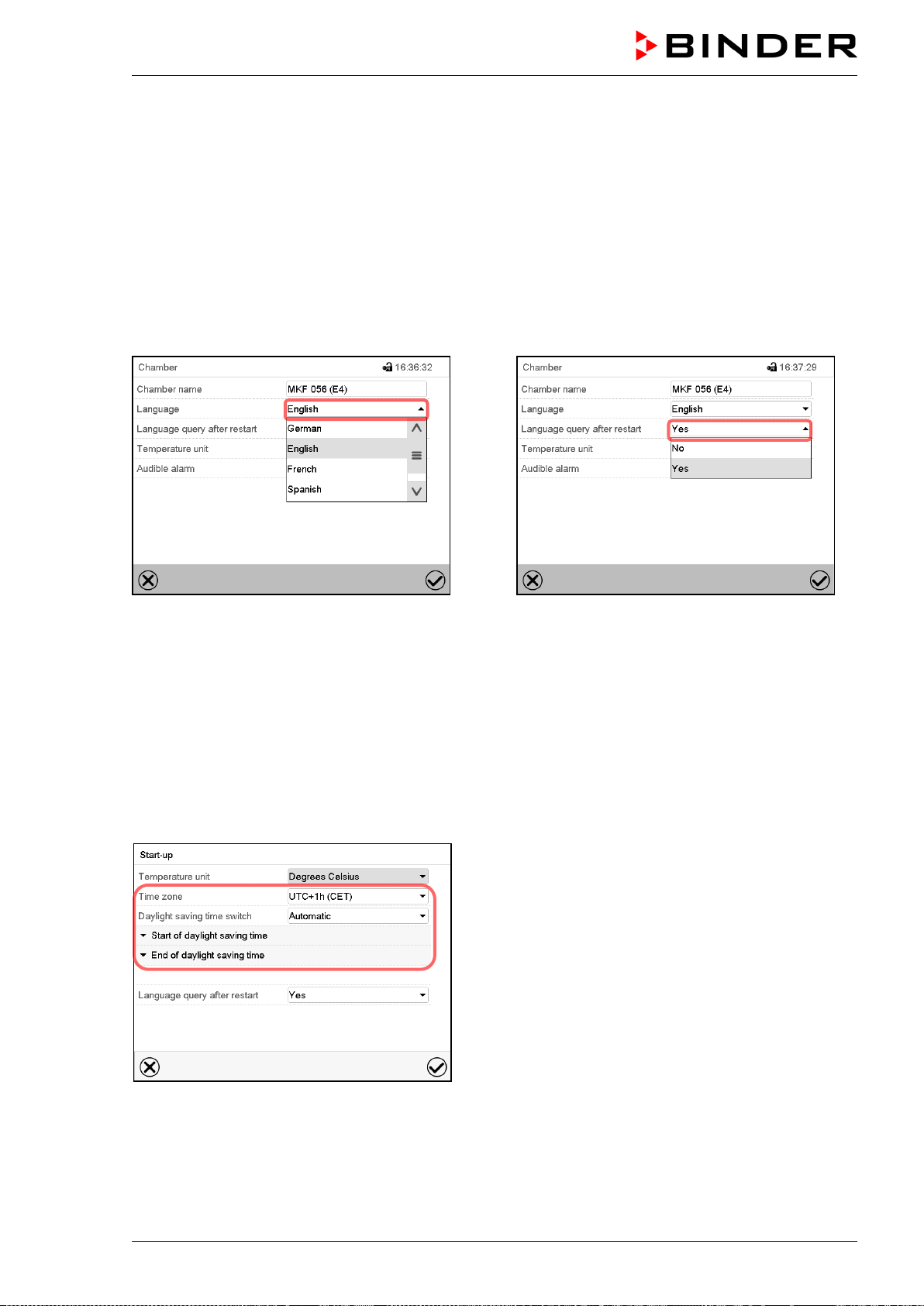
MKF / MKFT (E5) 06/2020 page 97/176
14. General controller settings
Most of the general settings can be accessed in the “Settings” submenu, which is available for users with
“Service” or “Admin” authorization level. It serves to enter date and time, select the language for the con-
troller menus and the desired temperature unit and to configure the controller’s communication functions.
14.1 Selecting the controller’s menu language
The MB2 program controller communicates by a menu guide using real words in German, English,
French, Spanish, and Italian.
Path: Main menu > Settings > Chamber
“Chamber” submenu.
Select the desired language.
“Chamber” submenu.
Select if there shall be a language query after
restarting the chamber and press the Confirm
icon.
Return to Normal display with the Back icon to take over the entries.
14.2 Setting date and time
Following start-up of the chamber after language selection:
Select the time zone and configure the daylight
saving time switch.
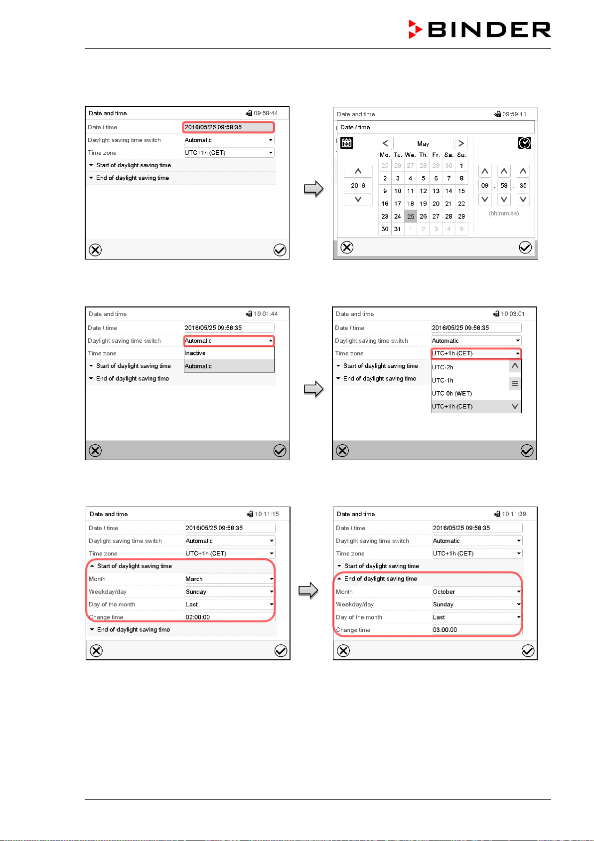
MKF / MKFT (E5) 06/2020 page 98/176
Or later:
Path: Main menu > Settings > Date and time
“Date and time” submenu.
Select the field “Date / time”.
“Date / time” entry menu.
Enter date and time and press the Confirm
icon.
“Date and time” submenu.
In the field “Daylight saving time switch” select
the desired setting “Automatic” or “Inactive”.
“Date and time” submenu.
Select the desired time zone and press the
Confirm icon.
“Date and time” submenu.
Select the desired start of the daylight saving
time.
“Date and time” submenu.
Select the desired end of the daylight saving
time and press the Confirm icon.
After completing the settings, press the Confirm icon to take over the entries and exit the menu, or press
the Close icon to exit the menu without taking over the entries.
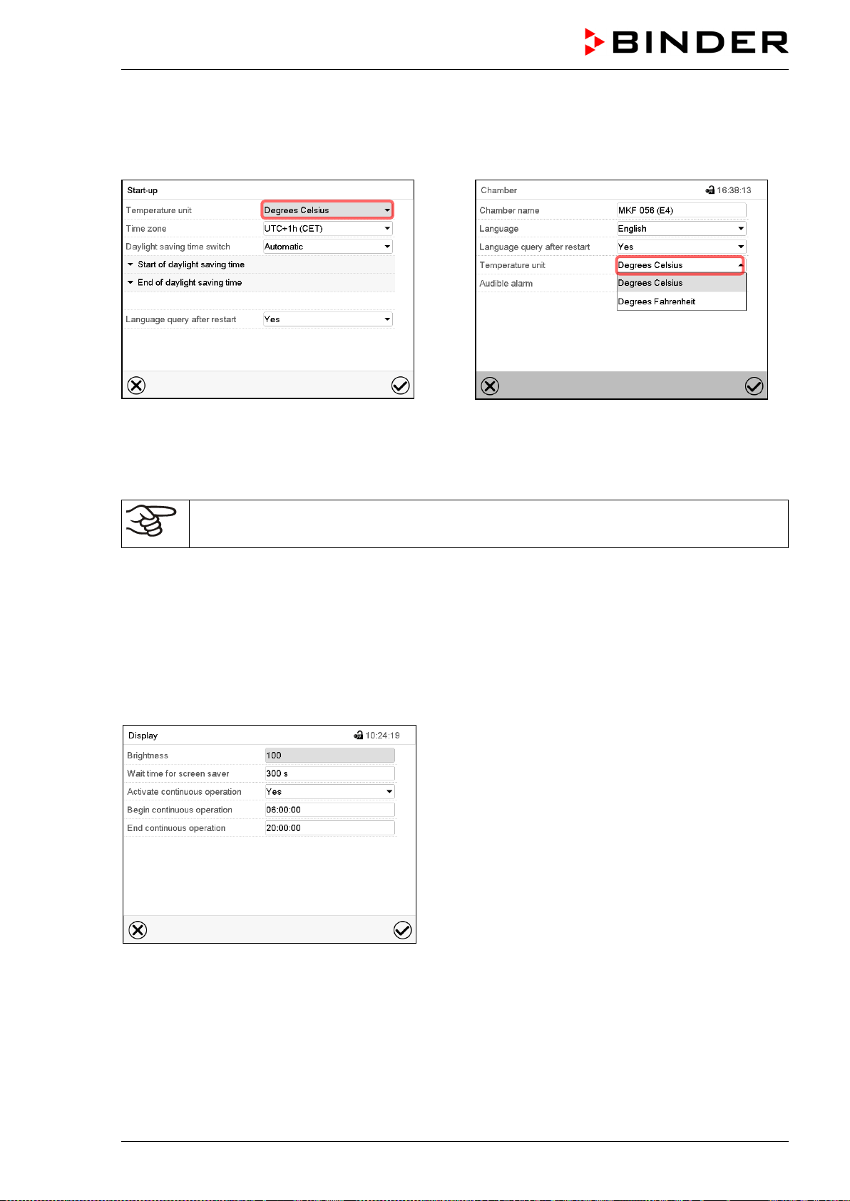
MKF / MKFT (E5) 06/2020 page 99/176
14.3 Selecting the temperature unit
Following start-up of the chamber:
Or later:
Path: Main menu > Settings > Chamber
Select the desired temperature unit and press
the Confirm icon.
Change of the temperature unit between °C and °F.
If the unit is changed, all values are converted accordingly
C = degree Celsius
F= degree Fahrenheit
0 °C = 31°F
100 °C = 212°F
Conversion:
[value in °F] = [value in °C] ∗ 1,8 + 32
14.4 Display configuration
14.4.1 Adapting the display parameters
This function serves to configure parameters like display brightness and operating times.
Path: Main menu > Settings > Display > Display
“Display” submenu.
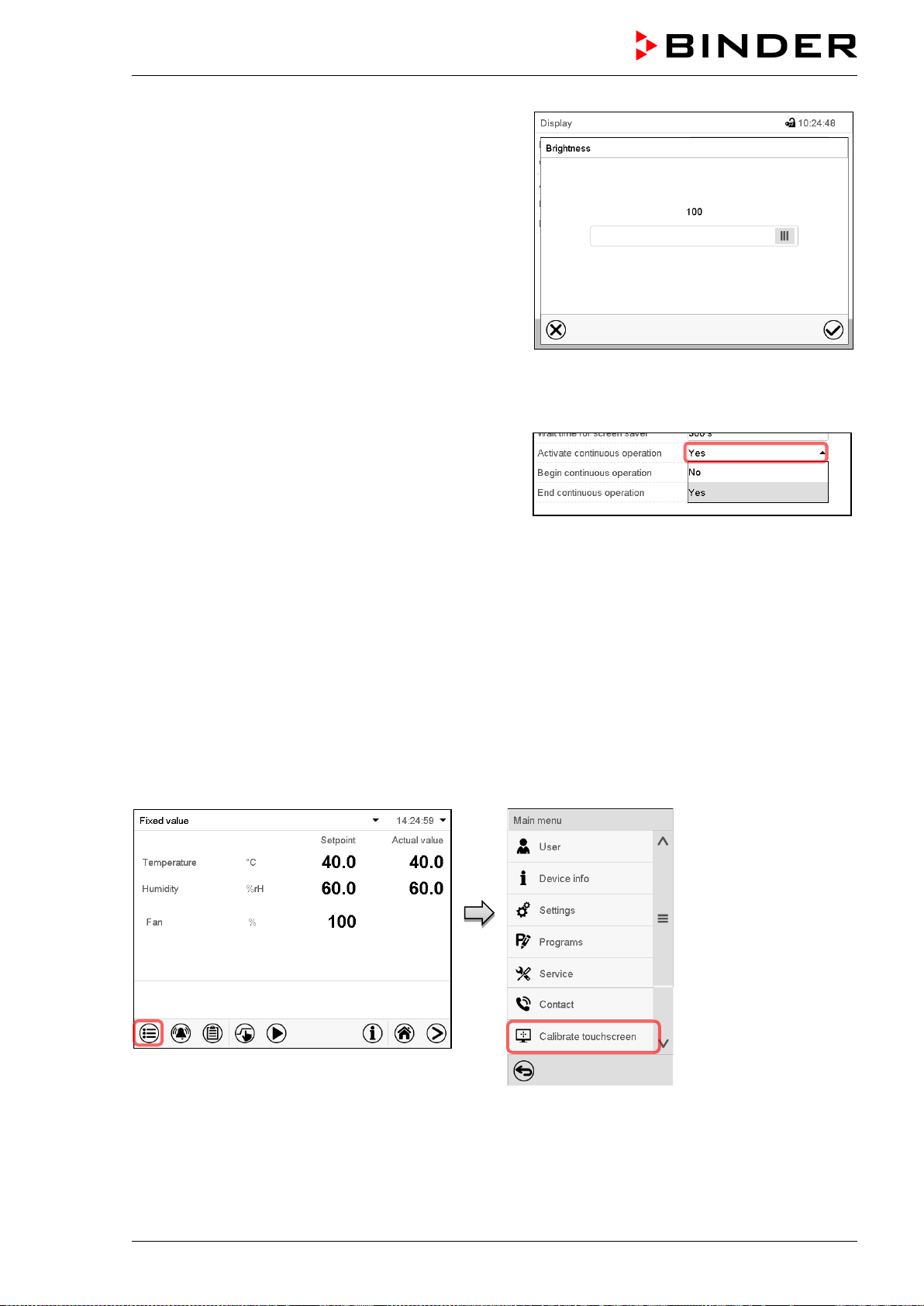
MKF / MKFT (E5) 06/2020 page 100/176
• Select the field “Brightness”.
Move the grey slide to the left or right to define the
brightness of the display
• left = darker (minimum value: 0)
• right = brighter (maximum value: 100)
Press the Confirm icon.
• Select the field “Wait time for screen saver” and enter the desired waiting time for the screen saver in
seconds. Setting range: 10 sec up to 32767 sec. During the waiting time the display is off. Confirm
entry with Confirm icon.
• In the field “Activate continuous operation” select the
desired setting “Yes” or “No”.
• Select the field “Begin continuous operation” (possible only if continuous operation is activated) and
enter the time with the arrow keys. Confirm entry with Confirm icon.
• Select the field “End continuous operation. (only possible if continuous operation is activated) and
enter the time with the arrow keys. Confirm entry with Confirm icon.
After completing the settings, press the Confirm icon to take over the entries and exit the menu, or press
the Close icon to exit the menu without taking over the entries.
14.4.2 Touchscreen calibration
Path: Main menu > Calibrate touchscreen
Normal display.
Select “Calibrate touchscreen” and follow the instructions on the display.
You need to touch all four corners of the touchscreen to calibrate it. Appropriate boxes appear succes-
sively in each corner.
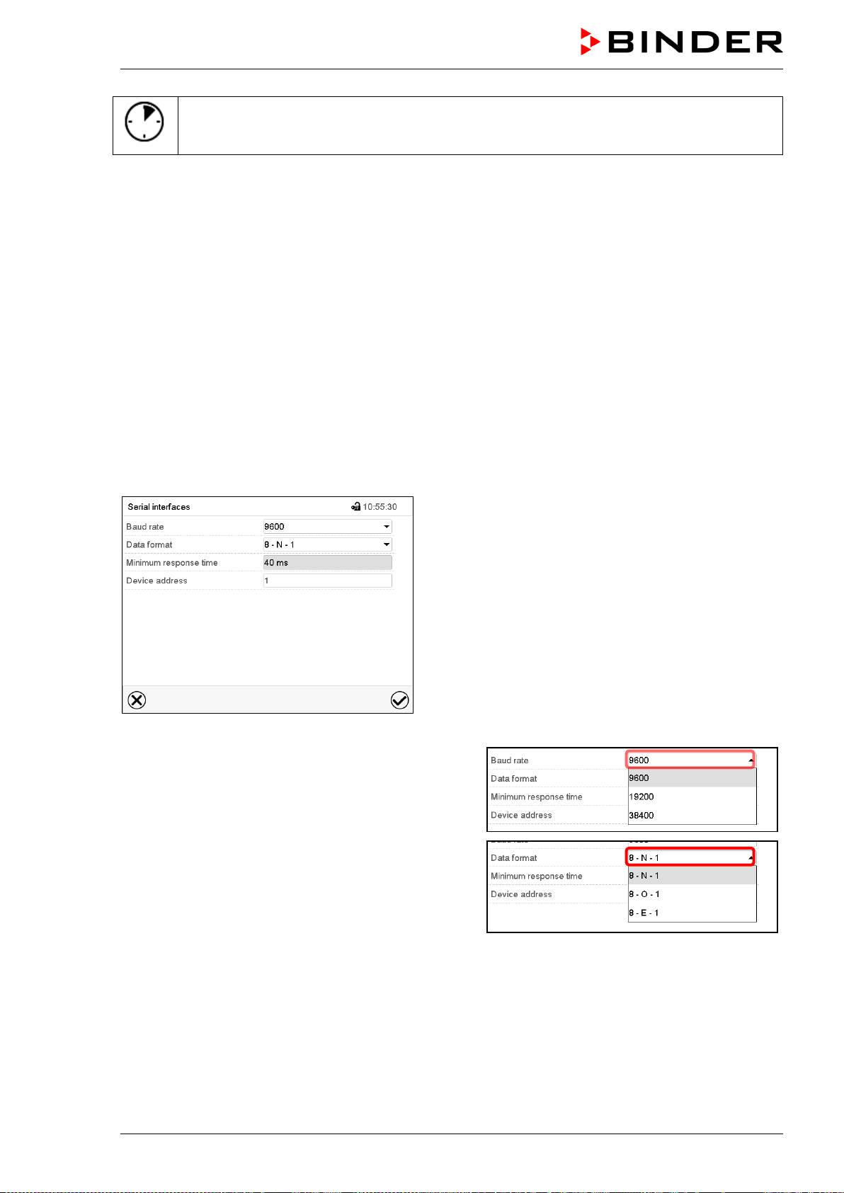
MKF / MKFT (E5) 06/2020 page 101/176
The waiting icon shows how much time there is left to touch the currently activated box. If the
box is not touched withing this period, calibration is aborted and the display changes to
Normal display.
After completing the calibration, i.e., touching all four boxes, the display changes to Normal display.
14.5 Network and communication
For these settings at least the “Admin” authorization level is required.
14.5.1 Serial interfaces
The chamber is optionally equipped with a serial RS485 interface.
This menu allows to configure the communication parameters of the RS485 interface.
The device address is required to recognize chambers with this interface type in a network, e.g. when
connecting it to the optional APT-COM™ 4 Multi Management Software (chap. 21.1). In this case do not
change the other parameters.
Path: Main menu > Settings > Serial interfaces
“Serial interfaces” submenu.
• Select the desired setting in the field “Baud rate”.
• Select the desired setting in the field “Data format”.
• Select the field “Minimum response time” and enter the desired minimum response time. Confirm entry
with Confirm icon.
• Select the field “Device address” and enter the device adress. Factory setting is “1”. Confirm entry with
Confirm icon.
After completing the settings, press the Confirm icon to take over the entries and exit the menu, or press
the Close icon to exit the menu without taking over the entries.
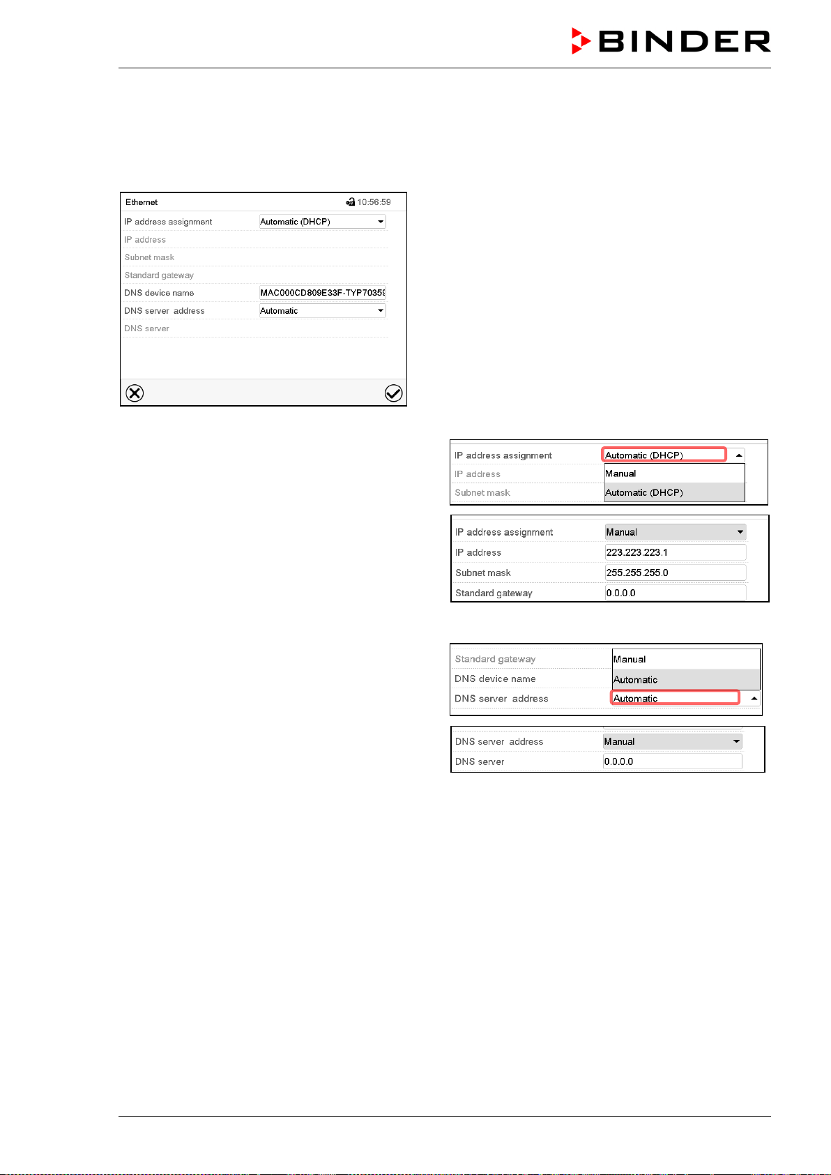
MKF / MKFT (E5) 06/2020 page 102/176
14.5.2 Ethernet
14.5.2.1 Configuration
Path: Main menu > Settings > Ethernet
“Ethernet” submenu.
• In the field “IP address assignment” select the
desired setting “Automatic (DHCP)“ or “Manual“.
With selection “Manual” you can enter the IP-
address, the subnet mask and the standard
gateway manually.
• Select “DNS device name” and enter the DNS device name. Confirm entry with Confirm icon.
• In the field “DNS server address” select the de-
sired setting “Automatic” or “Manual”.
With selection „Manual“ you can enter the DNS
server address manually.
After completing the settings, press the Confirm icon to take over the entries and exit the menu, or press
the Close icon to exit the menu without taking over the entries.
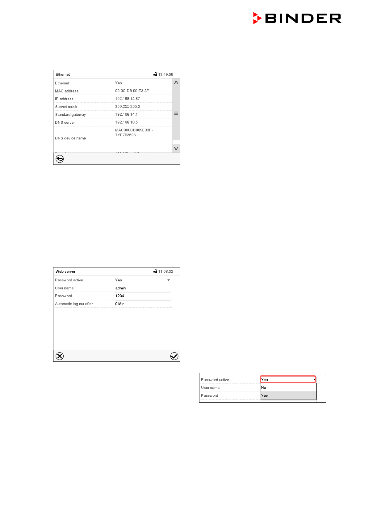
MKF / MKFT (E5) 06/2020 page 103/176
14.5.2.2 Display of MAC address
Path: Main menu > Device info > Ethernet
“Ethernet” submenu (example).
14.5.3 Web server
This controller menu serves to configure the web server. Then you can enter the chamber’s IP-address in
the Internet. The IP address is available via Chamber information > Ethernet. The BINDER web server
opens. Enter the user name and password which have been assigned for the web server in the controller
menu. This enables online access to the controller display, to see e.g., the event list or error messages.
In this view no settings can be changed.
Path: Main menu > Settings > Web server
“Webserver” submenu.
• In the field “Password active” select the desired
setting “Yes” or “No”.
• Select the field “User name” and enter the desired user name. Confirm entry with Confirm icon.
• Select the field “Password” and enter the desired password. Confirm entry with the Confirm icon.
• Select the field “Automatic log out after” and enter the time in minutes after which the webserver shall
log out automatically. Setting range: 0 min to 65535 min. Confirm entry with Confirm icon.
After completing the settings, press the Confirm icon to take over the entries and exit the menu, or press
the Close icon to exit the menu without taking over the entries.
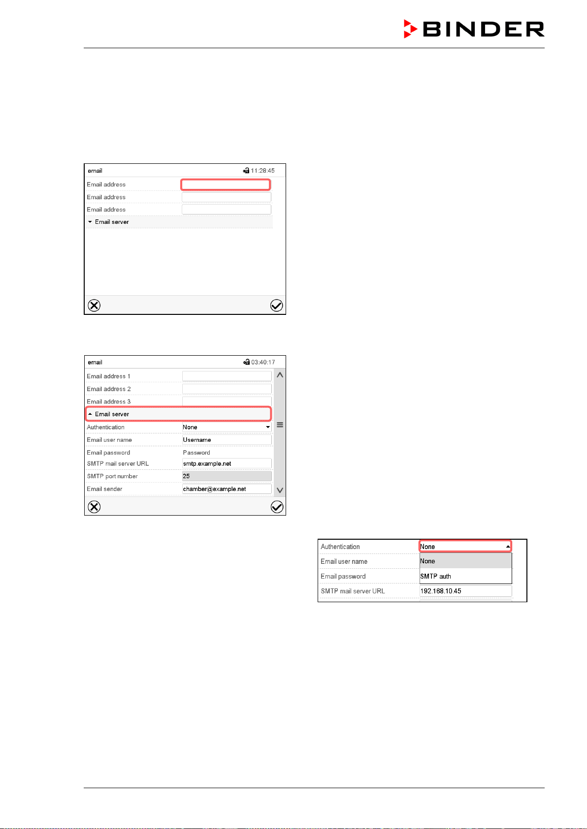
MKF / MKFT (E5) 06/2020 page 104/176
14.5.4 E-Mail
As soon as an alarm was triggered, an e-mail is sent to the configured e-mail address.
Path: Main menu > Settings > Email
E-mail address entry:
“Email” submenu.
Select the desired e-mail address field and enter the
e-mail address. You can use the Keybord change
icon for entry. Confirm entry with Confirm icon.
E-mail server settings:
“Email” submenu.
Select the field “Email server” to access the settings
• In the field “Authentication” select the desired
setting “None” or “SMTP” auth“.
With the setting “SMTP auth”, you can enter a
password under “Email password”.
• Select the field “Email user name” and enter the desired user name. Confirm entry with Confirm icon.
• Select the field “SMTP mail server URL” and enter the SMPT mail server URL. Confirm entry with
Confirm icon.
• Select the field “SMTP port number” and enter the desired port number. Standard setting: “25”.
Confirm entry with Confirm icon.
• Select the field “Email sender” and enter the desired Email sender. Confirm entry with Confirm icon.
After completing the settings, press the Confirm icon to take over the entries and exit the menu, or press
the Close icon to exit the menu without taking over the entries.
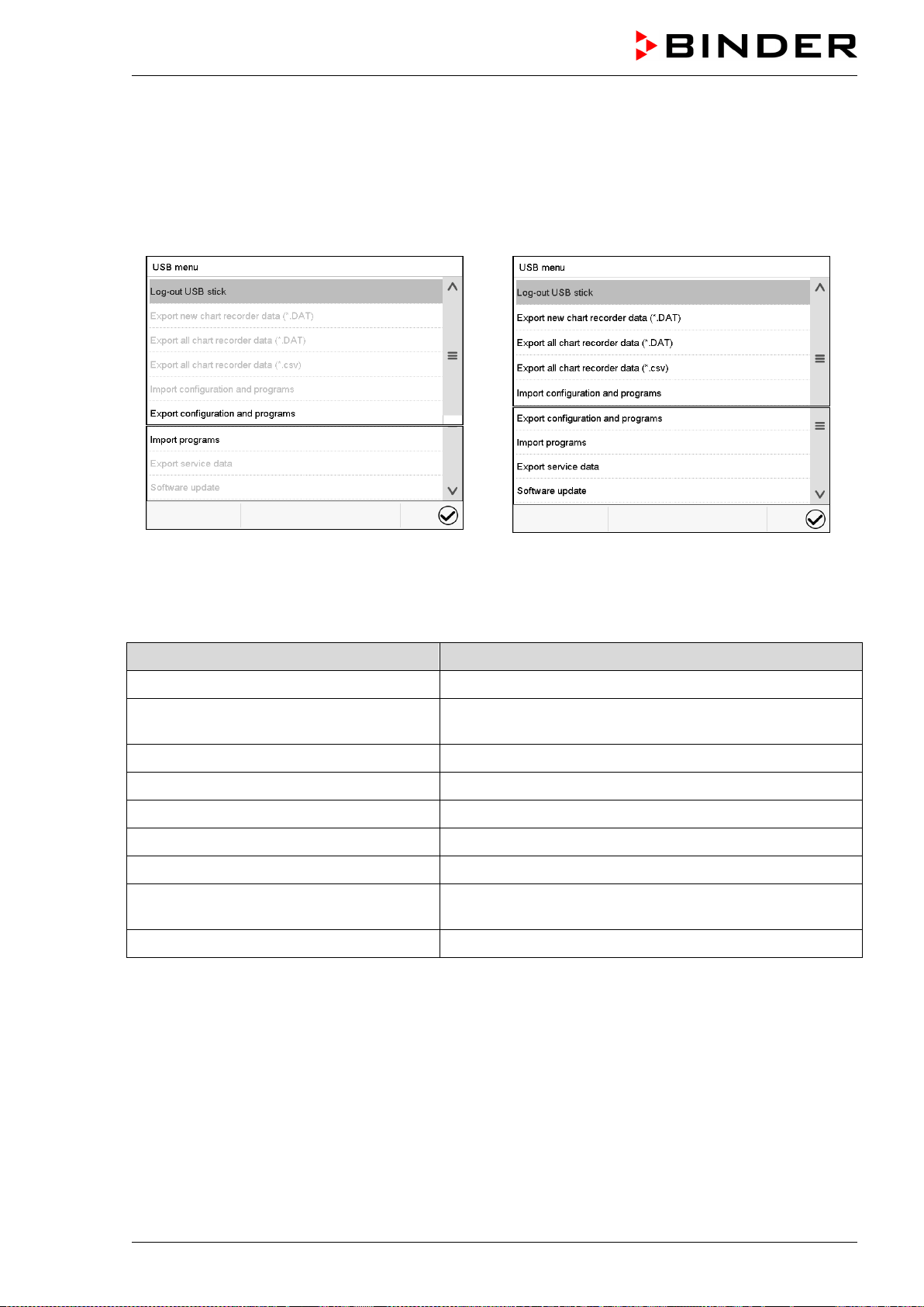
MKF / MKFT (E5) 06/2020 page 105/176
14.6 USB menu: Data transfer via USB interface
The USB port is located in the instrument box.
When you insert a USB-stick, the “USB” menu opens.
Depending on the user’s authorization level, different functions (highlighted in black) are available for the
logged-in user.
Available functions
with “User” authorization level
Available functions
with “Admin” authorization level
Function Explanation
Log-out USB stick Log-out USB stick bevor pulling it
Export new chart recorder data (*.DAT) Export chart recorder data, which have been added since
last export, in .dat format
Export all chart recorder data (*.DAT) Export all chart recorder data in .dat format
Export all chart recorder data (*.csv) Export all chart recorder data in .csv format
Import configuration and programs Import configuration and timer / time / week programs
Export configuration and programs Export configuration and timer / time / week programs
Import programs Import timer / time / week programs
Export service data
Export service data
(MKF 56: including self-test data, chap. 15.5)
Software update Controller firmware update
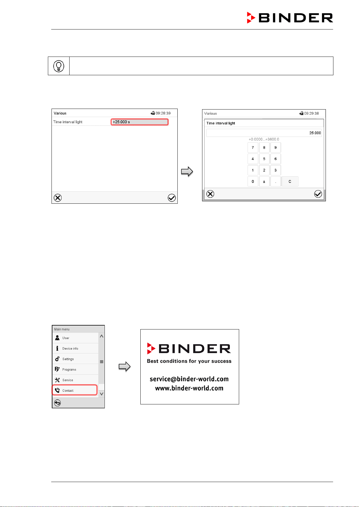
MKF / MKFT (E5) 06/2020 page 106/176
14.7 Turning off the interior lighting automatically
Press the Interior lighting icon to turn on and off the interior lighting.
Additionally. you can define in this menu the interval after which the turned-on light will turn off automati-
cally.
Path: Main menu > Settings > Various
“Various” submenu
Select the field “Time interval light”.
“Time interval light” entry menu
Enter the time in seconds after which the light
shall turn off automatically.
Setting range: 0 sec up to 3600 sec
After completing the settings, press the Confirm icon to take over the entries and exit the menu, or press
the Close icon to exit the menu without taking over the entries.
15. General information
15.1 Service contact page
Path: Main menu > Contact
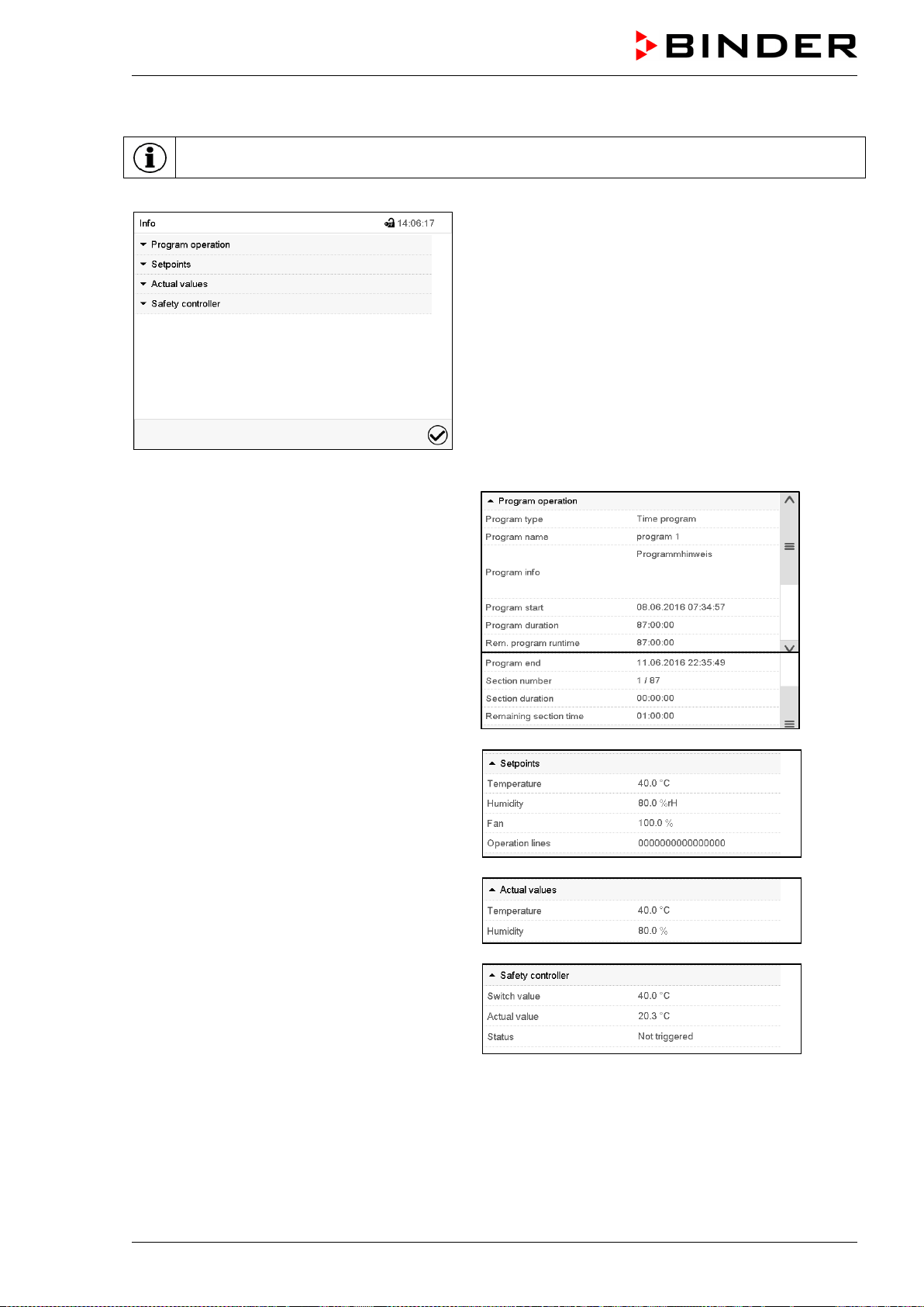
MKF / MKFT (E5) 06/2020 page 107/176
15.2 Current operating parameters
Press the Information icon to access the “Info” menu from Normal display.
“Info” menu.
Select the desired information.
• Select “Program operation” to see infor-
mation on a currently running program.
• Select “Setpoints“ to see information on the
entered setpoints and operation lines.
• Select “Actual values” to see information on
the current actual values.
• Select “Safety controller” to see information
on the safety controller status.
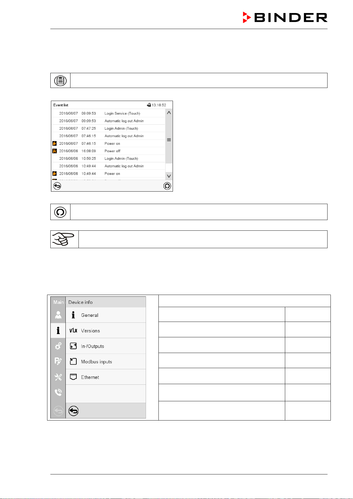
MKF / MKFT (E5) 06/2020 page 108/176
15.3 Event list
The “Event list” displays status information and errors of the current day. It enables to view the last 100
events or defective conditions of the chamber.
Press the Event list icon to access the event list from Normal display.
Event list
Press the Update icon to update the event list.
Attention: Following a modification of the language setting (chap. 14.1) or the storage inter-
val of the chart recorder (chap. 16.2) the Event list is cleared.
15.4 Technical chamber information
Path: Main menu > Device info
Chamber name and setup
Versions of CPU, I/O module and safety con-
troller
for BINDER
Service
Information on digital and analog inputs and
outputs and phase angle outputs
for BINDER
Service
Information on modbus analog and digital
inputs
for BINDER
Service
Information on Ethernet connection, MAC
address display
chap. 14.5.2
Back to main menu
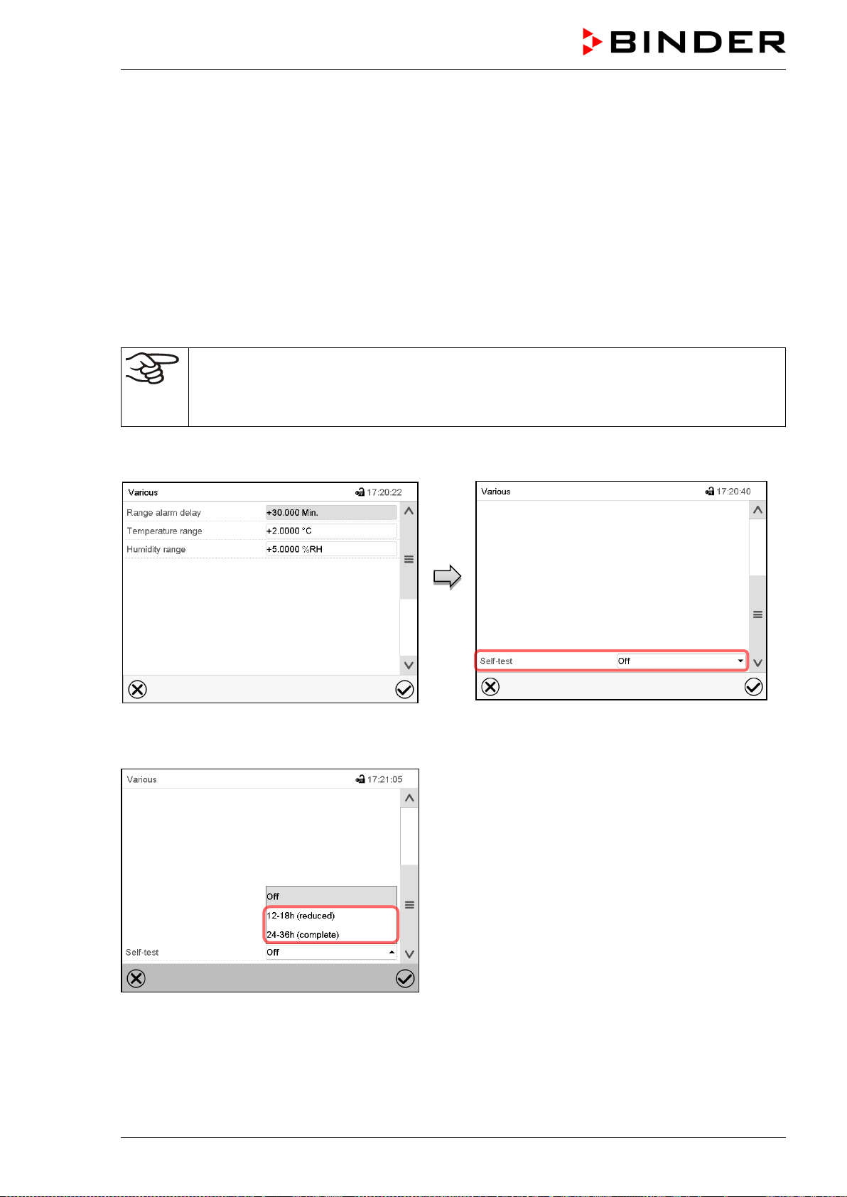
MKF / MKFT (E5) 06/2020 page 109/176
15.5 Self-test function (MK 56)
The self-test function enables an automated check of the proper chamber functioning as well as a target-
ed and reliable fault analysis. It is available with the “Master”, “Service”, and “Admin” authorization levels.
In this case, the chamber successively undergoes various defined operating states, which serves to de-
termine reproducible characteristic values. These characteristic values provide information on the perfor-
mance and precision of the individual functional systems of the chamber (e.g., heating, refrigeration, hu-
midification) of the chamber.
The results of the self-test are stored in the service recorder of the controller. You can export them using
the controller’s USB interface and send them to BINDER Service (use function “Export service data” to
USB stick, chap. 14.6). BINDER Service will evaluate the data using an analyzing tool.
Activating the self-test mode
In order to allow an optimum comparison of the determined characteristic values with the
reference characteristic values, the ambient temperature should be in the range of +22 °C
+/- 3 °C / 71.6 °F +/- 5.4 °F.
The chamber shall be unloaded (empty with standard equipment).
Path: Main menu > Settings > Various
Submenu “Various”.
Scroll all the way down to access the “Self-
test” function.
Submenu “Various”.
Select the field “Self-test”.
Submenu “Various”.
To start the self-test, select the desired test duration.
Confirm entry with Confirm icon.
Return to Normal display with the Back icon to take
over the entries.
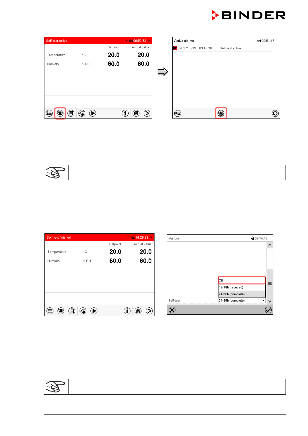
MKF / MKFT (E5) 06/2020 page 110/176
Alarm message “Self-test active”.
The self-test program is running. The indicated
set-points are non-functional.
With enabled buzzer: the buzzer sounds.
Press the Alarm icon to access the “Active
alarms” menu.
“Active alarms” menu.
The zero-voltage relay alarm output is not acti-
vated with the alarm message “Self-test active”.
Press the Reset alarm icon to mute the buzzer.
Do not open and do not turn off the chamber while self-test is running.
After an interruption of the voltage supply, the self-test restarts.
Deactivating the self-test mode
Opening the chamber door will cancel the self-test.
This step allows you to cancel the self-test or deactivate the self-test mode after the chamber has com-
pleted the self-test or the self-test has been cancelled.
Alarm message “Self-test finished”.
The chamber is in Fixed-value mode and equili-
brates to the indicated set-points.
With enabled buzzer: the buzzer sounds. Press the
Alarm icon to access the “Active alarms” menu.
Press the Reset alarm icon to mute the buzzer.
The self-test is completed. You can now deactivate
the self-test mode.
Submenu “Various”.
Select the setting “off“ to deactivate the self-test
mode after the self-test is completed or has been
cancelled by opening the door, or to cancel a run-
ning self-test.
Confirm entry with Confirm icon.
The alarm messages “Self-test active” and “Self-test finished” do not activate the zero-
voltage relay alarm output. They are listed in the Event list.
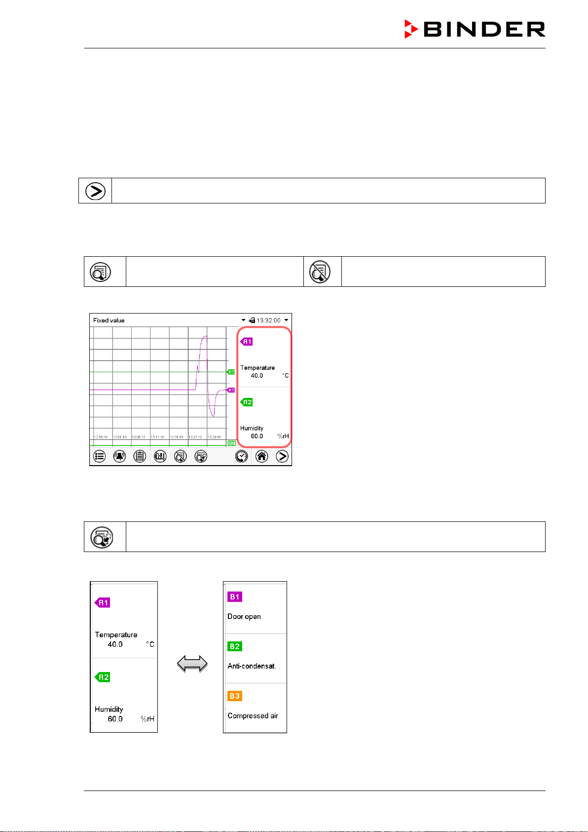
MKF / MKFT (E5) 06/2020 page 111/176
16. Chart recorder display
This view offers graphic representation of the measurement course. Data representation imitates a chart
recorder and allows recalling any set of measured data at any point of time taken from the recorded peri-
od.
16.1 Views
Press the Change view icon to access the pen recorder display.
16.1.1 Show and hide legend
Show legend
Hide legend
Press the Show legend icon to display the legend on the right side of the display
Legend shown on the right side of the display
16.1.2 Switch between legend pages
Switch legend
Press the Switch legend icon to switch between the legend pages
1
st
page
2
nd
page
Switching between the legend pages
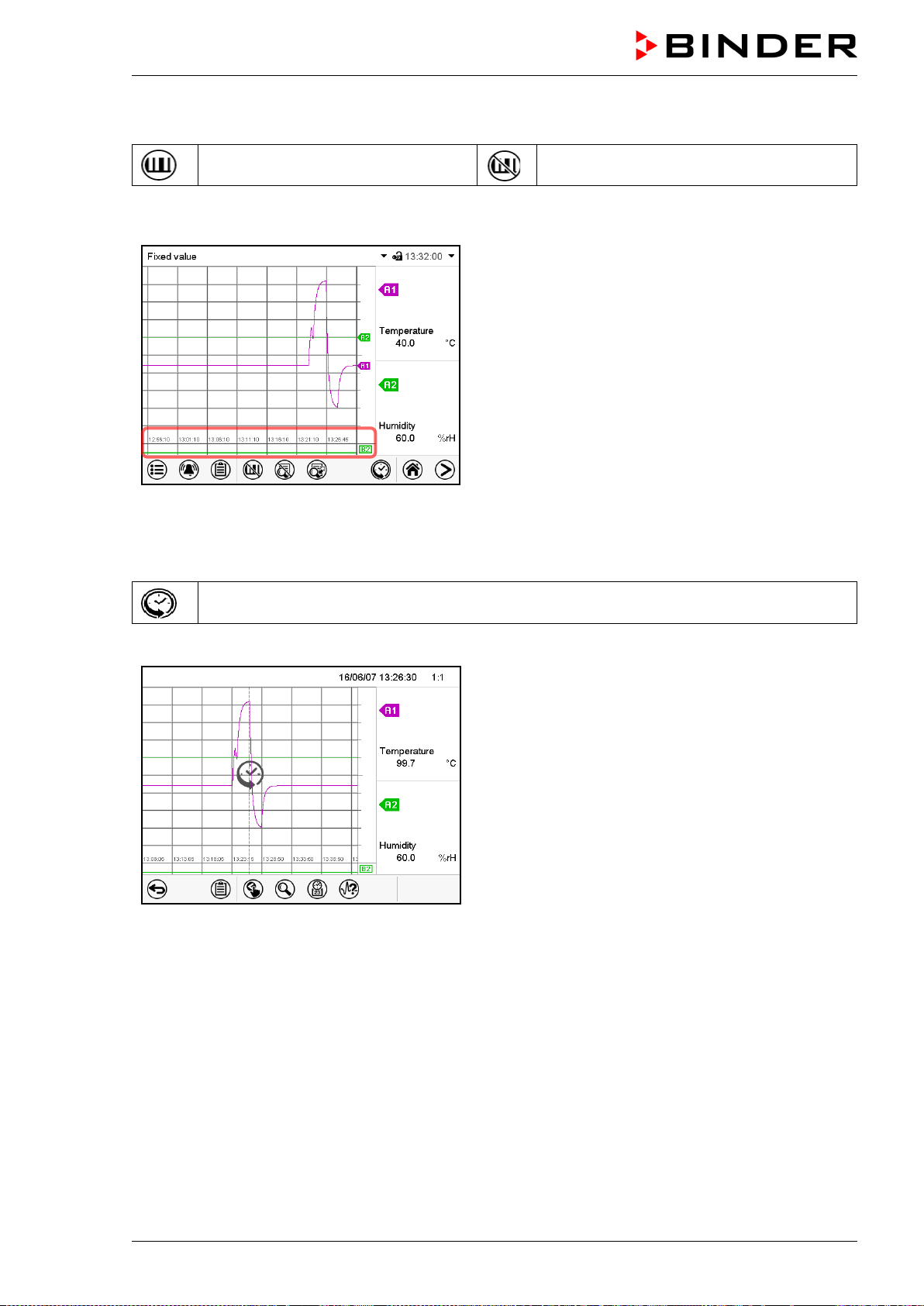
MKF / MKFT (E5) 06/2020 page 112/176
16.1.3 Show and hide specific indications
Show indications
Hide indications
Press the Show indications icon to display the indications “Door open” (B1), “Anti-condensat.” (B2),
“Compressed air” (B3)
indications “Door open” (B1), “Anti-condensat.” (B2),
“Compressed air” (B3) displayed.
16.1.4 History display
History display
Press the History display icon to change to the history display.
History display.
The chart recorder is paused. Data recording
continues in the background.
Move the central red line by tapping and holding to
the desired position.
The legend at the right side shows the values of the
current line position.
Then further icons appear:
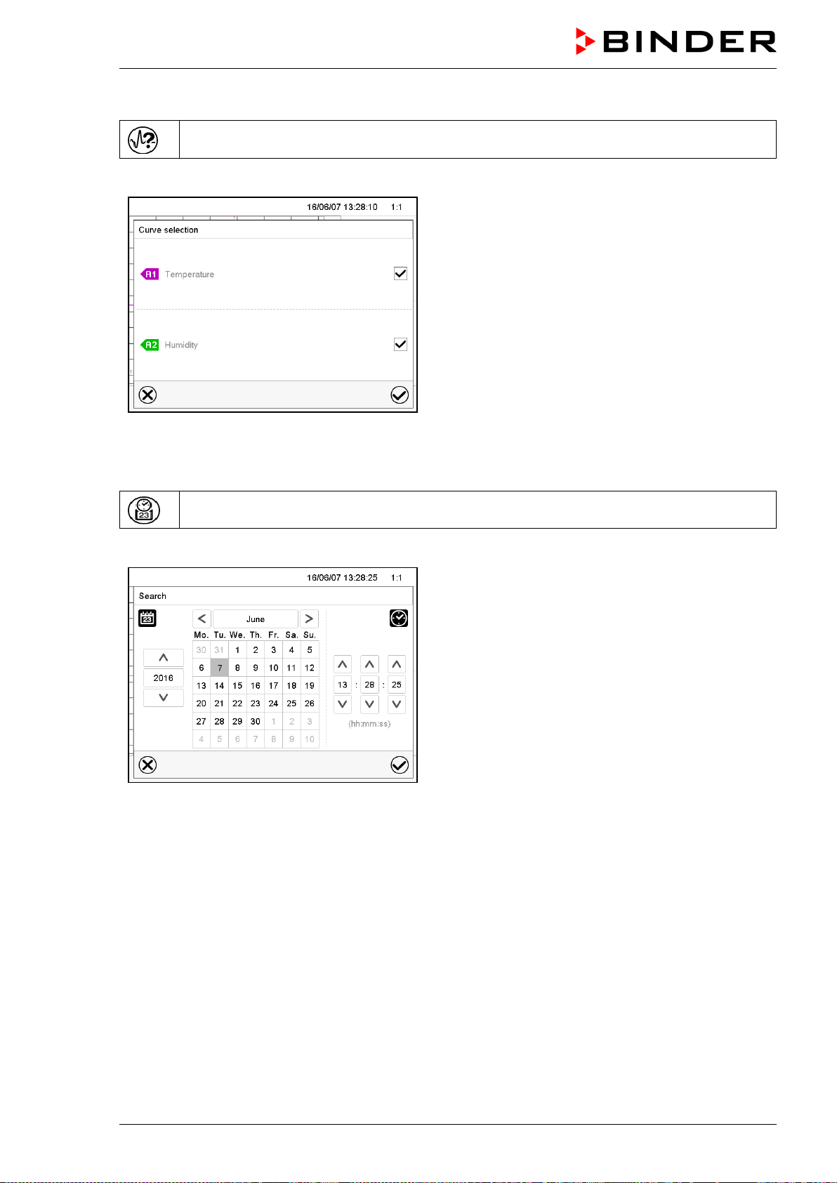
MKF / MKFT (E5) 06/2020 page 113/176
History display: Curve selection
Curve selection
Press the Curve selection icon to access the “Curve selection” submenu.
“Curve selection” submenu.
Select the curves to be displayed by checking the
checkbox of the corresponding parameter. Press the
Confirm icon
History display: Search the required instant
Search
Press the Search icon to access the “Search” submenu.
“Search” submenu.
Select the required instant by entering its date and
time and press the Confirm icon
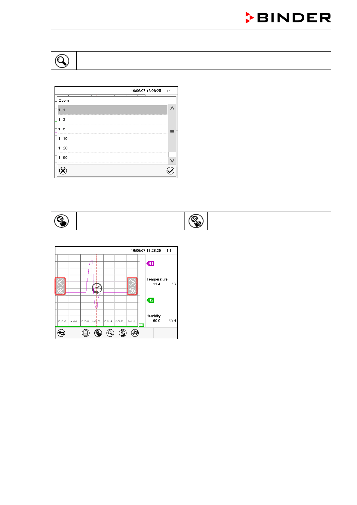
MKF / MKFT (E5) 06/2020 page 114/176
History display: Zoom function
Zoom
Press the Zoom icon to access the “Zoom” submenu.
“Zoom” submenu.
Select the zoom factor and press the Confirm icon
History display: Show and hide scroll buttons to scroll to an instant
Show scroll buttons
Hide scroll buttons
Press the Show scroll buttons icon to access the “Page selection” submenu.
“Page selection” submenu.
Scroll buttons are shown on the left and on the right.
Use them to move along the timeline.
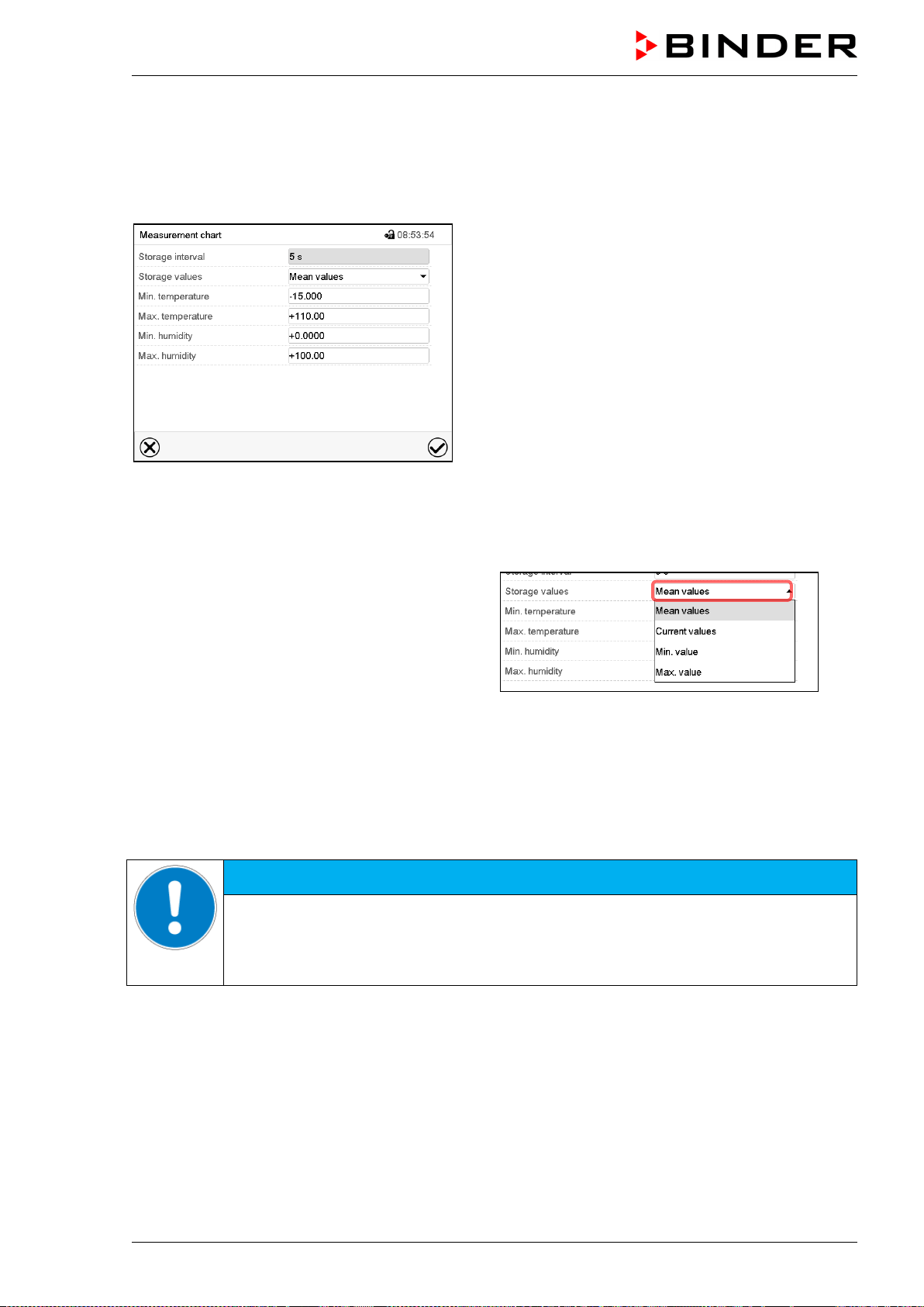
MKF / MKFT (E5) 06/2020 page 115/176
16.2 Setting the parameters
This menu allows setting the storage interval, the type of values to be shown and the scaling of the tem-
perature and humidity charts.
Path: Main menu > Settings > Measurement chart
“Measurement chart” submenu.
• Select the field “Storage interval” and enter the desired storage interval. Confirm entry with Confirm
icon.
The available presentation depends on the pre-selected storage rate. Factory setting: 60 seconds.
This means the higher the storage rate, the more precisely but shorter the data representation will be.
• In the field “Storage values” select the desired
value type to be displayed.
• For scaling the representation select the desired minimum and maximum temperature or humidity
value and enter the desired values. Temperature display range: -50 °C / -58 °F (MKF) / -80 °C /
-112 °F (MKFT) up to 180 °C / 356 °F. Humidity display range: 0% r.h. up to 100% r.h. Confirm entry
with Confirm icon.
Setting the storage rate or rescaling (minimum and/or maximum) will clear the measured-value memory
and the event list.
NOTICE
Danger of information loss when setting the storage rate or rescaling.
Data loss of measured-value memory and event list.
Change the storage rate or scaling ONLY if the previously registered data is no longer
needed.
After completing the settings, press the Confirm icon to take over the entries and exit the menu, or press
the Close icon to exit the menu without taking over the entries.
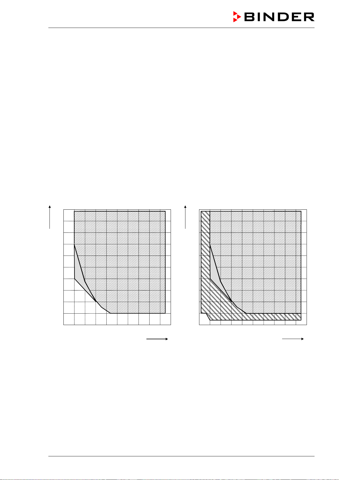
MKF / MKFT (E5) 06/2020 page 116/176
17. Humidification / dehumidification system
The chamber is equipped with a capacitive humidity sensor. This results in a regulatory accuracy of up to
+/- 2.5 % r.h. of the set point. The temperature-humidity diagrams (Figure 19) show the possible working
range for humidity.
• In the “setpoints” menu you can turn humidity control (humidification and dehumidification) on or off
with the setting “Control on/off” (chap. 6.3).
With humidity control turned off, the humidification module cools down. After activation it will take up to
20 minutes until the humidification function is fully available again. This setting is required when
operating the chamber without a water connection in order to avoid humidity alarms.
• Operation line “Humidity off” serves to turn off the humidification / dehumidification system in Fixed
value operation (chap. 7.3, time program operation (chap. 9.7.3) and week program operation (chap.
10.6.5). This allows configuring the disconnection for individual program sections.
When the humidification / dehumidification system is turned off via operation line it remain on standby
(filled and heated). Therefore it is immediately available after turning on.
When operating the chamber with activated humidity, humidity control turns off automatically at tempera-
ture set-points below 0 °C / 32 °F or above 95 °C / 203 °F. The information icon “Humidity off” is dis-
played in the screen header in Normal display. When the temperature setpoint is set back to the range
from 0 °C / 32 °F to 95 °C / 203 °F, humidity control turns on again and the information icon “Humidity off”
disappears.
0
10
20
30
40
50
60
70
80
90
100
10
20
30
40
50
60
70
80
90
100
% r.H.
°C
A
B
0
10
20
30
40
50
60
70
80
90
100
10
20
30
40
50
60
70
80
90
100
% r.
H.
°C
A
B
C
Regular chambers Chambers with optional compressed air dryer
Figure 19: Temperature-humidity diagrams
Range A: Control range of temperature and relative humidity.
Range B: Discontinuous range (no continuous operation, max. 24 hours. Observe hints on defrosting,
chap. 18)
Range C: Enlarged climatic range with optional compressed air dryer.
MKF / MKFT (E5) 06/2020 page 117/176
In climatic operation (with humidity) the preset temperature and humidity values must be situ-
ated within range A in order to achieve optimum regulation.
In the short-term (max. 24 hours), set points in the discontinuous range (range B) can also be
targeted.
On the edges of the control range (ranges A + B) the regulatory accuracies of ± 2.5 % r.H.
cannot be guaranteed.
With temperature and humidity set-points outside ranges A and B, humidification control is
automatically turned off. Humidity keeps being measured by the sensor and displayed, but
may deviate in case of condensation.
The chamber is equipped with a door heating system to prevent condensation in the door area.
Operating the chamber at humidity values > 70 % r.h. for a long period may lead to corrosion on the
housing.
NOTICE
Danger of corrosion on the housing due to condensation by excess humidity.
Damage to the chamber.
Dry the chamber completely before shut-down:
• Set the humidity to 0 % r.h. The humidity system must be activated.
• Set the temperature set point to 60 °C / 140 °F (Manual mode). Let the chamber op-
erate for approx. 2 hours with closed door. Remove the access port plugs.
• Only then, shut down the chamber
at the main power switch (1) and close the water
supply tap.
Having turned off the chamber by the main power switch (1), always close the water supply
tap.
If you operate the chamber at high humidity and then immediately turn off the chamber, the internal
wastewater collector may overflow due to the condensate. This may lead to the emergence of water at
the chamber.
NOTICE
Danger of water emerging at the chamber due to the overflow of the internal
wastewater tank by condensate.
Damage to the surroundings of the chamber.
∅ Following high humidity operation, do NOT directly turn off the chamber.
Pump off the condensate before shut-down:
•
Set the humidity to 0 % r.h. The humidity system must be activated. Operate the
chamber for at least 2 hours.
•
Only then, shut down the chamber at the main power switch (1) and close the water
supply tap.
MKF / MKFT (E5) 06/2020 page 118/176
17.1 Function of the humidifying and dehumidifying system
Humidifying system
The humidifying and dehumidifying system is located in the humidity generation module. In a cylindrical
container with a volume of approx. 2 liters an electrical resistance heating evaporates water. The water
content is kept exactly at the boiling point, and thus steam can be immediately generated in sufficient
quantity for rapid humidity increases or for compensation of humidity losses, e.g. by door openings. Con-
densation forming on the outer walls of the useable volume is led through a water drain in the outer
chamber into the wastewater can which is pumped off automatically to the wastewater pipe when re-
quired.
17.1.1 Freshwater
MKF 56: You can supply the chamber with freshwater via a water pipe or by manually filling an external
freshwater can (option, chap. 21.9). You can mount the can on the rear of the chamber or place it next to
the chamber.
MKF/MKFT 115, 240, 720: You can supply the chamber with freshwater via a water pipe or by manually
filling the internal freshwater can. It is not necessary to switch between both possibilities. When connect-
ing to a water pipe, the water can automatically fills up. The can is located behind the right door of the
humidity generation module.
In order to ensure accurate humidifying, observe the following points with regard to the
freshwater supply:
• Supply pressure 1 to 10 bar when connecting to a water pipe
• Water type: deionized (demineralized) water, see chap. 4.2.
• To ensure humidification during 24 hours even at high humidity set-points with manual wa-
ter supply, we recommend filling the freshwater can at the end of each day.
• Water intake temperature NOT below +5 °C / 41 °F and not exceeding 40 °C / 104 °F.
BINDER GmbH is NOT responsible for the water quality provided by the customer.
Any problems and malfunctions that might arise following use of water of deviating quality is
excluded from liability by BINDER GmbH.
17.1.1.1 Automatic freshwater supply via water pipe
With this type of supply, the humidity system is continuously functional.
MKF/MKFT 115, 240, 720: The correct water supply can be monitored at the internal water can, where
the water is intermediately stored also if a water pipe is connected. The correct filling level is automatical-
ly maintained at ½ to ¾ of the maximum level.
17.1.1.2 Manual fresh water supply via external freshwater can (option for MKF 56)
With this type of supply, the humidity system is functional only if the water can is sufficiently filled. Check
the filling level daily. The water reserve in the can is sufficient for a period, which may last between one
and several days, depending on the humidity demand (entered humidity set-point and number of door
openings).
For installation please refer to chap. 21.9.
MKF / MKFT (E5) 06/2020 page 119/176
17.1.1.3 Manual fresh water supply via internal freshwater can (MKF/MKFT 115, 240, 720)
With this type of supply, the humidity system is functional only if the water can is sufficiently filled. Check
the filling level daily. The water reserve in the water can is sufficient for a period, which may last between
one and several days, depending on the humidity demand (entered humidity set-point and number of
door openings). Fill the can up to the maximum level mark only. The cover of the water inlet valve must
be screwed on the freshwater connection “IN” (15) (chap. 4.2.3).
17.1.2 Wastewater
The condensation water from the interior and, with MKF/MKFT 115, 240, 720, excess freshwater in the
can (by manual excess filling or in case of fault) is collected in an internal can with a volume of approx.
1.5 liters. It is pumped off via the wastewater pipe.
Dehumidifying system
When the humidity system is activated, the chamber dehumidifies as needed in order to reach the en-
tered humidity set-point inside the Control range of temperature and relative humidity (Figure 19).
Dehumidification occurs in case of need by means of a defined dew point undershoot of several evapora-
tors of the refrigeration system. The condensate which forms is carried away as wastewater.
With temperature set-points outside the control range (hatched area in Figure 19), humidification and
dehumidification are automatically turned off. If the humidity system is turned off while there are descend-
ing temperature curves, then operation of the refrigeration system may cause dehumidification of the
charging material.
With humidity set-points outside the control range (hatched area in Figure 19), or with entry of set-point
0 % r.h., the humidification and dehumidification system is turned off even if the humidity system is acti-
vated.
For error indications concerning water supply and humidity system, see chap.11.1.3 and 23.3
18. Defrosting at refrigerating operation
BINDER alternating climate chambers are very diffusion-proof. To ensure high temperature precision
there is no automatic cyclic defrosting device. However, at very low temperatures, the moisture in the air
can condense on the evaporator plates leading to icing.
Always close the door properly.
Operation with temperature set-points above +5 °C / 41 °F at an ambient temperature of 20 °C /
68 °F:
The air defrosts the ice cover automatically. Defrosting is continually performed.
Operation with temperature set-points below +5 °C / 41 °F or in the discontinuous range (chap.
17):
The evaporator can cover with ice. Defrost the chamber manually.
With temperature set-points below +5 °C / 41 °F, regularly defrost the chamber manually:
• Set the humidity to 0 % r.h. The humidity system must be activated.
• Set the temperature to 60 °C / 140 °F (Manual Mode).
• Let the chamber operate for approx. 1 hour with the door closed.
Too much ice on the evaporator is noticeable by reduced refrigerating performance.
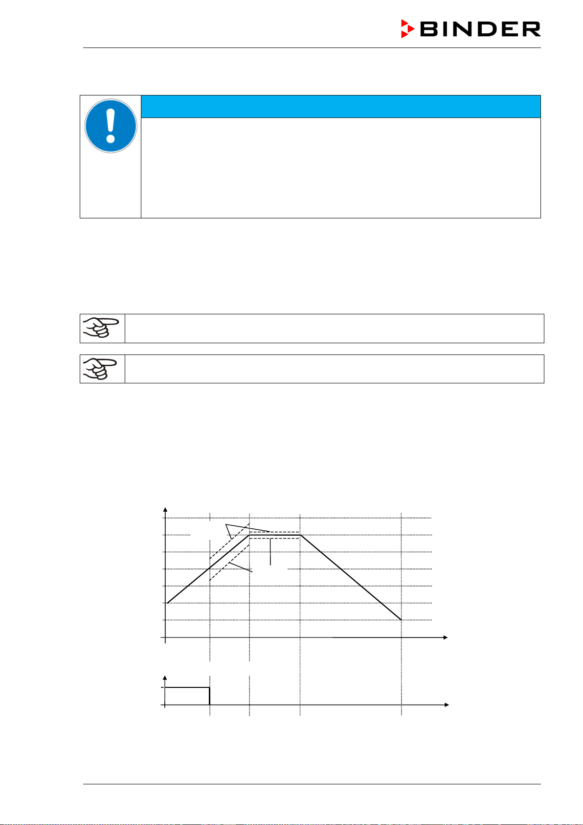
MKF / MKFT (E5) 06/2020 page 120/176
When turning off the chamber following prolonged refrigerating below +5 °C / 41 °F, there is danger of
overflowing due to uncontrolled defrosting of icing on the evaporator.
NOTICE
Danger of overflowing due to uncontrolled defrosting of icing on the evaporator.
Damage to the surroundings of the chamber.
After several days of refrigerating below +5 °C / 41 °F:
∅ Do NOT directly turn off the chamber.
Manually defrost the chamber (see description above).
Then, shut down the chamber at the main power switch (1) and close the tap of the
water supply.
19. Anti-condensation protection via operation line
When operating the chamber without humidification, the anti-condensation protection condensates the
chamber humidity at the coldest point in order to avoid the samples becoming wet from condensation.
Anti-condensation protection is performed by the evaporator and can be programmed On/Off via opera-
tion line “Anti-condensation” in Fixed value and program modes.
Use the anti-condensation protection only if absolutely necessary to prevent condensation on
the charging material.
Use the anti-condensation protection only when operating the chamber without humidification.
When the anti-condensation protection is enabled the refrigeration machine keeps operating within warm-
ing-up phases (On = refrigeration machine operating, Off = refrigeration machine off).
• If possible, use the anti-condensation protection only during warm-up phases. If necessary, you
can also activate it during hold phases.
• Do NOT use the anti-condensation protection above a temperature set-point of +20 °C / 68°F
maximum.
To obtain optimal warming results without condensation on the samples, program a heating gradient of
approx. 0.5 °C/min.
Example:
W/°C
t/min.
00
01
02
03
-40
-20
0
20
40
60
80
120
180
380
04
ON
OFF
t/min.
Minimum
tolerance
Maximum
tolerance
Operation line “Anti-condensation”
Depending on size, material, and shape of the charging material and on the heating-up rate, condensa-
tion may form despite the activated anti-condensation protection. This condensation is, however, reduced
compared to the state without anti-condensation protection.
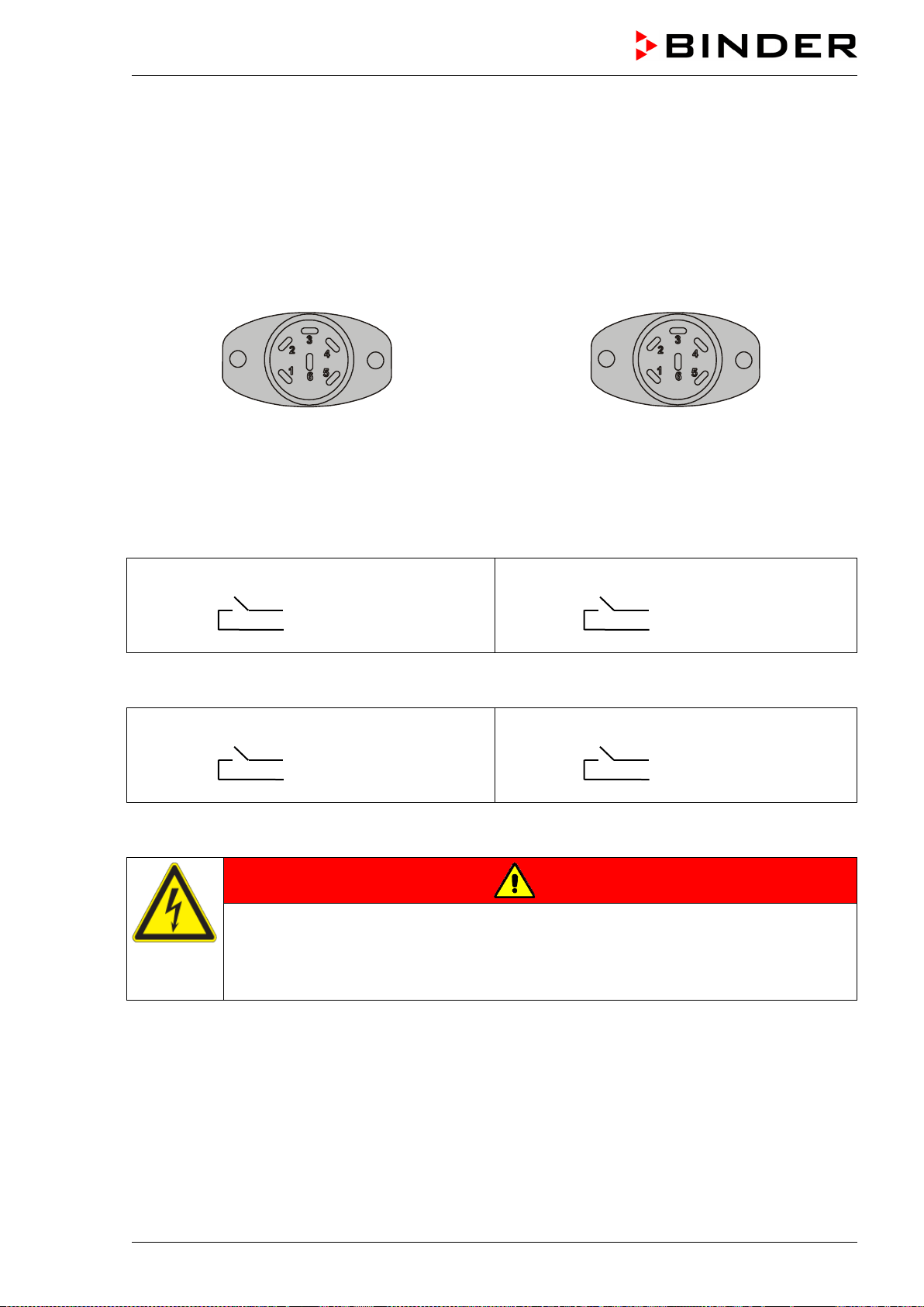
MKF / MKFT (E5) 06/2020 page 121/176
20. Zero-voltage switching outputs via operation lines
The chambers are regularly equipped with four zero-voltage switching outputs (DIN sockets (7) and (8)
located in the lateral control panel).
The operation lines serve to switch any device connected to the zero-voltage relay output. They can be
programmed On/Off in Fixed value and program modes.
Connection for operation lines “Switching output 1” and “Switching output 2” occurs via DIN socket (7),
connection for operation lines “Switching output 3” and “Switching output 4” via DIN socket (8) in the lat-
eral control panel:
OUTPUT TRACK 1+2
24V/MAX.2,5A
OUTPUT TRACK 3+4
24V/MAX.2,5A
Figure 20: Pin configuration of DIN sockets (7) left and (8) right
DIN socket (7):
Operation line “Switching output 1” Operation line “Switching output 2”
Pin 1: Pin
Pin 2: Make
Pin 4: Pin
Pin 5: Make
DIN socket (8):
Operation line “Switching output 3” Operation line “Switching output 4”
Pin 1: Pin
Pin 2: Make
Pin 4: Pin
Pin 5: Make
Maximum loading capacity of the switching contacts: 24V AC/DC – 2.5 A
DANGER
Electrical hazard through overload of contacts.
Deadly electric shock. Damage to the switching contacts and connection socket.
∅ Do NOT exceed the maximum switching load of 24V AC/DC – 2.5A.
∅ Do NOT connect any devices with a higher loading capacity.
MKF / MKFT (E5) 06/2020 page 122/176
21. Options
21.1 APT-COM™ 4 Multi Management Software (option)
The chamber is regularly equipped with an Ethernet interface (5) that can connect the BINDER APT-
COM™ 4 Multi Management Software. The MAC Address is indicated in the “Device info” controller menu
(chap. 14.5.2.2). The actual temperature and humidity values are given at adjustable intervals. Program-
ming can be performed graphically via PC. Up to 100 chambers can be cross-linked. For further infor-
mation on networking, please refer to the APT-COM™ 4 operating manual.
APT-COM™ 4 Basic Edition is included with the chamber. APT-COM™ 4 is available for download on the
BINDER website. Upon registering the chamber, you will receive a license key with which you can acti-
vate the functionality of the Basic Edition for your downloaded version. For further information see chap.
27.2.
21.2 RS485 interface (option)
With this option, the chamber is equipped with an additional 2-wire RS485 serial interface (5a) that can
connect the BINDER APT-COM™ 4 Multi Management Software. The actual temperature and humidity
values are given at adjustable intervals. For further information, please refer to the APT-COM™ 4 operat-
ing manual.
21.3 Data logger kits (option)
BINDER Data Logger Kits offer an independent long-term measuring system for temperature and humidi-
ty, available for different temperature ranges. According to the selected kit, the Data Logger can measure
and record also the ambient temperature and humidity values via a second multi-function sensor.
BINDER Data Loggers are equipped with a keyboard and a large LCD display, alarm functions and a
real-time function. Measurement data are recorded in the Data Logger and can be read out after the
measurement via the RS232 interface of the Data Logger. It offers a programmable measuring interval
and permits storing up to 64000 measuring values. Reading out is done with the Data Logger evaluation
software. You can give out a combined alarm and status protocol directly to a serial printer.
Data Logger Kit T 220: Sensor for chamber temperature: Temperature range -90 °C / -130 °F up to
+220 °C / 428 °F .
Data Logger Kit TH 100: Multi-function sensor for chamber temperature and humidity: Temperature
range -40 °C / -40 °F up to +100 °C / 212 °F , humidity range 0% r.h. up to 100% r.h.
Data Logger Kit TH 100/70: Multi-function sensor for chamber temperature and humidity: Temperature
range -40 °C / -40 °F up to +100 °C / 212 °F, humidity range 0% r.h. up to 100% r.h. Multi-function sensor
for ambient temperature and humidity: Temperature range -40 °C / -40 °F up to 70 °C / 158 °F, humidity
range 0% r.h. up to 100% r.h.
For detailed information on installation and operation of the BINDER Data Logger, please
refer to the mounting instructions Art. No. 7001-0204 and to the original user manual of the
manufacturer, supplied with the data logger.
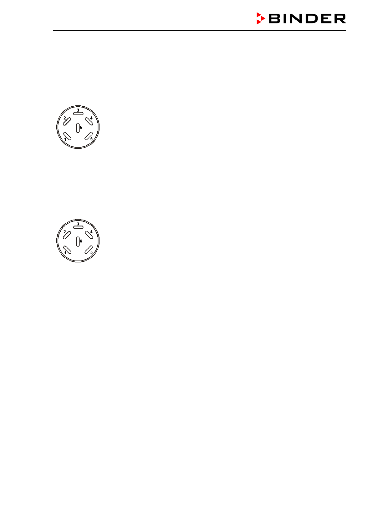
MKF / MKFT (E5) 06/2020 page 123/176
21.4 Analog outputs for temperature and humidity (option)
With this option, the chamber is equipped with analogue outputs 4-20 mA for actual value and set-point
value of temperature and of humidity. These outputs allow transmitting data to external data registration
systems or devices.
The connection “analog outputs for temperature” is realized as a DIN socket (9) in the lateral control pan-
el as follows:
ANALOG OUTPUT TEMPERATURE 4-20 mA DC
PIN 1: Temperature actual value –
PIN 2: Temperature actual value +
PIN 4: Temperature set-point value –
PIN 5: Temperature set-point value +
MKF: Temperature range: -40 °C / -40 °F up to +180 °C / -356 °F
MKFT: Temperature range: -70 °C / -94 °F up to +180 °C / -356 °F
A suitable DIN plug is enclosed.
Figure 21: Pin allocation of DIN socket (9) for option analog outputs for temperature
The connection “analog outputs for humidity” is carried out as a DIN socket (10) in the lateral control pan-
el as following:
ANALOG OUTPUT HUMIDITY 4-20 mA DC
PIN 1: Humidity actual value –
PIN 2: Humidity actual value +
PIN 4: Humidity set-point value –
PIN 5: Humidity set-point value +
Humidity range: 0 % r.h. up to 100 % r.h.
A suitable DIN plug is enclosed.
Figure 22: Pin allocation of DIN socket (10) for option analog outputs for humidity
21.5 Compressed air connection (option)
This option permits directly connecting compressed air to the chamber.
Requirements for the compressed air supplied directly to the chamber
• Quality of the air: DIN ISO 8573-1:2010 [2:2:1]
• Supply pressure: 6-8 bar domestic connection
If a different connection pressure is required, please contact BINDER INDIVIDUAL Customized Solu-
tions.
• Permissible temperature: +10 °C / 50 °F up to +50 °C / 122 °F.
• Air requirement: 15 m³/h (at normal pressure)
• Connection:
Connection is established to the coupling connector (20) in the rear panel : Standard quick acting closure
socket for compressed air, nominal width 7.85 mm / 0.31 in.
Activation:
Operation line “Compressed air valve” serves to open the solenoid valve of the compressed air connec-
tion (20).
MKF / MKFT (E5) 06/2020 page 124/176
21.6 Controlled compressed air dryer (option)
This option permits stronger dehumidification and thus the chamber can obtain lower humidity value, see
modified temperature-humidity diagram (chap. 17). Chambers with a compressed air dryer are particularly
suitable for compliance with the common automotive standards.
Requirements for the compressed air supplied to the compressed air dryer:
• Quality of the air: DIN ISO 8573-1:2010 [4:4:3]
No water must enter into the compressed air dryer (danger of destruction)
No oil must enter into the compressed air dryer. Oil is the main cause of damage for the
compressed air dryer and shortens its life span.
• Supply pressure: 6-8 bar domestic connection
If a different connection pressure is required, please contact BINDER INDIVIDUAL Customized Solu-
tions.
• Permissible temperature: +10 °C / 50 °F up to +50 °C / 122 °F.
• Air requirement: 15 m³/h (at normal pressure)
Connection:
The compressed air dryer is supplied ready assembled.
Connection of the compressed air supply is established to the coupling connector (20) in the rear panel:
Standard quick acting closure socket for compressed air, nominal width 7.85 mm / 0.31 in.
Activation:
Operation line “Compr. air dryer” of the controller serves to activate the compressed air dryer.
Then operation line “Compressed air valve” serves to open the solenoid valve of the compressed air con-
nection (20).
To turn on or off the operation lines (control contacts), please refer to chap. 7.3 for fixed value operation,
9.7.3 for time program operation, 10.6.5 for week program operation.
0 = operation line activated, 1 = operation line deactivated.
Note:
Automatic regeneration in a 2-minute interval is required for the function of the compressed air dryer. As
this happens, a small amount of compressed air is suddenly released into the environment, what is asso-
ciated with some noise.
The desiccant cartridges must be replaced after no more than 17,500 operating hours or 2 years. The
filter must be replaced after a maximum of 8,760 hours or 1 year. We recommend an annual maintenance
interval.
An exchange is also necessary when the status display on the rear panel is lit or flashes in yellow. Check
the status display approx. once per month.
Normal operating state
Filter elements and desiccant cartridges must be replaced. Contact BINDER Service
Alarm. Contact BINDER Service
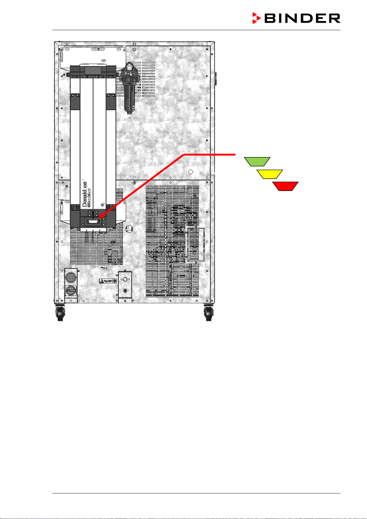
MKF / MKFT (E5) 06/2020 page 125/176
Status display
Figure 23: Rear chamber view with optional compressed air dryer (example: MKFT 115)
21.7 Water cooling (option for MKF 56, 115, 240, 720, and MKFT 720)
The water cooling serves to cool the chamber instead of the air cooling and reduces the heat, which is
emitted to the ambient air during cooling operation.
MKF 56, 115, 240: The water cooling option allows to select between air cooling and water cooling. The
water cooling is turned on via the switch (3) in the lateral control panel. When it is turned off, the air cool-
ing is active.
MKF / MKFT 720: With the water cooling option, the chamber always cools with the water cooling.
Retrofitting by the manufacturer is possible: The chamber must be returned to the BINDER factory for
installation.
You can supply the chamber’s humidity system with freshwater and drain the wastewater via a water pipe
or manually with the internal water cans, like with the regular chamber. With the optional water cooling,
the chamber is equipped with two additional connections for the inlet and outlet of the cooling water.
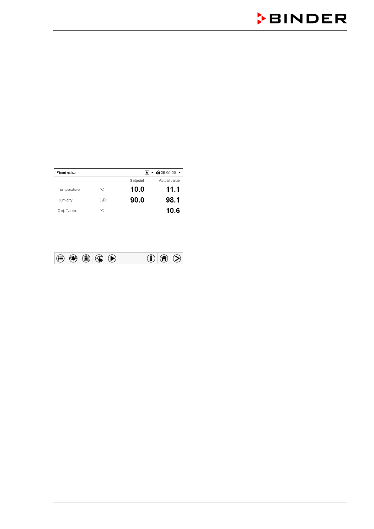
MKF / MKFT (E5) 06/2020 page 126/176
Water connections
With the optional water cooling the chamber is supplied with cooling water via a freshwater pipe (max.
inlet temperature: 10 °C / 50 °F).
• Connection of cooling water inlet: please refer to chap. 4.4.
• Connection of cooling water outlet: please refer to chap. 4.3.
21.8 Object temperature display with flexible Pt 100 temperature sensor (option)
The object temperature display enables the determination of the actual temperature of the charging mate-
rial during the whole process. The object temperature is measured via a flexible Pt100 temperature sen-
sor and can be viewed on the controller display. You can immerse the sensor top protective tube of the
flexible Pt 100 into liquid substances.
Normal display with object temperature display
(sample values)
The object temperature data are put out together with the data of the temperature controller to the inter-
face as second measuring channel and can be documented by the APT-COM™ 4 Multi Management
Software (option, chap. 21.1) developed by BINDER.
Technical data of the Pt 100 sensor:
• Three-wire technique
• Class B (DIN EN 60751)
• Temperature range up to 320 °C / 608°F
• Stainless steel protective tube with a length of 45 mm / 1.78 in, material no. 1.4501
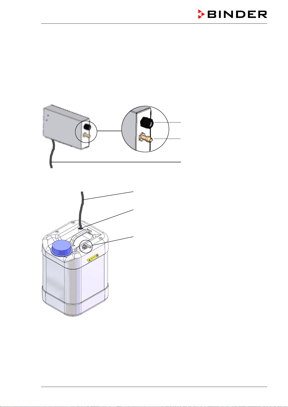
MKF / MKFT (E5) 06/2020 page 127/176
21.9 External freshwater and wastewater cans (option for MKF 56)
If no suitable in-house water connection is available, you can manually supply water by filling the optional
external freshwater can. There is an additional external water can for the waste water. The volume of
each can is 20 liters / 0.71 cu.ft.
You can place the cans next to the chamber.
21.9.1 Connecting the freshwater can and the pump
The water pump is attached to the MKF 56 housing with magnets.
Cable connection (21)
Freshwater hose connection (22)
Freshwater supply hose
Figure 24: Water pump on the chamber rear panel
Freshwater supply hose to the pump
Inlet opening (26) for the freshwater supply hose
Hose connection (24) of the freshwater can
with wastewater recycling (chap. 21.9.3)
Figure 25: Freshwater can
Hose between the pump and the freshwater can
The freshwater supply hose is located at the bottom of the pump. Lead it through the inlet opening (26)
into the freshwater can. The end of the hose must be placed at the bottom of the can.
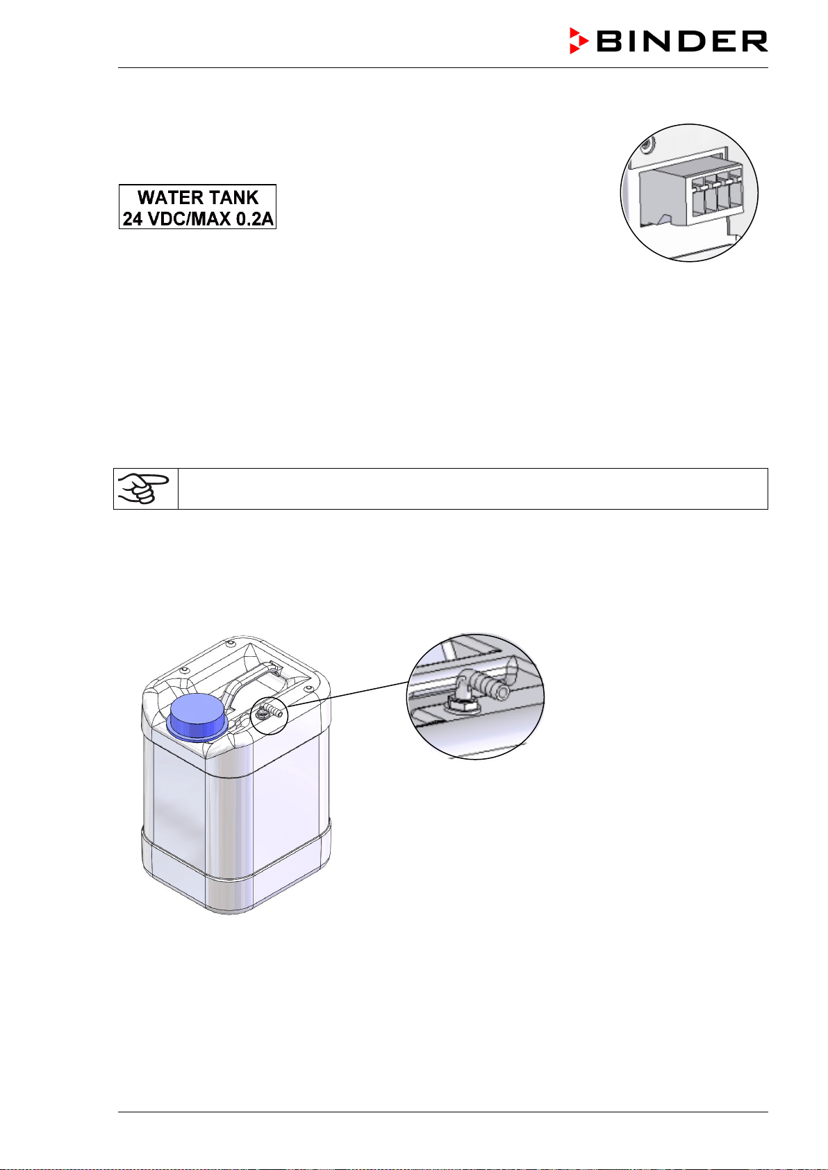
MKF / MKFT (E5) 06/2020 page 128/176
Cable connection between the pump and the climatic chamber
Connect the cable plug from the cable connection (21) on the pump to the
socket (18) at the rear of the chamber.
The socket (18) is marked with a sticker:
Socket (18)
Hose connections between the pump and the climatic chamber
Plug the freshwater hose into the hose connection (22) on the pump and secure it with a hose clamp. You
can use a part of the standard supplied water hose.
Screw the hose nozzle (brass) to the free edge of the hose and screw it directly onto the freshwater con-
nection “IN” (15) at the rear of the chamber.
When the freshwater can is empty, the message “Freshwater supply” will be displayed on the controller
(chap. 11.1.3), the buzzer sounds, and the humidification module turns off. After acknowledging the
alarm, the humidification module tries to fill up and start operating.
To guarantee humidification during 24 hours even at high humidity set-points with manual
water supply, we recommend filling the freshwater can (option) at the end of each day.
21.9.2 Connecting the wastewater can
Hose connection
Plug the wastewater hose to the hose connection (23) of the wastewater can and secure it with a hose
clamp. You can use a part of the standard supplied water hose.
Hose connection (23)
of the wastewater can
Figure 26: Wastewater can
Plug the free hose edge to the wastewater connection “OUT” (14) at the rear of the chamber and secure it
with a hose clamp.
For emptying the wastewater can disconnect the hose first.
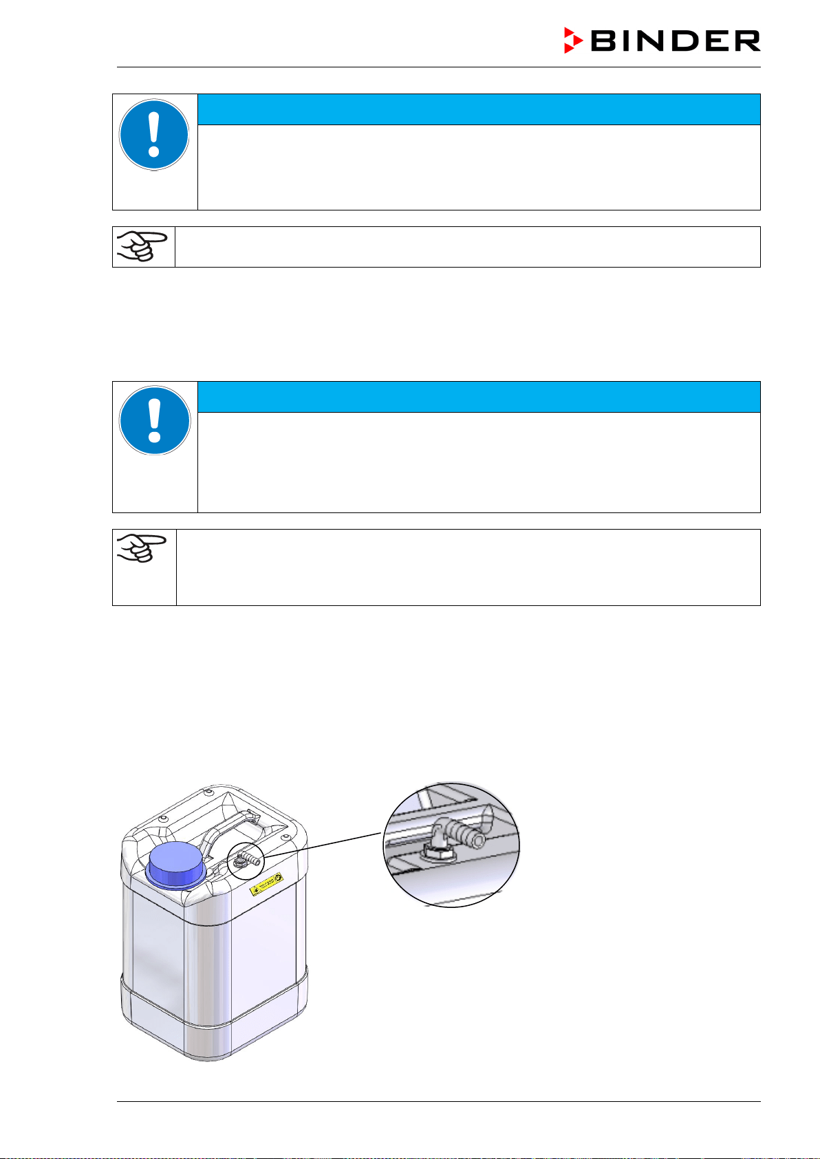
MKF / MKFT (E5) 06/2020 page 129/176
NOTICE
Danger of overflow of the wastewater can.
Damage to the surroundings of the chamber.
Regularly check the filling level of the wastewater can.
Always empty the wastewater can in a timely manner before it is full.
Bringing a source of humidity into the inner chamber may increase wastewater production.
Regularly check the filling level of the wastewater can.
21.9.3 Connecting with wastewater recycling
When the chamber interior is clean, you can reuse the wastewater from the chamber. Connect the
wastewater connection “OUT” (14) of the chamber with the hose connection (24) of the freshwater can.
The wastewater can is not used in this case.
NOTICE
Danger of soiling of the vapor humidification system.
Damage to the chamber.
Make sure to reuse wastewater ONLY with a clean chamber interior.
In case of soiling / contamination of the interior, conduct the wastewater to the
wastewater connection or use the wastewater can.
BINDER GmbH is NOT responsible for the water quality at the user’s site, especially when
reusing wastewater.
Any problems and malfunctions that might arise following use of wastewater are excluded
from liability by BINDER GmbH.
Cable connection between the pump and the climatic chamber
Connect the cable plug from the cable connection (21) on the pump to the socket (18) at the rear of the
chamber as described in chap. 21.9.1.
Hose connection between the wastewater hose of the climatic chamber and the freshwater can
Plug the wastewater hose into the hose connection (24) of the freshwater can and secure it with a hose
clamp. You can use a part of the standard supplied water hose.
Plug the free hose edge to the wastewater connection “OUT” (14) at the rear of the chamber and secure it
with a hose clamp.
Hose connection (24)
of the freshwater can
Figure 27: Freshwater can
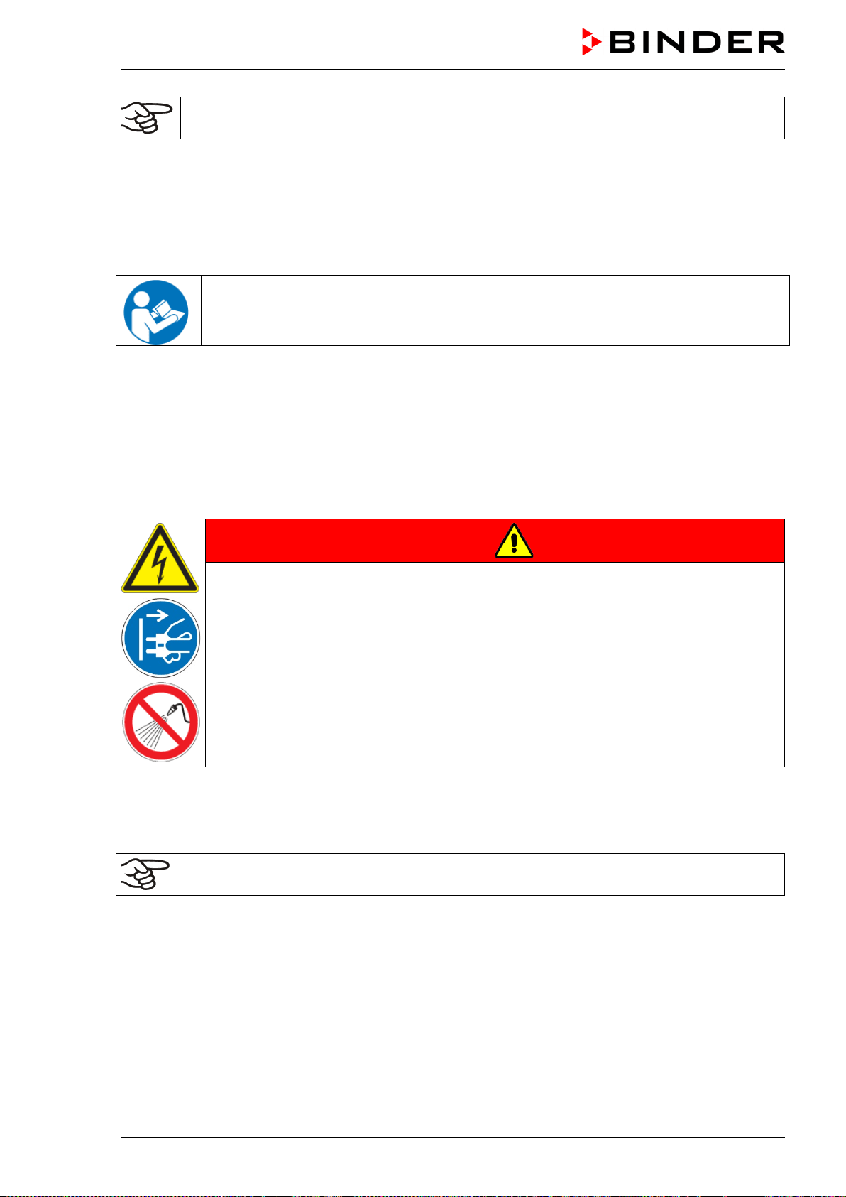
MKF / MKFT (E5) 06/2020 page 130/176
Bringing a source of humidity into the inner chamber may increase wastewater production.
Regularly check the filling level of the freshwater can.
21.10 BINDER Pure Aqua Service (option)
The optional BINDER water treatment system (disposable system) serves to treat tap water. The lifetime
depends on water quality and the amount of treated water. The measuring equipment to assess the water
quality is reusable.
For detailed information on operating the water treatment system BINDER Pure Aqua Ser-
vice and its function, please refer to the operating manual, supplied with BINDER Pure Aq-
ua Service.
22. Cleaning and decontamination
Clean the chamber after each use in order to prevent potential corrosion damage by ingredients of the
loading material.
Prior to renewed startup, allow the chamber to completely dry after all cleaning and decontamination
measures.
DANGER
Electrical hazard by water entering the chamber.
Deadly electric shock.
∅ Do NOT spill water or cleaning agents over the inner and outer chamber surfaces.
∅ Do NOT put ANY cleaning aids (cloth or brush) into slots or openings on the chamber.
Before cleaning, turn off the chamber at the main power switch and disconnect the
power plug. Let the chamber cool down to ambient temperature.
Completely dry the chamber before turning it on again.
22.1 Cleaning
Disconnect the chamber from the power supply before cleaning. Pull the power plug.
The interior of the chamber must be kept clean. Thoroughly remove any residues of test mate-
rial.
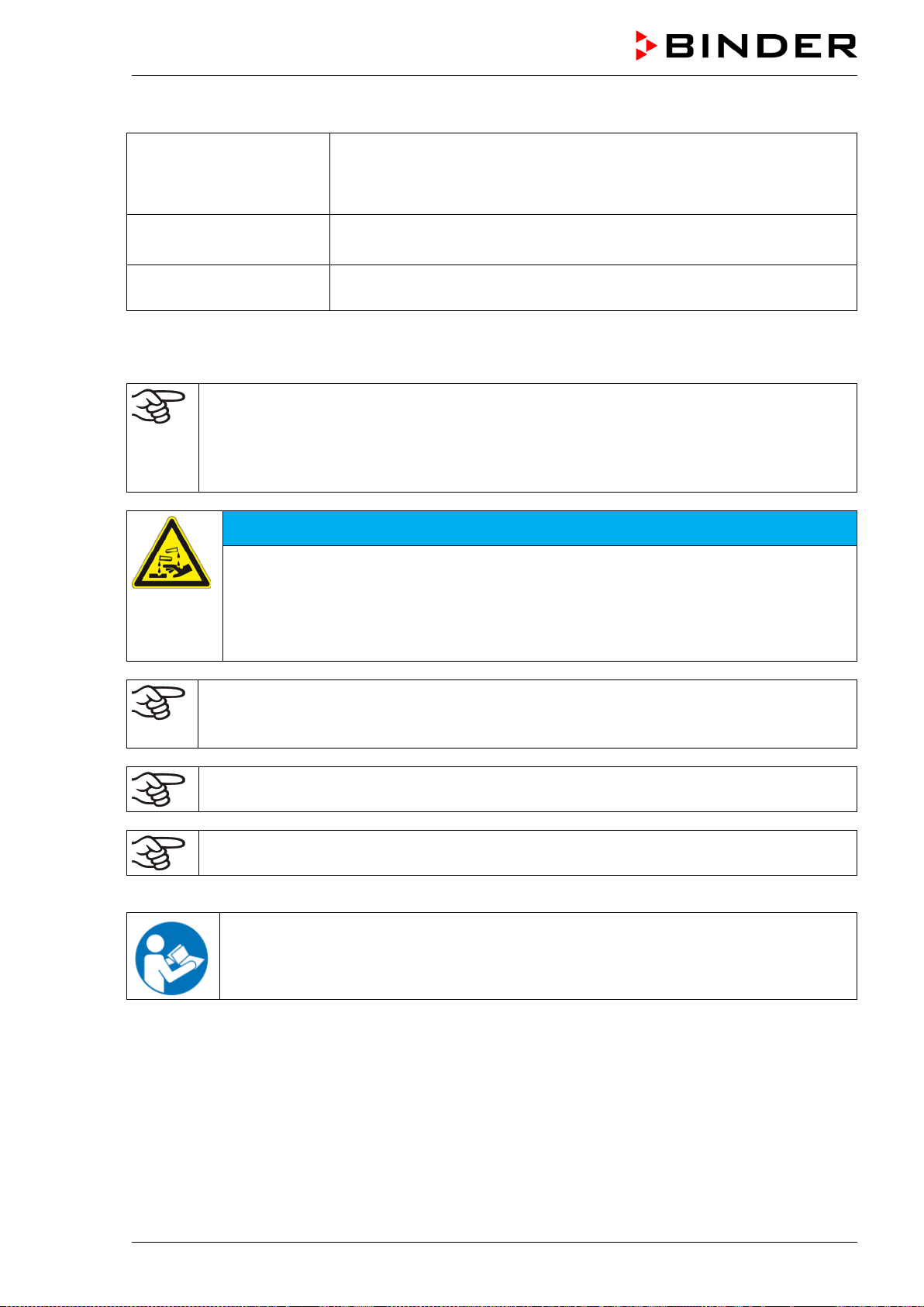
MKF / MKFT (E5) 06/2020 page 131/176
Wipe the surfaces with a moistened towel. In addition, you can use the following cleaning agents:
Exterior surfaces
inner chamber
racks
door gaskets
Standard commercial cleaning detergents free from acid or halides.
Alcohol based solutions.
We recommend using the neutral cleaning agent Art. No. 1002-0016.
Instrument panel Standard commercial cleaning detergents free from acid or halides.
We recommend using the neutral cleaning agent Art. No. 1002-0016.
Zinc coated hinge parts
rear chamber wall
Standard commercial cleaning detergents free from acid or halides. Do
NOT use a neutral cleaning agent on zinc coated surfaces.
Do not use cleaning agents that may cause a hazard due to reaction with components of the device or
the charging material. If there is doubt regarding the suitability of cleaning products, please contact
BINDER service.
We recommend using the neutral cleaning agent Art. No. 1002-0016 for a thorough cleaning.
Any corrosive damage that may arise following use of other cleaning agents is excluded from
liability by BINDER GmbH.
Any corrosive damage caused by a lack of cleaning, is excluded from liability by BINDER
GmbH.
NOTICE
Danger of corrosion by using unsuitable cleaners.
Damage to the chamber.
∅ Do NOT use acidic or chlorine cleaning detergents.
∅ Do NOT use a neutral cleaning agent on other kind of surfaces e.g., the zinc coated
hinge parts or the rear chamber wall.
For surface protection, perform cleaning as quickly as possible.
After cleaning completely remove cleaning agents from the surfaces with a moistened towel.
Let the chamber dry.
Soapsuds may contain chlorides and must therefore NOT be used for cleaning.
With every cleaning method, always use adequate personal safety controls.
Following cleaning, leave the chamber door open or remove the access port plugs.
The neutral cleaning agent may cause health problems in contact with skin and if ingested.
Follow the operating instructions and safety hints labeled on the bottle of the neutral clean-
ing agent.
MKF / MKFT (E5) 06/2020 page 132/176
Recommended precautions: To protect the eyes use sealed protective goggles. Wear gloves. Suitable
protective gloves with full contact: butyl or nitrile rubber, penetration time >480 minutes.
CAUTION
Danger of chemical burns through contact with skin or ingestion of the
neutral cleaning agent.
Skin and eye damage. Environmental damage.
∅ Do not ingest the neutral cleaning agent. Keep it away from food and
beverages.
∅ Do NOT empty the neutral cleaning agent into drains.
Wear protective gloves and goggles.
Avoid skin contact with the neutral cleaning agent.
22.2 Decontamination / chemical disinfection
The operator must ensure that proper decontamination is performed in case a contamination of the
chamber by hazardous substances has occurred.
Disconnect the chamber from the power supply prior to chemical decontamination. Pull the power plug.
Do not use decontamination agents that may cause a hazard due to reaction with components of the
device or the charging material. If there is doubt regarding the suitability of cleaning products, please
contact BINDER service.
You can use the following disinfectants:
Inner chamber Standard commercial surface disinfectants free from acid or halides.
Alcohol based solutions.
We recommend using the disinfectant spray Art. No. 1002-0022.
For chemical disinfection, we recommend using the disinfectant spray Art. No. 1002-0022.
Any corrosive damage that may arise following use of other disinfectants is excluded from
liability by BINDER GmbH.
With every decontamination / disinfection method, always use adequate personal safety con-
trols.
In case of contamination of the interior by biologically or chemically hazardous material, there are two
possible procedures depending on the type of contamination and charging material:
(1) Spray the inner chamber with an appropriate disinfectant.
Before start-up, the chamber must be absolutely dry and ventilated, as explosive gases may form dur-
ing the decontamination process.
(2) If necessary, have strongly contaminated inner chamber parts removed by an engineer for cleaning, or
have them exchanged. Sterilize the inner chamber parts in a sterilizer or autoclave.
In case of eye contact, the disinfectant spray may cause eye damage due to chemical
burns. Follow the operating instructions and safety hints labeled on the bottle of the disin-
fectant spray.
MKF / MKFT (E5) 06/2020 page 133/176
Recommended precautions: To protect the eyes use sealed protective goggles.
CAUTION
Danger of chemical burns through eye contact with the disinfectant
spray.
Eye damage. Environmental damage
∅ Do NOT empty the disinfectant into drains.
Wear protective goggles.
After using the disinfectant spray, allow the chamber to dry thoroughly, and aerate it sufficient-
ly.
23. Maintenance and service, troubleshooting, repair, testing
23.1 General information, personnel qualification
• Maintenance
See chap. 23.2
• Simple troubleshooting
Chap. 23.3 describes troubleshooting by operating personnel. It does not require technical intervention
into the chamber, nor disassembly of chamber parts.
For personnel requirements please refer to chap. 1.1.
• Detailed troubleshooting
If errors cannot be identified with simple troubleshooting, further troubleshooting must be performed by
BINDER Service or by BINDER qualified service partners or technicians, in accordance with the de-
scription in the Service Manual.
For personnel requirements please refer to the Service Manual.
• Repair
Repair of the chamber can be performed by BINDER Service or by BINDER qualified service partners
or technicians, in accordance with the description in the Service Manual.
After maintenance, the chamber must be tested prior to resuming operation.
• Electrical testing
To prevent the risk of electrical shock from the electrical equipment of the chamber, an annual repeat
inspection as well as a test prior to initial startup and prior to resuming operation after maintenance or
repair, are required. This test must meet the requirements of the competent public authorities. We rec-
ommend testing under DIN VDE 0701-0702:2008 in accordance with the details in the Service Manu-
al.
For personnel requirements please refer to the Service Manual.
MKF / MKFT (E5) 06/2020 page 134/176
23.2 Maintenance intervals, service
DANGER
Electrical hazard during live maintenance work.
Deadly electric shock.
∅ The chamber must NOT become wet during operation or maintenance works.
∅ Do NOT remove the rear panel of the chamber.
Disconnect the chamber before conducting maintenance work. Turn off the main pow-
er switch and pull the power plug.
Make sure that general maintenance work will be conducted by licensed electricians
or experts authorized by BINDER.
Make sure that maintenance work at the refrigeration system will only be conducted by
qualified personnel who underwent training in accordance with EN 13313:2010 (e.g. a
refrigeration technician with certified expert knowledge acc. to Regulation (EC) nº
303/2008). Follow the national statutory regulations.
Ensure regular maintenance work is performed at least once a year and that the legal requirements are
met regarding the qualifications of service personnel, scope of testing and documentation. All work on the
refrigeration system (repairs, inspections) must be documented in a service log book (equipment rec-
ords).
In the course of this annual maintenance, a leak test shall be carried out in accordance with Regulation
(EU) 517/2014 (Article 4 and Article 10 (1) (b)).
The warranty becomes void if maintenance work is conducted by non-authorized personnel.
Have conducted regular maintenance work on the steam humidifier at least once a year. The operating
behavior and the maintenance intervals of the humidifier essentially depend on the available water quality
and the amount of steam produced in the meantime.
We recommend cleaning the condensers every 1 to 2 years. A qualified technician must per-
form cleaning.
Replace the door gasket only when cold. Otherwise, the door gasket may become damaged.
With an increased amount of dust in the ambient air, clean the condenser fan several times a year. We
recommend checking the fan grid (behind the left maintenance access flap) every week. In case of visible
dirt accumulation, disconnect the chamber and clean the fan grid by suction.
We recommend taking out a maintenance agreement. Please consult BINDER Service.
BINDER telephone hotline: +49 (0) 7462 2005 555
BINDER fax hotline: +49 (0) 7462 2005 93555
BINDER e-mail hotline: service@binder-world.com
BINDER service hotline USA: +1 866 885 9794 or +1 631 224 4340 x3 (toll-free in the USA)
BINDER service hotline Asia Pacific: +852 390 705 04 or +852 390 705 03
BINDER service hotline Russia and CIS +7 495 988 15 16
BINDER Internet website http://www.binder-world.com
BINDER address BINDER GmbH, post office box 102,
78502 Tuttlingen, Germany
International customers, please contact your local BINDER distributor.
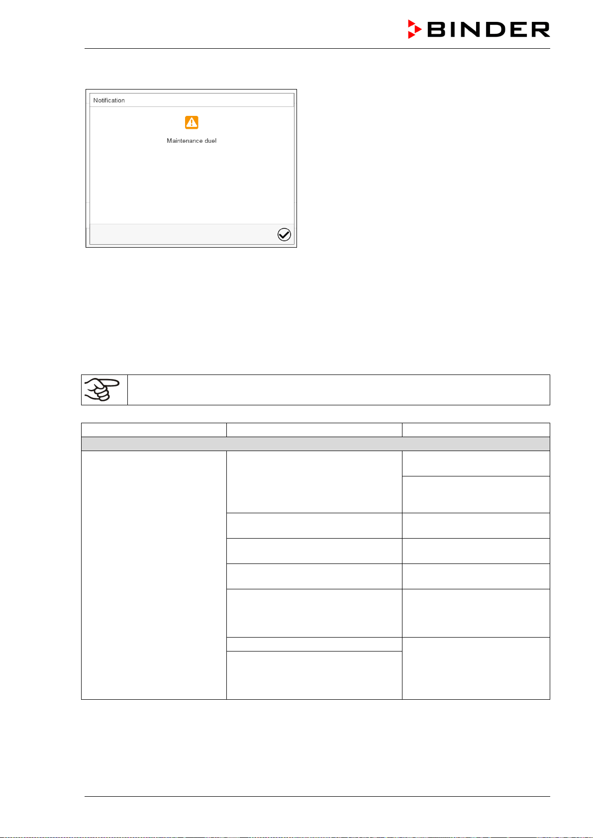
MKF / MKFT (E5) 06/2020 page 135/176
After 8760 operating hours or two years the following message appears:
After confirmation with the Confirm icon, the
message window will pop up again every two
weeks until it is reset by BINDER Service.
23.3 Simple troubleshooting
Defects and shortcomings can compromise the operational safety of the chamber and can lead to risks
and damage to equipment and persons. If there are is a technical fault or shortcoming, take the chamber
out of operation and inform BINDER Service. If you are not sure whether there is a technical fault, pro-
ceed according to the following list. If you cannot clearly identify an error or there is a technical fault,
please contact BINDER Service.
Only qualified service personnel authorized by BINDER must perform repair.
Repaired chambers must comply with the BINDER quality standards.
Fault description
Possible cause
Required measures
General
Chamber without function.
No power supply.
Check connection to power
supply.
Check whether the chamber is
turned on at the main power
switch.
Wrong voltage.
Check power supply for correct
voltage (chap. 4.8).
Main power switch (1) not turned on
Turn on the main power switch
(1).
MKF/MKFT 115, 240, 720: Rear
power switch (12) not turned on.
Turn on the rear power switch
(12).
Chamber fuse has responded.
Check chamber fuse and re-
place it if appropriate. If it re-
sponds again, contact BINDER
service.
Controller defective.
Contact BINDER service.
Nominal temperature exceeded by
20 °C due to chamber failure. Over
temperature protective device (class
1) responds.
MKF / MKFT (E5) 06/2020 page 136/176
Fault description
Possible cause
Required measures
Heating
Chamber heating permanently,
set-point not maintained.
Semiconductor relay defective.
Contact BINDER service.
Pt 100 sensor defective
Controller defective.
Controller not adjusted.
Calibrate and adjust controller.
Chamber doesn’t heat up.
Heating element defective.
Contact BINDER service.
Semiconductor relay defective
Chamber doesn’t heat up when
turned on.
Safety controller responds.
Inner chamber temperature has
reached the safety controller setpoint.
Safety controller set too low.
Acknowledge the alarm on the
controller. Check temperature
setpoint setting. If appropriate,
select suitable safety controller
setpoint (chap. 12.2).
Safety controller (chap. 12.2) defec-
tive.
Contact BINDER service.
Safety controller class 2
responds.
Limit temperature reached.
Acknowledge the alarm on the
controller. Disconnect the
chamber from the power supply
and let it cool down. Detect
cause and remove it.
Start up the chamber and check
control functions. If appropriate,
select suitable limit value.
Over-/under temperature safety
device class 2 (option)
responds.
Limit temperature reached.
Acknowledge the alarm on the
controller. Disconnect the
chamber from the power supply
and let it cool down. Detect
cause and remove it. Press
button “RESET CL 2.0” (2).
Start up the chamber and check
control functions. If appropriate,
select suitable limit value.
Refrigerating performance
No or low refrigerating perfor-
mance.
Ambient temperature > 25 °C / 77°F
(chap.3.4).
Select cooler place of installa-
tion.
Combination of temperature/humidity
values not in the optimum range (see
temperature humidity diagram, Figure
19).
Select combination of tempera-
ture/humidity values in the op-
timum range (chap. 17).
Compressor not turned on.
Contact BINDER service.
Electro-valves defective.
No or not enough refrigerant.
No refrigerating performance;
information message “Preheat
phase” on the controller dis-
play.
MKF 56: Main power switch (1)
turned on less than 1 hour before
operating the chamber.
Turn on the main power switch
(1) at least one hour before
operating the chamber.
MKF / MKFT 115, 240, 720: Main
power switch (1) and/or rear power
switch (12) turned on less than 1 hour
before operating the chamber.
Turn on the main power switch
(1) and/or the rear power switch
(12) at least one hour before
operating the chamber.
Condensation
Condensation at the samples.
Heating-up phase without anti-
condensation protection.
Use the anti-condensation pro-
tection (chap. 19).
Heating up very fast.
Select lower heating up speed
(ramp).
MKF / MKFT (E5) 06/2020 page 137/176
Fault description
Possible cause
Required measures
Condensation (continued)
Condensation or icing at the
sides of the inner chamber.
Set-point for a long time below ambi-
ent temperature, icing in the preheat-
ing chamber.
Defrost the chamber (chap. 18).
Condensation at the samples
or at the sides of the inner
chamber; information message
“Preheat phase” on the control-
ler display.
MKF 56: Main power switch (1)
turned on less than 1 hour before
operating the chamber.
Turn on the main power switch
(1) at least one hour before
operating the chamber.
MKF / MKFT 115, 240, 720: Main
power switch (1) and/or rear power
switch (12) turned on less than 1 hour
before operating the chamber.
Turn on the main power switch
(1) and/or the rear power switch
(12) at least one hour before
operating the chamber.
Humidity
Humidity fluctuation:
Control accuracy of +/- 2.5 %
r.H. is not reached.
Door gasket defective.
Replace door gasket.
Door opened very frequently. Open doors less frequently.
Humidity fluctuation, together
with temperature fluctuation
> 1 °C with a set-point approx.
3 °C above ambient tempera-
ture.
Place of installation too hot.
Select cooler place of installa-
tion or contact BINDER service.
No or low dehumidification.
Capillary tube blocked.
Contact BINDER service.
Not enough refrigerant.
No dehumidification; infor-
mation message “Preheat
phase” on the controller dis-
play.
MKF 56: Main power switch (1)
turned on less than 1 hour before
operating the chamber.
Turn on the main power switch
(1) at least one hour before
operating the chamber.
MKF / MKFT 115, 240, 720: Main
power switch (1) and/or rear power
switch (12) turned on less than 1 hour
before operating the chamber.
Turn on the main power switch
(1) and/or the rear power switch
(12) at least one hour before
operating the chamber.
Icing at the sides of the inner
chamber.
Set-point was too long below ambient
temperature.
Defrost the chamber (chap. 18).
Condensation at the sides of
the inner chamber.
Combination of temperature/humidity
set-point values not in the optimum
range (see temperature humidity
diagram, Figure 19)
Select combination of tempera-
ture/humidity set-point values in
the optimum range (chap. 17).
Temperature set-point was too long
below ambient temperature, icing in
the preheating chamber.
Defrost the chamber (chap. 18)
Combination of temperature/humidity
set-point values leads to falling below
the dew point.
Select suitable combination of
temperature/humidity set-point
values.
Low humidity and temperature
accuracy
MKF 56: Fan speed has been re-
duced.
MKF 56: Set fan speed to
100%.
Controller
No chamber function
(dark display).
Display mode “Standby” active. Press on touchscreen.
Main power switch (1) not turned on
Turn on the main power switch
(1).
MKF/MKFT 115, 240, 720: Rear
power switch (12) not turned on.
Turn on the rear power switch
(12).
Menu functions not available.
Menu functions not available with
current authorization level.
Log in with the required higher
authorization or contact
BINDER service to obtain an
activation code (chap. 13.6).
No access to controller
Password incorrect.
Contact BINDER service.
MKF / MKFT (E5) 06/2020 page 138/176
Fault description
Possible cause
Required measures
Controller (continued)
Chart recorder function: meas-
ured-value memory cleared;
information lost.
New setting of storage rate or scaling
(minimum and/or maximum) (chap.
16.2).
Change the storage rate or
scaling ONLY if the previously
registered data are no longer
required.
Controller does not equilibrate
to setpoints entered in Fixed
value operation mode
Controller is not in Fixed value opera-
tion mode.
Change to Fixed value opera-
tion mode.
Humidity control is turned off.
Turn on humidity control (chap.
6.3).
Controller does not equilibrate
to program set-points.
Controller is not in program operation
mode, or program delay time is run-
ning.
Start the program again. If ap-
propriate, wait for the program
delay time.
Program duration longer than
programmed.
Tolerances have been programmed.
For rapid transition phases, do
NOT program tolerance limits in
order to permit maximum heat-
ing, refrigerating, or humidifica-
tion speed.
Program keeps the last pro-
gram setpoint constant while in
setting “ramp”.
Program line with setting “ramp” is
incomplete.
When programming with setting
“ramp”, define the end value of
the desired cycle by adding an
additional section with a section
time of at least one second.
Ramp temperature transitions
are only realized as steps.
Setting “step” has been selected. Select setting “ramp”.
Humidity alarm when operating
without water connection.
Humidity control turned on.
Turn off humidity control (chap.
6.3).
Acknowledging the alarm does
not cancel the alarm state.
Cause of alarm persists.
Remove cause of alarm. If the
alarm state continues, contact
BINDER service.
Alarm message:
- - - - or <-<-< or >->->
Sensor rupture between sensor and
controller or Pt 100 sensor defective.
Contact BINDER service.
Short-circuit.
Miscellaneous
Impaired valve function of hose
burst protection.
Calcification.
Remove calcifications by citric
acid or acetic acid solutions
(chap. 4.6).
Have a plumber inspect the
valve.
MKF / MKFT (E5) 06/2020 page 139/176
23.4 Sending the chamber back to BINDER GmbH
If you return a BINDER product to us for repair or any other reason, we will only accept the product upon
presentation of an authorization number (RMA number) that has previously been issued to you. An
authorization number will be issued after receiving your complaint either in writing or by telephone prior
to your sending the BINDER product back to us. The authorization number will be issued following receipt
of the information below:
• BINDER product type and serial number
• Date of purchase
• Name and address of the dealer from which you bought the BINDER product
• Exact description of the defect or fault
• Complete address, contact person and availability of that person
• Exact location of the BINDER product in your facility
• A contamination clearance certificate (chap. 28) must be faxed in advance
The authorization number must be applied to the packaging in such a way that it can be easily recognized
or be recorded clearly in the delivery documents.
For security reasons we cannot accept a chamber delivery if it does not carry an authorization
number.
Return address:
BINDER GmbH
Abteilung Service
Gänsäcker 16
78502 Tuttlingen
Germany
24. Disposal
24.1 Disposal of the transport packing
Packing element
Material
Disposal
Straps to fix packing on pallet
(sizes 56, 115, 240)
Plastic Plastic recycling
Wooden transport box (size 720;
option for sizes 56, 115, 240)
with metal screws
Non-wood (compressed
matchwood, IPPC standard)
Wood recycling
Metal
Metal recycling
Pallet
with foamed plastic stuffing
Solid wood (IPPC standard)
Wood recycling
PE foam
Plastic recycling
Shipping box (sizes 56, 115, 240)
with metal clamps
Cardboard
Paper recycling
Metal
Metal recycling
Top cover
Cardboard
Paper recycling
Edge protection
Styropor
®
or PE foam
Plastic recycling
Protection of doors and racks
PE foam
Plastic recycling
Upholstered transport piece
(L-type profile) for door support
Steel or aluminum with plastic
Keep it for transportation purpose.
Disposal: Metal recycling
Bag for operating manual
PE foil
Plastic recycling
Insulating air cushion foil (packing
of optional accessories)
PE foil Plastic recycling
If recycling is not possible, all packing parts can also be disposed of with normal waste.
MKF / MKFT (E5) 06/2020 page 140/176
24.2 Decommissioning
• Turn off the chamber at the main power switch On/Off (1) and disconnect it from the power supply.
• MKF/MKFT 115, 240, 720: Turn off the rear power switch (12).
• Close the tap used for the water supply.
• Turn off humidity control (chap. 6.3).
• Remove the water installation.
• Temporal decommissioning: See indications for appropriate storage, chap. 3.3.
In case of a prolonged temporal decommissioning: Leave the chamber door open or remove the ac-
cess port plugs. For several weeks out of service, we recommend turning on the chamber every 3
days and operating it about 30 minutes in the cooling mode. This will ensure a quicker restart.
• Final decommissioning: Dispose of the chamber as described in chap. 24.3 to 24.5.
24.3 Disposal of the chamber in the Federal Republic of Germany
According to Annex I of Directive 2012/19/EU of the European Parliament and of the Council on waste
electrical and electronic equipment (WEEE), BINDER devices are classified as “monitoring and control
instruments” (category 9) only intended for professional use“. They must not be disposed of at public col-
lecting points.
The chambers bear the symbol for the marking of electrical and electronic equipment man-
ufactured / placed on the market in the EU after 13 August 2005 and be disposed of in sep-
arate collection according to Directive 2012/19/EU on waste el
ectrical and electronic
equipment (WEEE) and German national law for electrical and electronic equipment (El-
ektro- und Elektronikgerätegesetz, ElektroG). WEEE marking: crossed-out wheeled bin with
solid bar under. A significant part of the materials must be recycled in order to protect the
environment.
At the end of the device’s service life, have the chamber disposed of according to the German national
law for electrical and electronic equipment (Elektro- und Elektronikgerätegesetz, ElektroG from 20 Octo-
ber 2015, BGBl. I p. 1739) or contact BINDER service who will organize taking back and disposal of the
chamber according to the German national law for electrical and electronic equipment (Elektro- und El-
ektronikgerätegesetz, ElektroG from 20 October 2015, BGBl. I p. 1739).
NOTICE
Danger of violation against existing law if not disposed of properly.
∅ Do NOT dispose of BINDER devices at public collecting points.
Have the device disposed of professionally at a recycling company which is certified
according to the German national law for electrical and electronic equipment (Elektro-
und Elektronikgerätegesetz, ElektroG from 20 October 2015, BGBl. I p. 1739).
or
Instruct BINDER Service to dispose of the device. The general terms of payment and
delivery of BINDER GmbH apply, which were valid at the time of purchasing the cham-
ber.
Certified companies disassemble waste (used) BINDER equipment in primary substances for recycling
according to Directive 2012/19/EU. The devices must be free from toxic, infectious or radioactive sub-
stances in order to eliminate any health hazards to the employees of the recycling companies.
MKF / MKFT (E5) 06/2020 page 141/176
Prior to handing the chamber over to a recycling company, it is the user’s responsibility that it
is free from toxic, infectious or radioactive substances.
• Prior to disposal, clean all introduced or residual toxic substances from the chamber.
• Prior to disposal, disinfect the chamber
from all sources of infection. Be aware that sources
of infection may also be located outside the inner chamber.
• If you cannot safely remove all toxic substances and sources of infection from the cham-
ber, dispose of it as “special” waste according to national law.
• Fill out the contamination clearance certificate (chap. 28) and enclose it with the chamber.
WARNING
Danger of intoxication and infection through contamination of the chamber with
toxic, infectious or radioactive substances.
Damages to health.
∅ NEVER take a chamber contaminated with toxic substances or sources of infection for
recycling according to Directive 2012/19/EU.
Prior to disposal, remove all toxic substances and sources of infection from the cham-
ber.
A chamber from which all toxic substances or sources of infection cannot be safely
removed must be considered as “special” waste according to national law. Dispose of it
accordingly.
The refrigerants used 452a and R 23 (only MKFT) are not inflammable at ambient pressure. They must
not escape into the environment. In Europe, recovery of the refrigerants R452a (GWP 2140) and R 23
(GWP 12100) is mandatory according to regulation No. 842/2006/EC. Ensure the compliance with the
applicable legal requirements regarding qualification of staff, disposal, and documentation.
24.4 Disposal of the chamber in the member states of the EU except for the Fed-
eral Republic of Germany
According to Annex I of Directive 2012/19/EU of the European Parliament and of the Council on waste
electrical and electronic equipment (WEEE), BINDER devices are classified as “monitoring and control
instruments” (category 9) only intended for professional use“. They must not be disposed of at public col-
lecting points.
The chambers bear the symbol for the marking of electrical and electronic equipment man-
ufactured / placed on the market in the EU after 13 August 2005 and be disposed of in
separate collection according to the Directive 2012/19/EU on waste electrical and electron-
ic equipment (WEEE). WEEE marking: crossed-out wheeled bin with solid bar under.
At the end of the device’s service life, notify the distributor who sold you the device, who
will take back and dispose of the chamber according to the Directive 2012/19/EU on waste
electrical and electronic equipment (WEEE).
MKF / MKFT (E5) 06/2020 page 142/176
NOTICE
Danger of violation against existing law if not disposed of properly.
∅ Do NOT dispose of BINDER devices at public collecting points.
Have the device disposed of professionally at a recycling company that is certified ac-
cording to conversion of the Directive 2012/19/EU into national law.
or
Instruct the distributor who sold you the device to dispose of it. The agreements apply
that were agreed with the distributor when purchasing the chamber (e.g. his general
terms of payment and delivery).
If your distributor is not able to take back and dispose of the chamber, please contact
BINDER service.
Certified companies disassemble waste (used) BINDER equipment in primary substances for recycling
according to Directive 2012/19/EU. The devices must be free from toxic, infectious or radioactive sub-
stances in order to eliminate any health hazards to the employees of the recycling companies.
Prior to handing the chamber over to a recycling company, it is the user’s responsibility that it
is free from toxic, infectious or radioactive substances.
• Prior to disposal, clean all introduced or residual toxic substances from the chamber.
• Prior to disposal, disinfect the chamber
from all sources of infection. Be aware that sources
of infection may also be located outside the inner chamber.
• If you cannot safely remove all sources of infection and toxic substances from the cham-
ber, dispose of it as “special” waste according to national law.
• Fill out the contamination clearance certificate (chap. 28) and enclose it with the chamber.
WARNING
Danger of intoxication and infection through contamination of the chamber with
toxic, infectious or radioactive substances.
Damages to health.
∅ NEVER take a chamber contaminated with toxic substances or sources of infection for
recycling according to Directive 2012/19/EU.
Prior to disposal, remove all toxic substances and sources of infection from the cham-
ber.
A chamber from which all toxic substances or sources of infection cannot be safely
removed must be considered as “special” waste according to national law. Dispose of it
accordingly.
The refrigerants used 452a and R 23 (only MKFT) are not inflammable at ambient pressure. They must
not escape into the environment. In Europe, recovery of the refrigerants R452a (GWP 2140) and R 23
(GWP 12100) is mandatory according to regulation No. 842/2006/EC. Ensure the compliance with the
applicable legal requirements regarding qualification of staff, disposal, and documentation.
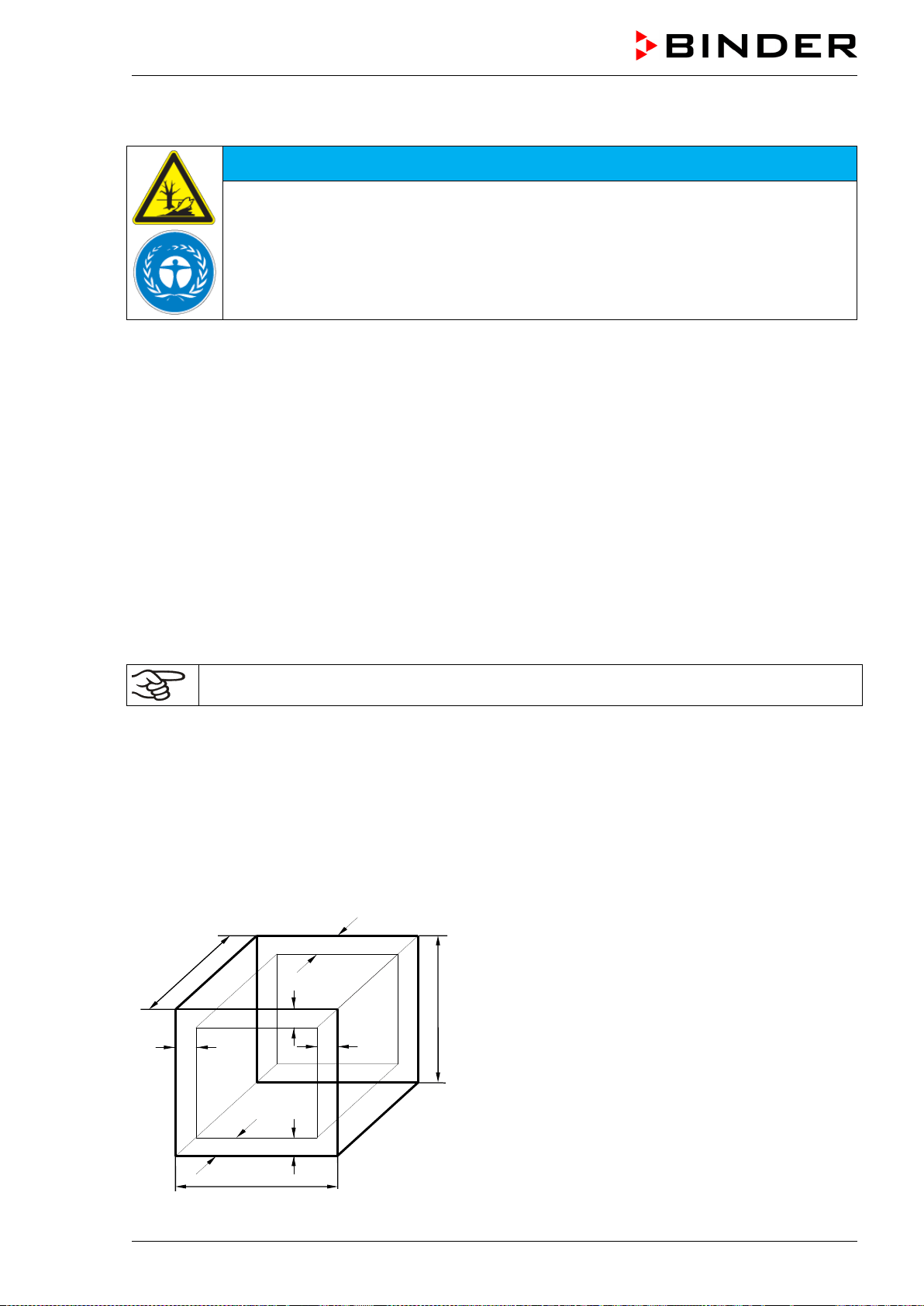
MKF / MKFT (E5) 06/2020 page 143/176
24.5 Disposal of the chamber in non-member states of the EU
NOTICE
Danger of violation against existing law if not disposed of properly.
Alteration of the environment.
For final decommissioning and disposal of the chamber, please contact BINDER ser-
vice.
Follow the statutory regulations for appropriate, environmentally friendly disposal.
The main board of the chamber includes a lithium cell. Please dispose of it according to national regula-
tions.
The refrigerants used 452a and R 23 (only MKFT) are not inflammable at ambient pressure. They must
not escape into the environment. In Europe, recovery of the refrigerants R452a (GWP 2140) and R 23
(GWP 12100) is mandatory according to regulation No. 842/2006/EC. Ensure the compliance with the
applicable legal requirements regarding qualification of staff, disposal, and documentation.
25. Technical description
25.1 Factory calibration and adjustment
The chambers were calibrated and adjusted in the factory. Calibration and adjustment were performed
using standardized test instructions, according to the QM DIN EN ISO 9001 system applied by BINDER
(certified since December 1996 by TÜV CERT). All test equipment used is subject to the administration of
measurement and test equipment that is also constituent part of the BINDER QM DIN EN ISO
9001systems. They are controlled and calibrated to a DKD-Standard at regular intervals.
Repeated calibrations are recommended in periods of 12 months.
25.2 Over current protection
The chambers are equipped with an internal protection not accessible from outside. If these fuses have
responded, please contact an electronic engineer or BINDER service.
25.3 Definition of usable volume
The usable volume illustrated below is calculated as follows:
c
c
b
a
C
B
A
b
a
A, B, C = internal dimensions (W, H, D)
a, b, c = distance to wall
a = 0.1*A
b = 0.1*B
c = 0.1*C
V
USE
= (A - 2 * a) * (B - 2 * b) * (C - 2 * c)
Figure 28: Determination of the useable volume
MKF / MKFT (E5) 06/2020 page 144/176
The technical data refers to the defined usable volume.
Do NOT place samples outside this usable volume.
Do NOT load this volume by more than half to enable sufficient airflow inside the chamber.
Do NOT divide the usable volume into separate parts with large area samples.
Do NOT place samples too close to each other in order to permit circulation between them
and thus obtain a homogenous distribution of temperature and humidity.
25.4 MKF (E5) technical data
Chamber size
56
115
240
720
Exterior dimensions
Width, gross (including 18 mm / 0.7 in for
1 access port (MKF 56, 115, 240), 36 mm
/ 1.4 in for 2 access ports (MKF 720) with
plug)
mm
inch
745
29.33
1000
39.37
1135
44.69
1615
63.58
Height, gross (incl. castors)
mm
inch
1450
57.09
1725
67.91
1715
67.52
2005
78.94
Depth, gross (incl. cable and door handle)
mm
inch
835
32.87
915
36.02
1000
39.37
1230
48.43
Depth, gross (incl. cable and door handle)
with optional compressed air dryer
mm
inch
985
38.78
1085
42.72
1170
46.06
1400
55.12
Depth, gross (incl. cable and door handle)
with voltage and frequency changer
mm
inch
--
1530
60.24
1615
63.58
1845
72.64
Wall clearance rear (minimum)
mm / inch
300 / 11.81
300 / 11.81
300 / 11.81
300 / 11.81
Wall clearance rear with optional com-
pressed air dryer or to set up the voltage
and frequency changer (minimum)
mm
inch
1000
39.37
1000
39.37
1000
39.37
1000
39.37
Wall clearance sides (minimum)
mm / inch
200 / 7.87
200 / 7.87
200 / 7.87
200 / 7.87
Window width
mm / inch
288 / 11.34
288 / 11.34
508 / 19.99
508 / 19.99
Window height
mm / inch
255 / 10.04
222 / 8.74
300 / 11.81
300 / 11.81
Doors
Number of doors
1
1
1
1
Interior dimensions
Width
mm
inch
400
15.75
600
23.62
735
28.94
1200
47.24
Height
mm / inch
420 / 16.54
480 / 18.90
700 / 27.56
1020 / 40.16
Depth
mm / inch
318 / 12.52
400 / 15.75
443 / 17.44
600 / 23.62
Interior volume
l / cu.ft.
60 / 2.12
115 / 4.06
228 / 8.05
734 / 25.92
Racks
Quantity of racks (regular)
1
1
1
1
Quantity of racks (max.)
4
4
6
11
Maximum load per rack
kg / lbs.
15 / 33
30 / 66
30 / 66
40 / 88
Maximum permitted total load
kg / lbs.
60 / 132
60 / 132
70 / 155
160 / 353
Weight
Weight (empty)
kg / lbs.
175 / 386
280 / 617
360 / 794
590 / 1300
Weight (empty) with optional compressed
air dryer
kg / lbs. 200 295 / 650 375 / 827 605 / 1334
MKF / MKFT (E5) 06/2020 page 145/176
Chamber size
56
115
240
720
Temperature data (without humidity)
Temperature range
°C
°F
-40 to +180
-40 to 356
-40 to +180
-40 to 356
-40 to +180
-40 to 356
-40 to +180
-40 to 356
Temperature fluctuation
+/- K
0.1 to 0.5
0.1 to 0.6
0.1 to 0.5
0.1 to 0.5
Temperature uniformity (variation)
+/- K
0.5 to 1.5
0.1 to 1.3
0.1 to 1.5
0.1 to 1.8
Average heating up speed
acc. to IEC 60068-3-5
K/min. 5.0 5.5 5.0 4.8
Average cooling down speed
acc. to IEC 60068-3-5
K/min. 5.0 4.5 5.0 4.8
Heating up from -40 °C to 180 °C
minutes
60
60
60
85
Cooling down time from 180 °C to -40 °C
minutes
90
100
120
120
Max. heat compensation at 25 °C / 77 °F
W
1200
2100
2800
5800
Climatic data (with humidity)
Temperature range
°C
°F
+10 to +95
50 to 203
+10 to +95
50 to 203
+10 to +95
50 to 203
+10 to +95
50 to 203
Temperature range with optional com-
pressed air dryer
°C
°F
0 to +95
32 to 203
0 to +95
32 to 203
0 to +95
32 to 203
0 to +95
32 to 203
Temperature fluctuation
+/- K
0.1 to 1.3
0.1 to 1.3
0.1 to 1.3
0.2 to 1.5
Temperature uniformity (variation)
+/- K
0.5 to 1.5
--
--
--
Humidity range
% r.h.
10 to 98
10 to 98
10 to 98
10 to 98
Humidity range with optional compressed
air dryer
% r.h. 5 to 98 5 to 98 5 to 98 5 to 98
Humidity fluctuation
+/- % r.h.
≤ 2.5
≤ 2.5
≤ 2.5
≤ 2.5
Dew point temperature range
°C
°F
+5 to +94
41 to 201
+5 to +94
41 to 201
+5 to +94
41 to 201
+5 to +94
41 to 201
Dew point temperature range with optional
compressed air dryer
°C
°F
-28 to +94
-18.4 to 201
-28 to +94
-18.4 to 201
-28 to +94
-18.4 to 201
-28 to +94
-18.4 to 201
Max. heat compensation at 25 °C / 77 °F
and 90 % r.h.
(without optional compressed air dryer)
W 400 400 400 1000
Electrical data
System of protection acc. to EN 60529
IP
20
20
20
20
Nominal voltage (+/-10%) at 50 Hz power
frequency
V 230 400 400 400
Current type
1N~
3N~
3N~
3N~
Nominal power
kW
2.80
4.80
6.80
11.00
Power plug
IEC con-
nector plug
(grounded)
CEE plug
5-poles
16 A
CEE plug
5-poles
16 A
CEE plug
5-poles
32 A
Over-voltage category acc. to IEC 61010-1
II
II
II
II
Pollution degree acc. to IEC 61010-1
2
2
2
2
Over-current release category B, internal
Amp
16
3 x 16
3 x 16
3 x 25
Different electrical data for chambers constructed for the USA and Canada
(model version MKF056-240V)
Nominal voltage (+/-10%) at 60 Hz power
frequency
V 240 -- -- --
Current type
2~
--
--
--
MKF / MKFT (E5) 06/2020 page 146/176
Chamber size
56
115
240
720
Electrical data of the voltage and frequency changer
System of protection acc. to EN 60529
IP
--
23
23
23
Nominal voltage (+/-10%) at 60 Hz power
frequency (input side)
V -- 480 480 480
Current type
--
3N~
3N~
3N~
Nominal power
kW
--
9
9
13
Over-voltage category acc. to IEC 61010-1
--
II
II
II
Pollution degree acc. to IEC 61010-1
--
2
2
2
Fuse
A
--
16
16
25
Environment-specific data
Noise level (mean value)
dB(A)
59
62
65
65
Noise level with optional compressed air
dryer (short-term) (mean value)
dB(A) 85 85 85 85
Noise level with voltage and frequency
changer (mean value)
dB(A) -- 67 67 67
Energy consumption at +25 °C
/ 77 °F
and
60 % r.h.
Wh/h 800 1000 1500 3000
Filling weight of refrigerant R 452A (GWP
2140)
kg / lbs. 1.50 / 33.1 2.00 / 4.41 2.20 / 4.85 5.00 / 11.02
Note: Chambers with voltage and frequency changer: Average heating up time reduced by 0.3 K/min
each.
All technical data is specified for unloaded chambers with standard equipment at an ambient temperature
of +22 °C +/- 3 °C / 71.6 °F +/- 5.4 °F and a power supply voltage fluctuation of +/-10%. Technical data is
determined in accordance to BINDER Factory Standard Part 2:2015 and DIN 12880:2007.
All indications are average values, typical for chambers produced in series. We reserve the right
to change technical specifications at any time.
If the chamber is fully loaded, the specified heating up and cooling down times may vary ac-
cording to the load.
Bringing a source of humidity into the inner chamber will affect the minimum humidity specifi-
cation and may affect the humidity accuracy.
25.5 MKFT (E5) technical data
Chamber size
115
240
720
Exterior dimensions
Width, gross (including 18 mm /
0.7 in
for 1 access
port (MKFT 115, 240), 36 mm / 1.4 in for 2 access
ports (MKFT 720), with plug)
mm / inch 1000 / 39.37
1135 / 44.69
1615 / 63.58
Height, gross (incl. castors)
mm / inch
1725 / 67.91
1940 / 76.38
2005 / 78.94
Depth, gross (incl. cable and door handle)
mm / inch
915 / 36.02
1000/ 39.37
1230 / 48.43
Depth, gross (incl. cable and door handle) with op-
tional compressed air dryer
mm / inch 1085 / 42.72
1170 / 46.06
1400 / 55.12
Depth, gross (incl. cable and door handle) with volt-
age and frequency changer
mm / inch 1530 / 60.24
1615 / 63.58
1845 / 72.64
MKF / MKFT (E5) 06/2020 page 147/176
Chamber size
115
240
720
Exterior dimensions
Wall clearance rear (minimum)
mm / inch
300 / 11.81
300 / 11.81
300 / 11.81
Wall clearance rear with optional compressed air
dryer or to set up the voltage and frequency chang-
er (minimum)
mm / inch 1000 / 39.37
1000 / 39.37
1000 / 39.37
Wall clearance sides (minimum)
mm / inch
200 / 7.87
200 / 7.87
200 / 7.87
Window width
mm / inch
288 / 11.34
508 / 19.99
508 / 19.99
Window height
mm / inch
222 / 8.74
300 / 11.81
300 / 11.81
Doors
Number of doors
1
1
1
Interior dimensions
Width
mm / inch
600 / 23.62
735 / 28.94
1200 / 47.24
Height
mm / inch
480 / 18.90
700 / 27.56
1020 / 40.16
Depth
mm / inch
400 / 15.75
443 / 17.44
600 / 23.62
Interior volume
l / cu.ft.
115 / 4.06
228 / 8.05
734 / 25.92
Racks
Quantity of racks (regular)
1
1
1
Quantity of racks (max.)
4
6
11
Maximum load per rack
kg / lbs.
30 / 66
30 / 66
40 / 88
Maximum permitted total load
kg / lbs.
60 / 132
70 / 155
160 / 353
Weight
Weight (empty)
kg / lbs.
330 / 728
415 / 915
635 / 1400
Weight (empty)
with optional compressed air dryer
kg / lbs. 345 / 761 430 / 948 650 / 1433
Temperature data (without humidity)
Temperature range
°C
°F
-70 to +180
-94 to 356
-70 to +180
-94 to 356
-70 to +180
-94 to 356
Temperature fluctuation
± K
0.1 to 0.5
0.1 to 0.5
0.1 to 0.5
Temperature uniformity (variation)
± K
0.1 to 1.3
0.2 to 1.8
0.3 to 2.0
Average heating up speed acc. to IEC 60068-3-5
K/min.
5.5
5.0
4.8
Average cooling down speed acc. to IEC 60068-3-5
K/min.
4.2
4.2
4.0
Heating up time from -70 °C to 180 °C
minutes
60
75
80
Cooling down time from 180 °C to -70 °C
minutes
110
110
120
Max. heat compensation at 25 °C / 77°F
W
1500
3000
5000
Climatic data (with humidity)
Temperature range
°C
°F
+10 to +95
50 to 203
+10 to +95
50 to 203
+10 to +95
50 to 203
Temperature range
with optional compressed air dryer
°C
°F
0 to +95
32 to 203
0 to +95
32 to 203
0 to +95
32 to 203
Temperature fluctuation
± K
0.1 to 1.0
0.1 to 1.5
0.1 to 1.0
Humidity range
% r.h.
10 to 98
10 to 98
10 to 98
Humidity range with optional compressed air dryer
% r.h.
5 to 98
5 to 98
5 to 98
Humidity fluctuation
± % r.h.
≤ 2.5
≤ 2.5
≤ 2.5
Dew point temperature range
°C
°F
+5 to +94
41 to 201
+5 to +94
41 to 201
+5 to +94
41 to 201
Dew point temperature range
with optional compressed air dryer
°C
°F
-28 to +94
-18.4 to 201
-28 to +94
-18.4 to 201
-28 to +94
-18.4 to 201
Max. heat compensation at 25 °C / 77 °F and 90 %
r.h. (without optional compressed air dryer)
W 400 400 800
MKF / MKFT (E5) 06/2020 page 148/176
Chamber size
115
240
720
Electrical data
IP-system of protection acc. to EN 60529
IP
20
20
20
Nominal voltage (+/-10%) at 50 Hz power frequency
V
400
400
400
Current type
3N~
3N~
3N~
Power frequency
Hz
50
50
50
Nominal Power
kW
6.20
7.50
13.00
Power plug
CEE plug
5-poles
16 A
CEE plug
5-poles
16 A
CEE plug
5-poles
32 A
Over-voltage category acc. to IEC 61010-1
II
II
II
Pollution degree acc. to IEC 61010-1
2
2
2
Over-current release category B, 3 x internal
Amp
16
16
25
Electrical data of the voltage and frequency changer
IP-system of protection acc. to EN 60529
IP
23
23
23
Nominal voltage (+/-10%) at 60 Hz power frequency
(input side)
V 480 480 480
Current type
3N~
3N~
3N~
Nominal power
kW
9
9
13
Over-voltage category acc. to IEC 61010-1
II
II
II
Pollution degree acc. to IEC 61010-1
2
2
2
Fuse
A
16
16
25
Environment-specific data
Noise level (mean value)
dB(A)
62
65
69
Noise level with optional compressed air dryer
(short-term) (mean value)
dB(A) 85 85 85
Noise level with voltage and frequency changer
(mean value)
dB(A) 67 67 67
Energy consumption at +25 °C / 77 °F and
60 % r.h.
Wh/h 1000 1400 2200
Filling weight of refrigerant R 452A
(1
st
stage cooling, GWP 2140)
kg / lbs. 1.60 / 3.53 2.20 / 4.85 4.00 / 8.82
Filling weight of refrigerant R23
(2
nd
stage cooling, GWP 12100)
kg / lbs. 0.32 / 0.71 0.40 / 0.88 0.87 / 1.92
Note: Chambers with voltage and frequency changer: Average heating up time reduced by 0.3 K/min
each.
All technical data is specified for unloaded chambers with standard equipment at an ambient temperature
of +22 °C +/- °C / 71.6 °F +/- 5.4 °F and a power supply voltage fluctuation of +/-10%. Technical data is
determined in accordance to BINDER Factory Standard Part 2:2015 and DIN 12880:2007.
All indications are average values, typical for chambers produced in series. We reserve the right
to change technical specifications at any time.
If the chamber is fully loaded, the specified heating up and cooling down times may vary ac-
cording to the load.
Bringing a source of humidity into the inner chamber will affect the minimum humidity specifi-
cation and may affect the humidity accuracy.
MKF / MKFT (E5) 06/2020 page 149/176
25.6 Equipment and options (extract)
To operate the chamber, use only original BINDER accessories or accessories / components
from third-party suppliers authorized by BINDER. The user is responsible for any risk arising
from using unauthorized accessories.
Regular equipment
Microprocessor display program controller for temperature and humidity regulation
Electronically controlled humidifying and dehumidifying system with capacitive humidity sensor *)
(humidity range, see diagram)
MKF/MKFT 115, 240, 720: Integrated freshwater can
MKF/MKFT 115, 240, 720: Alarm message in case of lack of water inside the freshwater can
Heated window and interior lighting
Programmable anti-condensation protection of charging material
Environmentally friendly refrigerants R452a (MKF / MKFT) and R 23 (MKFT)
Safety controller (temperature safety device class 2 acc. to DIN 12880:2007)
MKF/MKFT 115, 240, 720: socket 230 V AC, 1N ~ 50-60 Hz, max. load 500W, protection type IP 54
2 zero-voltage relay outputs, addressable via operation lines
Ethernet interface for computer communication
1 access port with silicone plug, diameter 50 mm / 1.97 in left (MKF / MKFT 56, 115, 240),
2 access ports with silicone plug, diameter 80 mm / 3.18 in left and right (MKF / MKFT 720)
Rack, stainless steel
Aeration / venting
Four castors (2 lockable)
*) A water supply (1 to 10 bar) is necessary for the installation of the humidifying and de-humidifying
system. If no suitable house water connection is available, you can manually supply water by filling a
freshwater can (internal water can: regular with MKF/MKFT 115, 240, 720; external water can: option
for MKF 56). Furthermore, a water drain in a max. distance of 3 meters / 9.8 ft. and a max. height of 1
meter / 3.3 ft. is required.
Options / accessories
Additional rack, stainless steel
Perforated rack, stainless steel
Reinforced rack with 1 set of rack lockings
Securing elements for additional fastening of racks (4 pieces)
Lockable door
Communication interface RS485
2 zero-voltage relay outputs, addressable via operation lines
BINDER Data Logger kit for temperature T 220 (chamber values), for temperature / humidity TH 100
(chamber values) or TH 100/70 (chamber and ambient values)
Safety kit for water connection with hose burst protection device and reflux protection device, pre-
mounted assembly (available via BINDER INDIVIDUAL customized solutions)
Access ports 30 mm, 50 mm, 80 mm, 100 mm, 125 mm, left or right, with silicone plug
Over-/under temperature safety device class 2
Analogue outputs 4-20 mA actual and set-point values for temperature and humidity with 6 pole DIN
socket, DIN plug included
Object temperature display with flexible Pt100 temperature sensor
Controlled compressed air dryer suitable for compliance with the common automotive standards
Water cooling
Notch-type access port 35 x 100 mm in the door
MKF / MKFT (E5) 06/2020 page 150/176
Options / accessories
MKF 56: External freshwater and wastewater cans (20 liters / 0.71 cu.ft. each)
BINDER Pure Aqua Service
Exchange cartridge for BINDER Pure Aqua Service
MKF/MKFT 115, 240, 720: Water circle: condensate recycling
Calibration of temperature and humidity including certificate
Spatial temperature and humidity measurement including certificate
Spatial temperature measurement acc. to DIN 12880 and humidity measurement with 9 measuring points
at 25 °C / 77°F and 60% r.h. or at specified values, with measuring protocol and certificate
Qualification folder
If the refrigerating machine is continuously operated, the lifetime of the condenser-fan is 2.3
years.
25.7 Accessories and spare parts (extract)
BINDER GmbH is responsible for the safety features of the chamber only, provided skilled
electricians or qualified personnel authorized by BINDER perform all maintenance and repair,
and if components relating to chamber safety are replaced in the event of failure with original
spare parts. The user is responsible for any risks arising from using unauthorized accessories
/ components.
Chamber size
56
115
240
720
Description
Art. no.
Rack, stainless steel
6004-0150
6004-0008
6004-0097
6004-0102
Perforated rack, stainless steel
6004-0182
6004-0030
8009-0447
8009-0511
Reinforced rack, stainless steel, with 1 set of
rack lockings
8012-1091 8012-0709 8012-0605 8012-0684
Rack lockings (4 pieces)
8012-1092
8012-0620
8012-0620
8012-0620
Door gasket, silicone, inside
6005-0262
6005-0151
6005-0188
6005-0199
Door gasket, silicone, outside
6005-0263
6005-0152
6005-0157
6005-0173
Description
Art. no.
Plug for silicon access port d50
6016-0032
Plug for silicon access port d80
6016-0029
Water connection kit
8009-0135
Safety kit for water connection with hose burst protection device and reflux
protection device
BINDER Individual Cus-
tomized solutions
Data Logger Kit T 220
8012-0715
Data Logger Kit TH 100
8012-0718
Data Logger Kit TH 100/70
8012-0719
BINDER Pure Aqua Service
8012-0759
Exchange cartridge for BINDER Pure Aqua Service
6011-0165
Neutral cleaning agent, 1 kg
1002-0016
For information on components not listed here, please contact BINDER Service.
MKF / MKFT (E5) 06/2020 page 151/176
Validation service
Art. no.
Qualification folder IQ-OQ (printed version)
7007-0002
Qualification folder IQ-OQ (digital version)
7057-0002
Qualification folder IQ-OQ-PQ (printed version)
7007-0006
Qualification folder IQ-OQ-PQ (digital version)
7057-0006
Execution of IQ-OQ
DL420300
Execution of IQ-OQ-PQ
DL440500
Calibration service
Art. no.
Calibration of temperature and humidity including certificate
(1 measuring point)
DL300301
Spatial temperature and humidity measurement including certificate
(9 measuring points temperature, 1 measuring point humidity)
DL300309
Spatial temperature and humidity measurement including certificate
(18 measuring points temperature, 1 measuring point humidity)
DL300318
Spatial temperature and humidity measurement including certificate
(27 measuring points temperature, 1 measuring point humidity)
DL300327
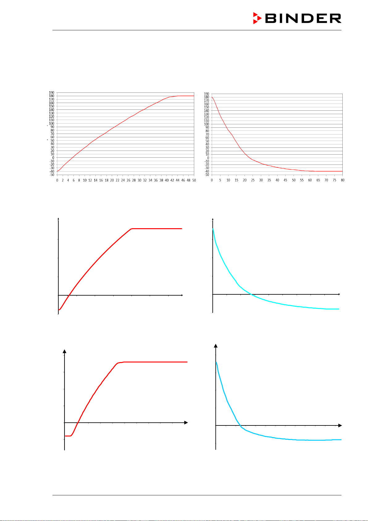
MKF / MKFT (E5) 06/2020 page 152/176
25.8 MKF heating-up and cooling-down graphs
Heating-up graph MKF 56
Temp/°C
t/min
Cooling-down graph MKF56
Temp/°C
t/min
Heating-up graph MKF 115
Cooling-down graph MKF 115
Heating-up graph MKF 240
Cooling-down graph MKF 240
-50
0
50
100
150
200
5
10
20
30
40
50
60
t / min
Temp/°C
-50
0
50
100
150
200
10
20
30
40
50
60
70
80
t/min
Temp/°C
-50
0
50
100
150
200
10
20
30
40
50
60
70
80
90
100
t / min.
Temp. / °C
-50
0
50
100
150
200
10
20
30
40
50
60
70
80
90
100
110
120
t / min.
Temp. / °C
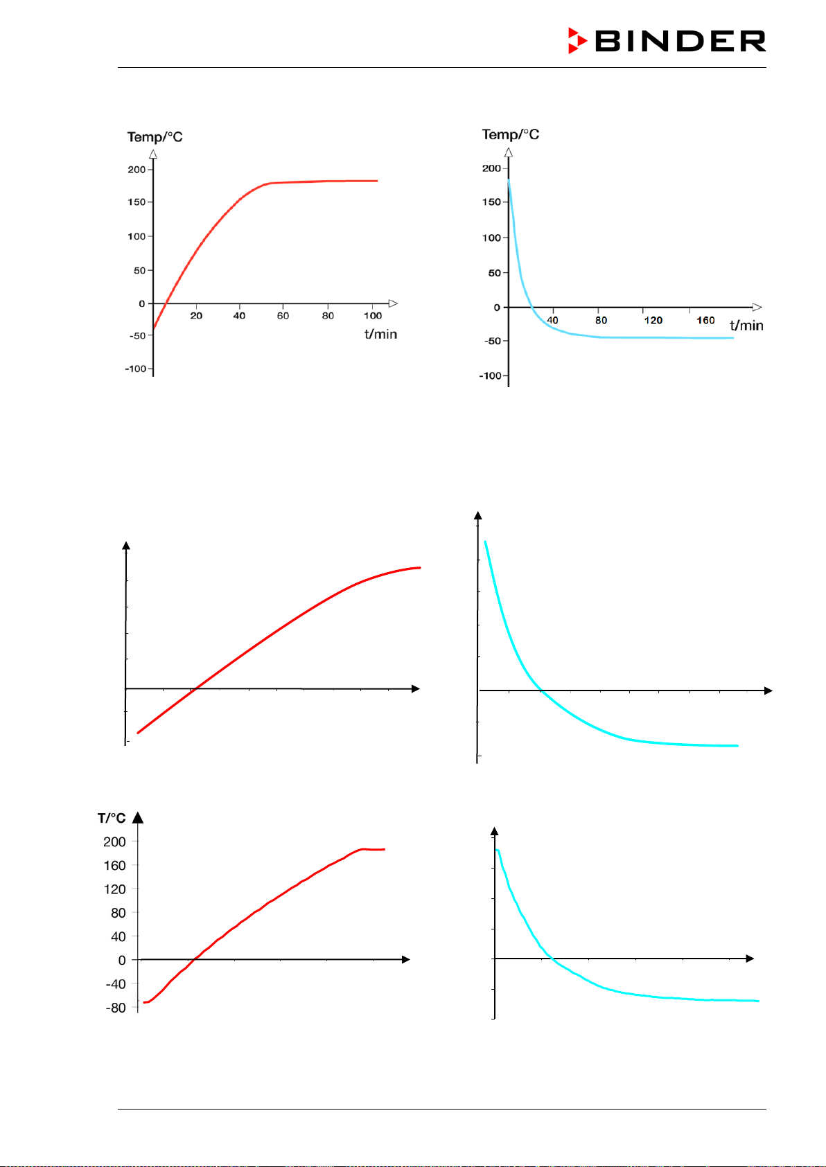
MKF / MKFT (E5) 06/2020 page 153/176
Heating-up graph MKF 720
Cooling-down graph MKF 720
25.9 MKFT heating-up and cooling-down graphs
Heating-up graph MKFT 115
Cooling-down graph MKFT 115
Heating-up graph MKFT 240
Cooling-down graph MKFT 240
0
40
120
160
200
80
-40
-80
t/min
10
15
20
25
30
35
45
50
40
Temp./ °C
20
40
60
80
90
t/min
Temp. / °C
0
40
120
160
200
80
-40
-80
30
50
70
100
t/min
10
20
30
40
50
t/min
Temp. / °C
-100
-50
0
50
100
150
200
20
40
60
80
100
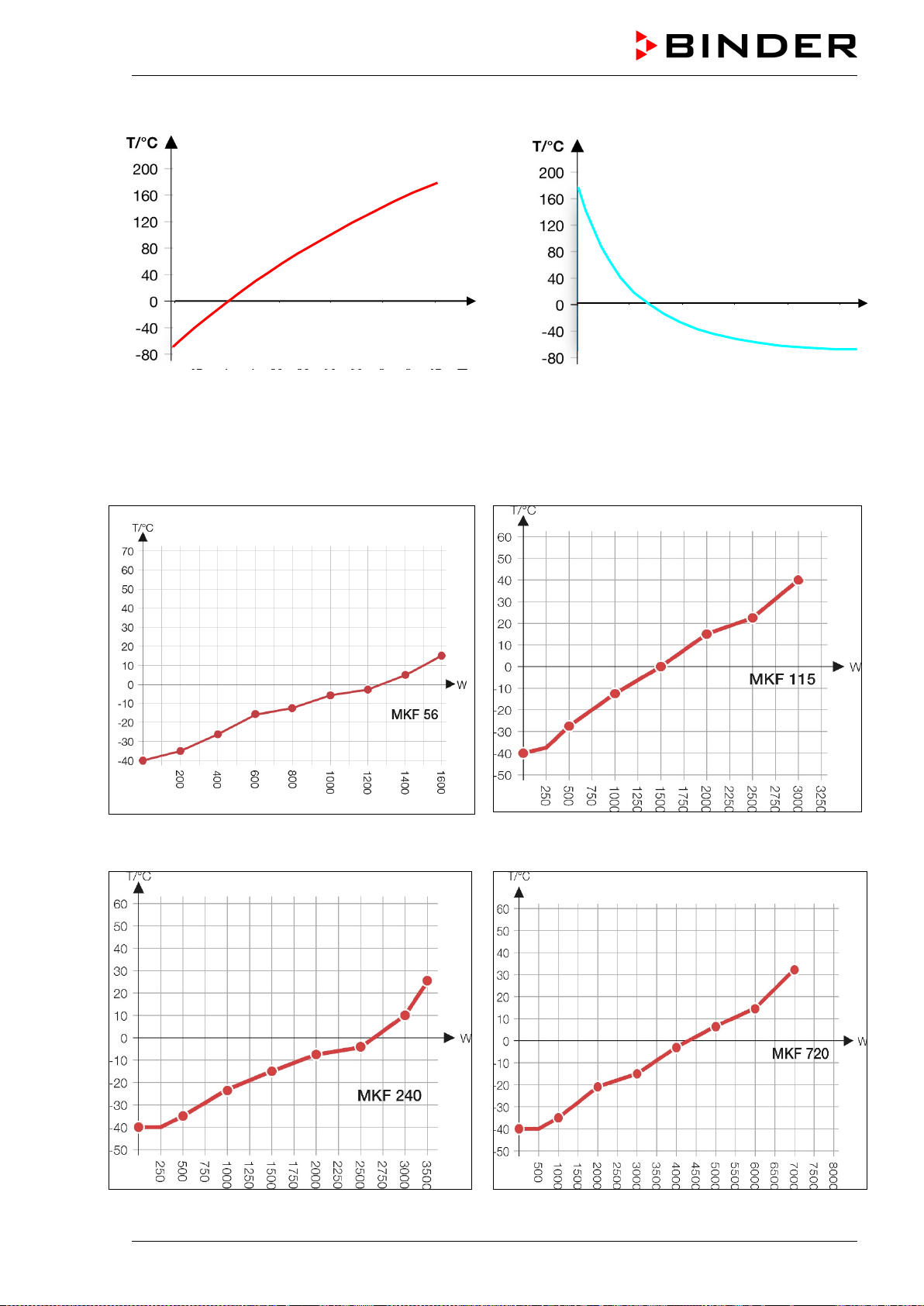
MKF / MKFT (E5) 06/2020 page 154/176
Heating-up graph MKFT 720
Cooling-down graph MKFT 720
25.10 MKF heat compensation graphs
MKF 56 heat compensation
MKF 115 heat compensation
MKF 240 heat compensation
MKF 720 heat compensation
t/min
10
20
30
40
50
20
40
60
80
100
t/min
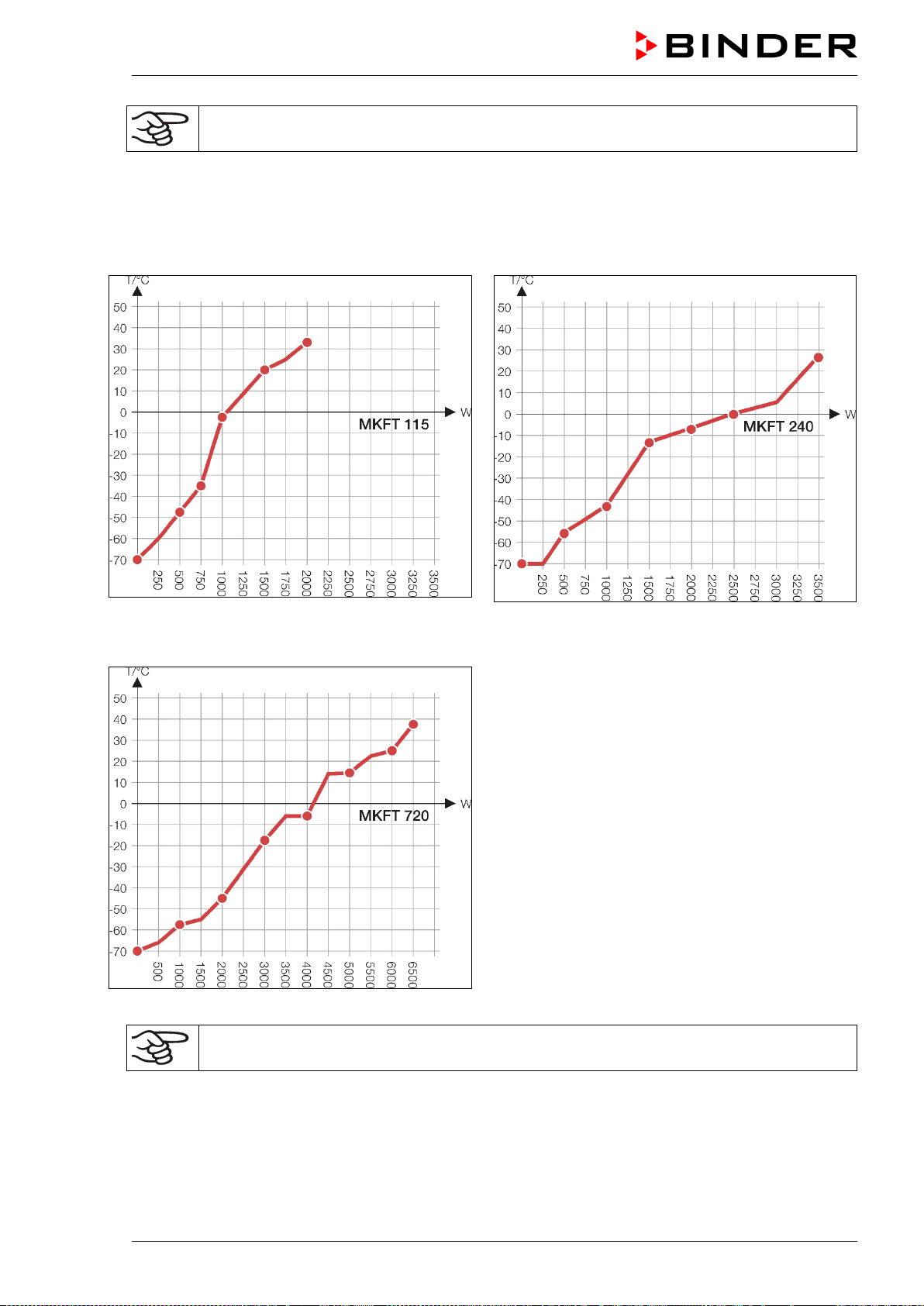
MKF / MKFT (E5) 06/2020 page 155/176
Bringing in a heat load leads to continuous operation of refrigerating machine. In this case
frequent maintenance intervals are necessary.
25.11 MKFT heat compensation graphs
MKFT 115 heat compensation
MKFT 240 heat compensation
MKFT 720 heat compensation
Bringing in a heat load leads to continuous operation of refrigerating machine. In this case
frequent maintenance intervals are necessary.
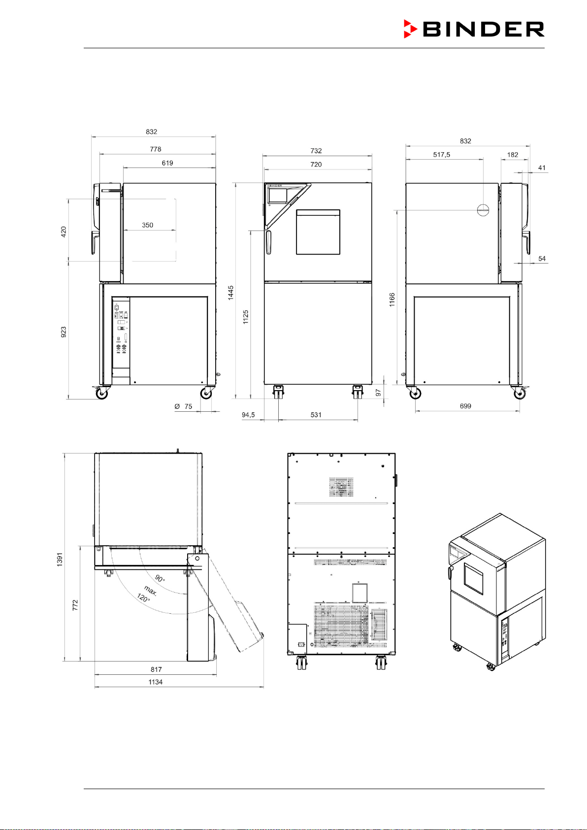
MKF / MKFT (E5) 06/2020 page 156/176
25.12 Dimensions
MKF 56 dimensions:
[mm]
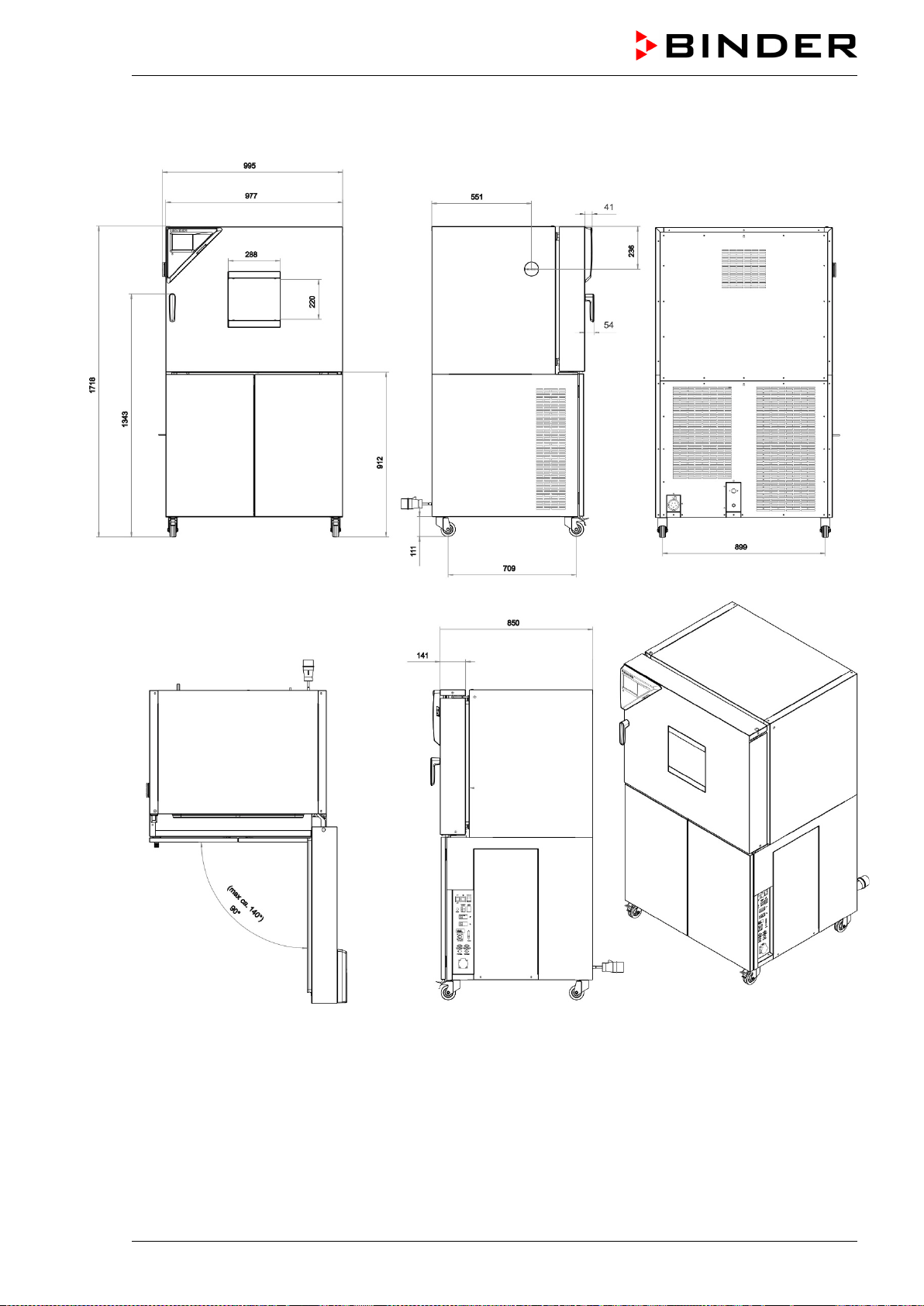
MKF / MKFT (E5) 06/2020 page 157/176
MKF / MKFT 115 dimensions:
[mm]
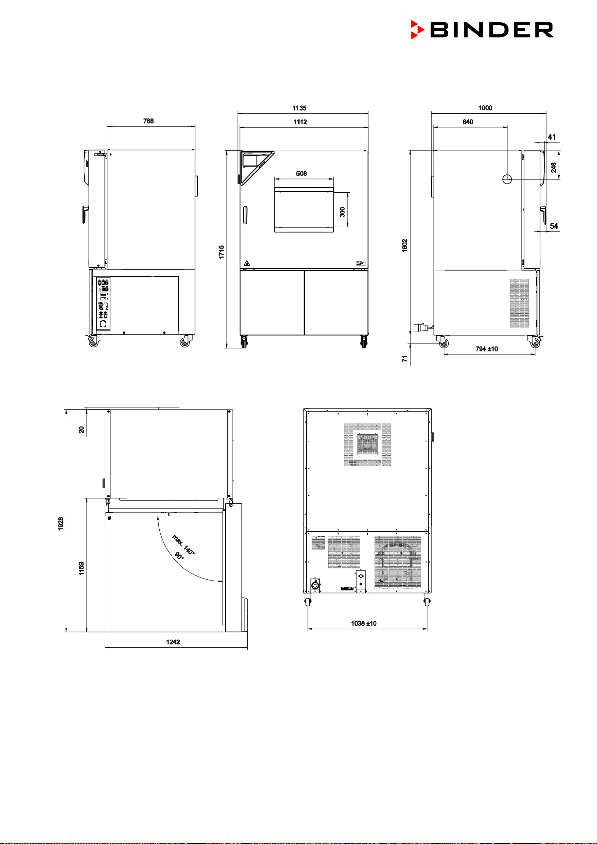
MKF / MKFT (E5) 06/2020 page 158/176
MKF 240 dimensions:
[mm]
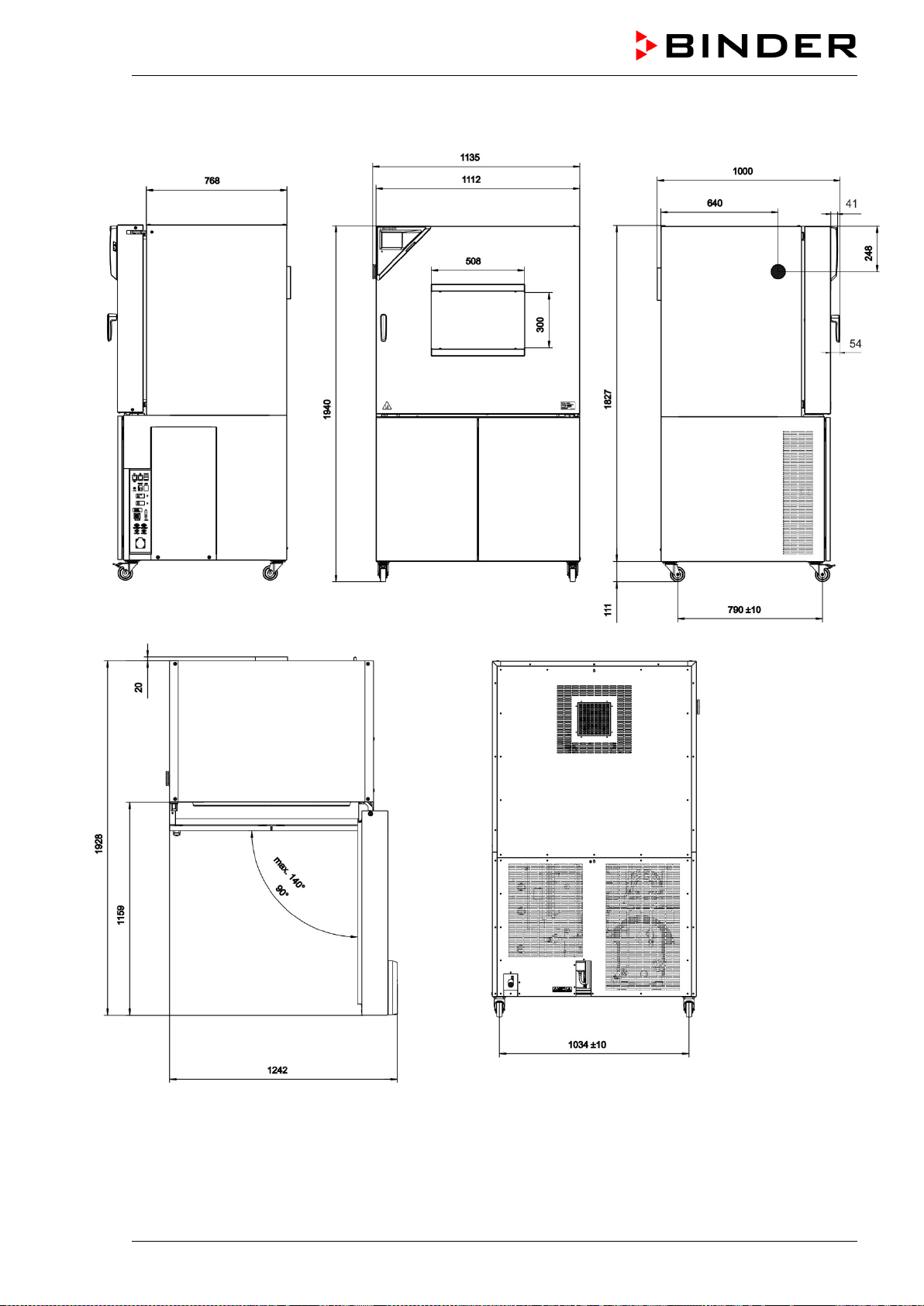
MKF / MKFT (E5) 06/2020 page 159/176
MKFT 240 dimensions:
[mm]
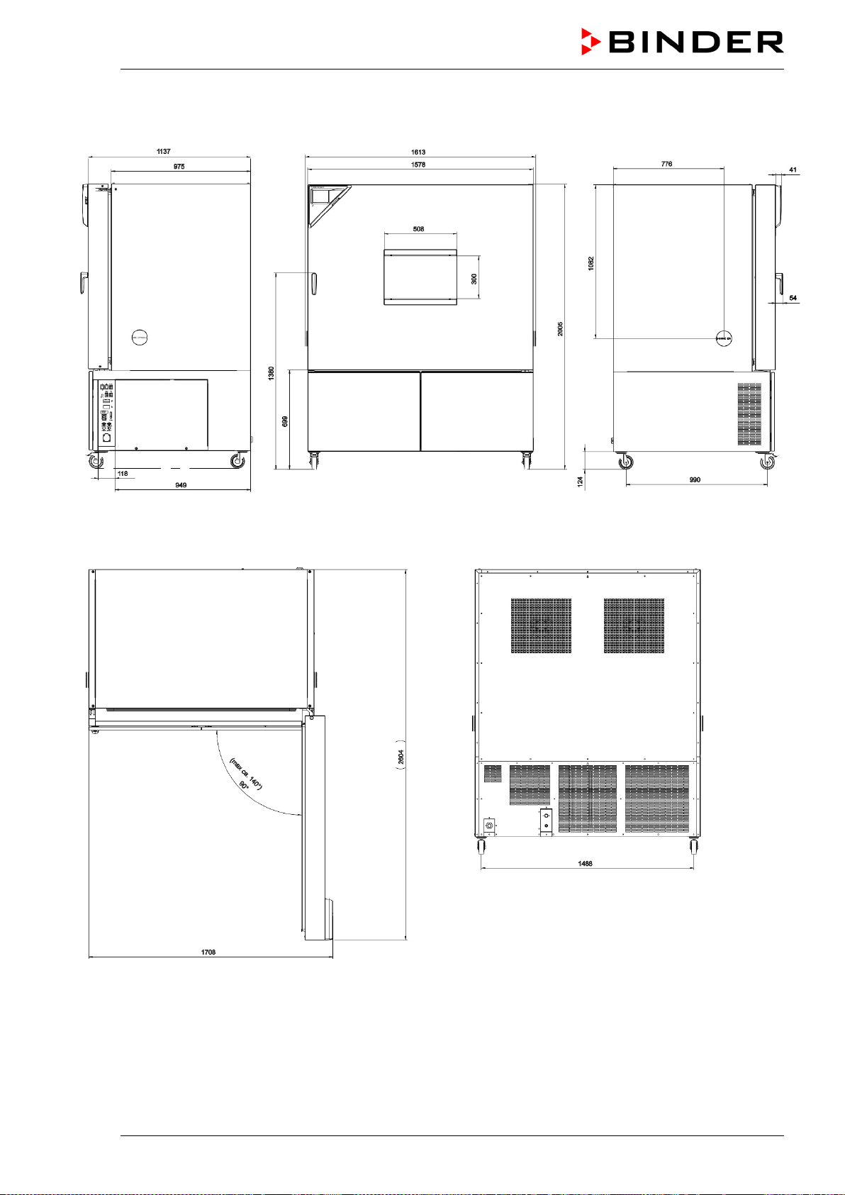
MKF / MKFT (E5) 06/2020 page 160/176
MKF / MKFT 720 dimensions:
[mm]
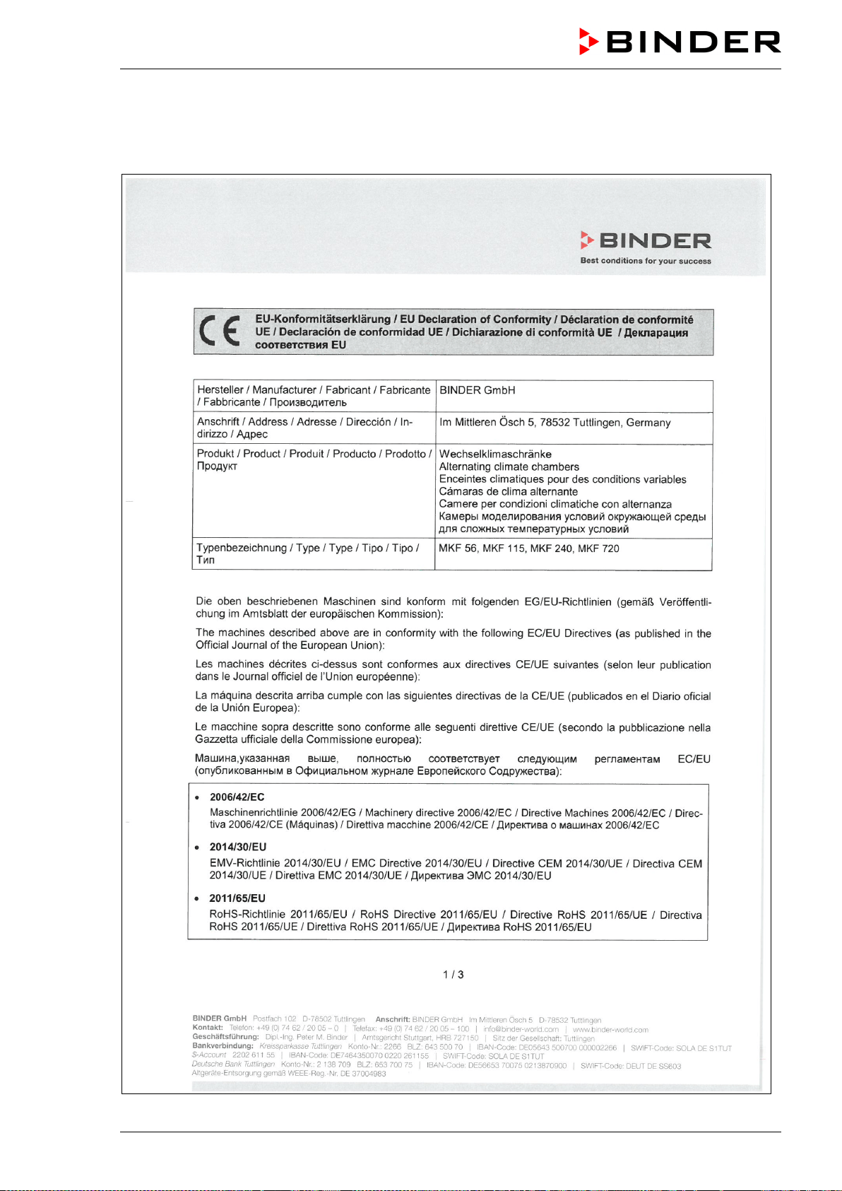
MKF / MKFT (E5) 06/2020 page 161/176
26. Certificates and declarations of conformity
26.1 EU Declaration of Conformity for MKF
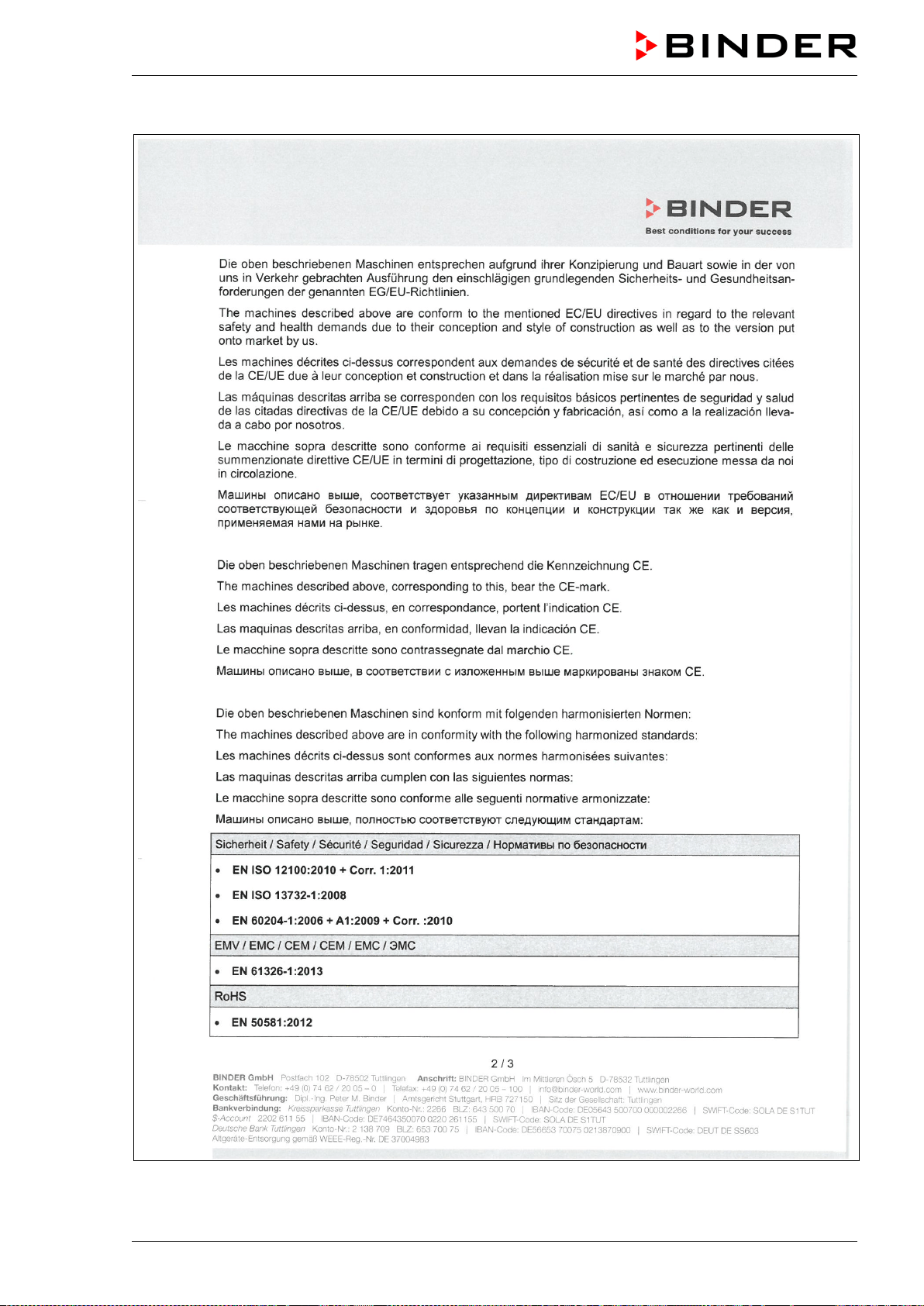
MKF / MKFT (E5) 06/2020 page 162/176
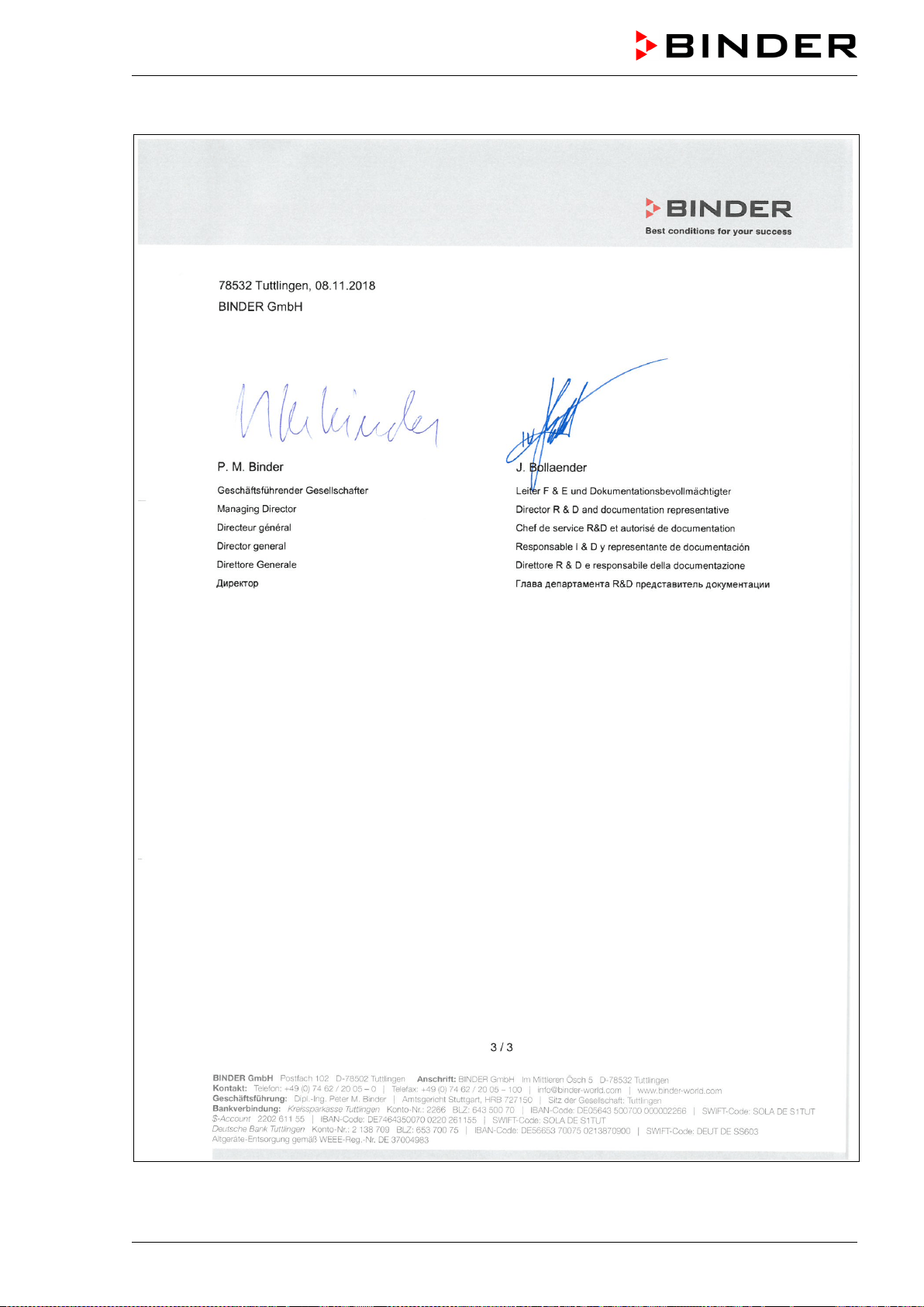
MKF / MKFT (E5) 06/2020 page 163/176
MKF / MKFT (E5) 06/2020 page 164/176
26.2 EU Declaration of Conformity for MKFT
MKF / MKFT (E5) 06/2020 page 165/176
MKF / MKFT (E5) 06/2020 page 166/176
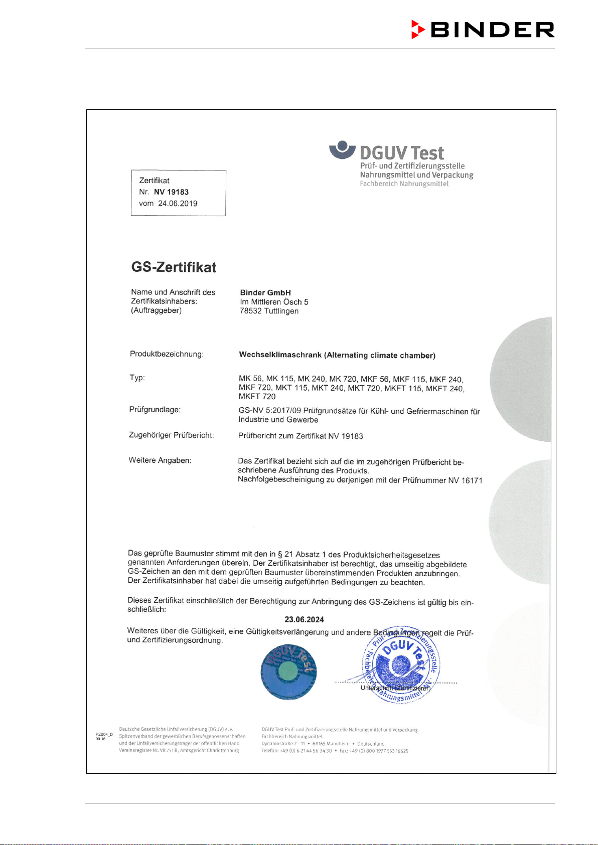
MKF / MKFT (E5) 06/2020 page 167/176
26.3 Certificate for the GS mark of conformity of the “Deutsche Gesetzliche Un-
fallversicherung e.V.“ (German Social Accident Insurance) DGUV
MKF / MKFT (E5) 06/2020 page 168/176
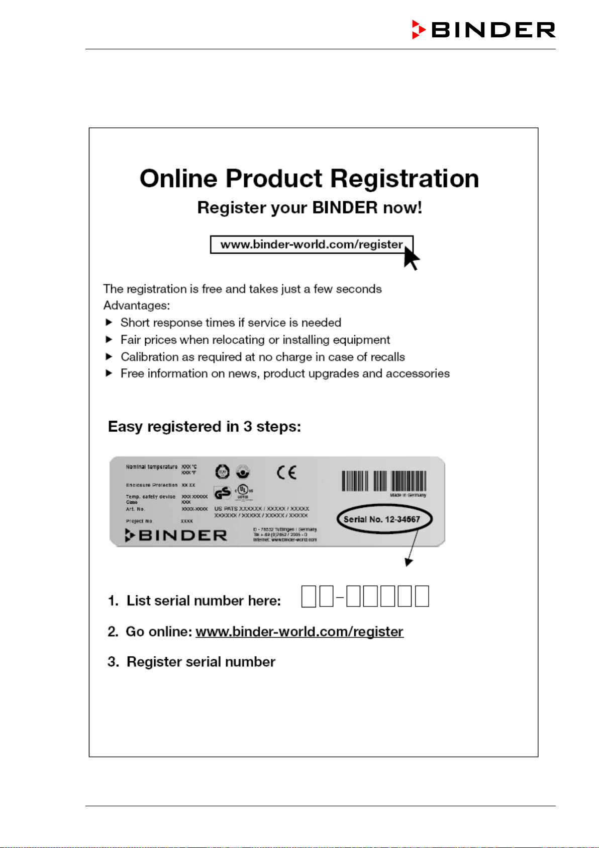
MKF / MKFT (E5) 06/2020 page 169/176
27. Product registration
27.1 Registering a BINDER chamber
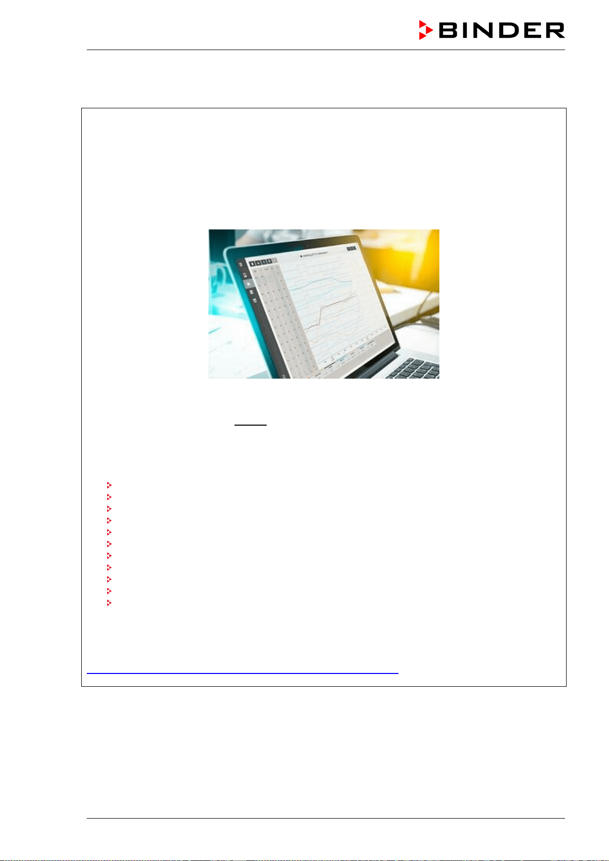
MKF / MKFT (E5) 06/2020 page 170/176
27.2 Multi Management Software APT-COM™ 4 BASIC-Edition
Register now for getting your free
BINDER Multi Management Software
APT-COM™ 4 BASIC-Edition
With the purchase of your BINDER chamber you will receive the BINDER Multi Management Software
APT-COM4™ 4 BASIC-Edition for free.
BINDER´s new Multi Management Software provides management, logging, programming and docu-
mentation options and much more.
Important characteristics of APT-COM™ 4 BASIC-Edition:
Administration of up to five connected chambers
Log management (creating, deleting, archiving)
Documentation of recording values
Central overview of all chambers in both graphic and tabular form
Graphical presentation of recording values
Graphical/numerical program editor
Manual export of recording values (CSV/PDF file)
Multilingual user interface (German, English, French, Spanish, Italian)
Optional program execution via APT-COM™
Timer function
Import of data from APT-COM™ 3
Register your chamber today and request your personal software serial number.
Click here to register:
https://www.binder-world.com/en/service-support/product-registration
MKF / MKFT (E5) 06/2020 page 171/176
28. Contamination clearance certificate
28.1 For chambers located outside the USA and Canada
Declaration regarding safety and health
Erklärung zur Sicherheit und gesundheitlichen Unbedenklichkeit
The German Ordinance on Hazardous Substances (GefStofV), and the regulations regarding safety at
the workplace, require that this form be filled out for all products that are returned to us, so that the safety
and the health of our employees can be guaranteed.
Die Sicherheit und Gesundheit unserer Mitarbeiter, die Gefahrstoffverordnung GefStofV und die Vorschriften zur
Sicherheit am Arbeitsplatz machen es erforderlich, dass dieses Formblatt für alle Produkte, die an uns zurückge-
schickt wird.
Note: A repair is not possible without a completely filled out form.
Ohne Vorliegen des vollständig ausgefüllten Formblattes ist eine Reparatur nicht möglich.
• A completely filled out form must be transmitted via Fax (+49 (0) 7462 2005 93555) or by letter in
advance, so that this information is available before the equipment/component part arrives. A second
copy of this form must accompany the equipment/component part. In addition, the carrier should be in-
formed.
Eine vollständig ausgefüllte Kopie dieses Formblattes soll per Telefax (Nr. +49 (0) 7462 2005 93555) oder Brief
vorab an uns gesandt werden, so dass die Information vorliegt, bevor das Gerät/Bauteil eintrifft. Eine weitere Ko-
pie soll dem Gerät/Bauteil beigefügt sein. Ggf. ist auch die Spedition zu informieren.
• Incomplete information or non-conformity with this procedure will inevitably lead to substantial delays
in processing. Please understand the reason for this measure, which lies outside our area of influence
and will help us to speed up this procedure.
Unvollständige Angaben oder Nichteinhalten dieses Ablaufs führen zwangsläufig zu beträchtlichen Verzögerun-
gen in der Abwicklung. Bitte haben Sie Verständnis für Maßnahmen, die außerhalb unserer Einflussmöglichkeiten
liegen und helfen Sie mit, den Ablauf beschleunigen.
• Please print and fill out this form completely.
Bitte unbedingt vollständig ausfüllen!
1. Unit/ component part / type: / Gerät / Bauteil / Typ:
2. Serial No./ Serien-Nr.:
3. Details about utilized substances / biological substances / Einzelheiten über die eingesetzten
Substanzen/biologische Materialien:
3.1 Designations / Bezeichnungen:
a) ____________________________________________________________________________
b) ____________________________________________________________________________
c) ____________________________________________________________________________
3.2 Safety measures required for handling these substances / Vorsichtsmaßnahmen beim Um-
gang mit diesen Stoffen:
a) ____________________________________________________________________________
b) ____________________________________________________________________________
c) ____________________________________________________________________________
MKF / MKFT (E5) 06/2020 page 172/176
3.3 Measures to be taken in case of skin contact or release into the atmosphere / Maßnahmen
bei Personenkontakt oder Freisetzung:
a) ____________________________________________________________________________
b) ____________________________________________________________________________
c) ____________________________________________________________________________
d) ____________________________________________________________________________
3.4 Other important information that must be taken into account / Weitere zu beachtende und
wichtige Informationen:
a) ____________________________________________________________________________
b) ____________________________________________________________________________
c) ____________________________________________________________________________
4. Declaration on the risk of these substances (please checkmark the applicable items) /
Erklärung zur Gefährlichkeit der Stoffe (bitte Zutreffendes ankreuzen) :
4.1 For non toxic, non radioactive, biologically harmless materials / für nicht giftige, nicht radio-
aktive, biologisch ungefährliche Stoffe:
We hereby guarantee that the above-mentioned unit / component part… /
Wir versichern, dass o.g.
Gerät/Bauteil...
Has not been exposed to or contains any toxic or otherwise hazardous substances /
weder giftige noch
sonstige gefährliche Stoffe enthält oder solche anhaften.
That eventually generated reaction products are non-toxic and also do not represent a hazard /
auch
evtl. entstandene Reaktionsprodukte weder giftig sind noch sonst eine Gefährdung darstellen.
Eventual residues of hazardous substances have been removed /
evtl. Rückstände von Gefahrstoffen
entfernt wurden.
4.2 For toxic, radioactive, biologically harmful or hazardous substances, or any other ha-
zardous materials /
für giftige, radioaktive, biologisch bedenkliche bzw. gefährliche Stoffe oder
anderweitig gefährliche Stoffe.
We hereby guarantee that … /
Wir versichern, dass …
The hazardous substances, which have come into contact with the above-
mentioned
equipment/component part, have been completely listed under item 3.1 and that all information in this
regard is complete / die gefährlichen Stoffe, die mit dem o.g. Gerät/Bauteil
in Kontakt kamen, in 3.1 aufgelistet
sind und alle Angaben vollständig sind.
That the unit /component part has not been in contact with radioactivity /
das Gerät/Bauteil nicht mit Ra-
dioaktivität in Berührung kam
5. Kind of transport / transporter / Transportweg/Spediteur:
Transport by (means and name of transport company, etc.)
Versendung durch (Name Spediteur o.ä.)
___________________________________________________________________________________
Date of dispatch to BINDER GmbH /
Tag der Absendung an BINDER GmbH:
___________________________________________________________________________________
MKF / MKFT (E5) 06/2020 page 173/176
We hereby declare that the following measures have been taken / Wir erklären, dass folgende
Maßnahmen getroffen wurden:
Hazardous substances were removed from the unit including component parts, so that no hazard ex-
ists for any person in the handling or repair of these items /
das Gerät/Bauteil wurde von Gefahrstoffen be-
freit, so dass bei Handhabung/Reparaturen für die betreffenden Person keinerlei Gefährdung besteht
The unit was securely packaged and properly identified /
das Gerät wurde sicher verpackt und vollständig
gekennzeichnet.
Information about the hazardousness of the shipment (if required) has been provided to the transpor-
ter /
der Spediteur wurde (falls vorgeschrieben) über die Gefährlichkeit der Sendung informiert.
We hereby commit ourselves and guarantee that we will indemnify BINDER GmbH for all damages that
are a consequence of incomplete or incorrect i
nformation provided by us, and that we will exempt
BINDER GmbH from eventual damage claims by third parties./
Wir versichern, dass wir gegenüber BINDER
für jeden Schaden, der durch unvollständige und unrichtige Angaben entsteht, haften und BINDER gegen eventuell
entstehende Schadenansprüche Dritter freistellen.
We are aware that, in accordance with Article 823 of the German Civil Code (BGB), we are directly liable
with regard to third parties, in this instance especially the employees of BINDER GmbH, who
have been
entrusted with the handling / repair of the unit / component. / Es ist uns bekannt, dass wir gegenüber Dritten –
hier insbesondere mit der Handhabung/Reparatur des Geräts/des Bauteils betraute Mitarbeiter der Firma BINDER -
gemäß §823 BGB direkt haften
Name: _______________________________________________________________________
Position/Title: _______________________________________________________________________
Date /
Datum: _______________________________________________________________________
Signature /
Unterschrift: _______________________________________________________________
Company stamp /
Firmenstempel:
Equipment that is returned to the factory for repair must be accompanied by a completely filled
out contamination clearance certificate. For service and maintenance on site, such a contami-
nation clearance certificate must be submitted to the service technician before the start of any
work. No repair or maintenance of the equipment is possible, without a properly filled out con-
tamination clearance certificate.
MKF / MKFT (E5) 06/2020 page 174/176
28.2 For chambers located in the USA and Canada
Product Return Authorization Request
Please complete this form and the Customer Decontamination Declaration (next 2 pages) and attach the
required pictures. E-mail to: IDL_SalesOrderProcessing_USA@binder-world.com
After we have received and reviewed the complete information we will decide on the issue of a RMA
number. Please be aware that size specifications, voltage specifications as well as performance specifi-
cations are available on the internet at
www.binder-world.us at any time.
Take notice of shipping laws and regulations.
Please fill:
Reason for return request Duplicate order
Duplicate shipment
Demo Page one completed by sales
Power Plug / Voltage 115V / 230 V / 208 V / 240V
Size does not fit space
Transport Damage Shock watch tripped? (pictures)
Other (specify below)
_____________________
Is there a replacement PO? Yes No
If yes -> PO #
If yes -> Date PO placed
Purchase order number
BINDER model number
BINDER serial number
Date unit was received
Was the unit unboxed? Yes No
Was the unit plugged in? Yes No
Was the unit in operation? Yes No
Pictures of unit attached?
Pictures of Packaging at-
tached?
Yes No
Yes No
Pictures have to be attached!
Customer Contact Information Distributor Contact Information
Name
Company
Address
Phone
E-mail
MKF / MKFT (E5) 06/2020 page 175/176
Customer (End User) Decontamination Declaration
Health and Hazard Safety declaration
To protect the health of our employees and the safety at the workplace, we require that this form is com-
pleted by the user for all products and parts that are returned to us. (Distributors or Service Organizations
cannot sign this form)
NO RMA number will be issued without a completed form. Products or parts returned to our
NY warehouse without a RMA number will be refused at the dock.
A second copy of the completed form must be attached to the outside of the shipping box.
1. Unit/ component part / type
:
2. Serial No.
3. List any exposure to hazardous liquids, gasses or substances and radioactive material
3.1 List with MSDS sheets attached where available or needed
(if there is not enough space available below, please attach a page):
a) ____________________________________________________________________________
b) ____________________________________________________________________________
c) ____________________________________________________________________________
3.2 Safety measures required for handling the list under 3.1
a) ____________________________________________________________________________
b) ____________________________________________________________________________
c) ____________________________________________________________________________
3.3 Measures to be taken in case of skin contact or release into the atmosphere
:
a) ____________________________________________________________________________
b) ____________________________________________________________________________
c) ____________________________________________________________________________
d) ____________________________________________________________________________
3.4 Other important information that must be considered
:
a) ____________________________________________________________________________
b) ____________________________________________________________________________
c) ____________________________________________________________________________
MKF / MKFT (E5) 06/2020 page 176/176
4. Declaration of Decontamination
For toxic, radioactive, biologically and chemically harmful or hazardous substances, or any other
hazardous materials.
We hereby guarantee that
4.1 Any hazardous substances, which have come into contact with the above-mentioned equipment /
component part, have been completely listed under item 3.1 and that all information in this regard is
complete
.
4.2 That the unit /component part has not been in contact with radioactivity
4.3 A
ny Hazardous substances were removed from the unit / component part, so that no hazard exists
for a persons in the shipping, handling or repair of these returned unit
4.4 The unit was securely packaged in the original undamaged packaging and properly iden
tified on the
outside of the packaging material with the unit designation, the RMA number and a copy of this dec-
laration.
4.5 Shipping laws and regulations have not been violated.
I hereby commit and guarantee that we will indemnify BINDER Inc. for all damages that are a
consequence of incomplete or incorrect information provided by us, and that we will indemnify
and hold harmless BINDER Inc. from eventual damage claims by third parties.
N
ame: _______________________________________________________________________
Position: _______________________________________________________________________
Company: _______________________________________________________________________
Address: _______________________________________________________________________
Phone #: _______________________________________________________________________
Email: _______________________________________________________________________
Date: _______________________________________________________________________
Signature: ________________________________________________________________________
E
quipment returned to the NY warehouse for repair must be accompanied by a completed
customer decontamination declaration. For service and maintenance works on site, such a
customer decontamination declaration must be submitted to the service technician before the
start of work. No repair or maintenance of the equipment is possible without a completed form.