Loading ...
Loading ...
Loading ...
©2013-2016 DJI. All Rights Reserved. 8
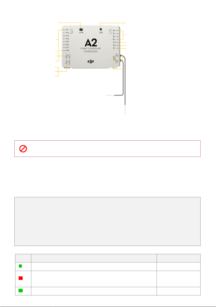
Port Description
Connect to ESC
iOSD MARK II, Z15 from DJI
IMU
GPS-COMPASS PRO PLUS
To PW port of PMU
LED-BT-I
2.4G DATA LINK from DJI
To parachute
To S-BUS Receiver
BEC,Connect to X1 of PMU for voltage detection
To DSM2 satellite Receiver
Antenna
Indicate the linking status
Link button of Built-in receiver
DR16 and transmitter
Multi-function PWM output channels, can directly give
output signal from the Receiver if mapped to a
Receiver channel*
*If the Gimbal function is enabled in Assistant Software,
F2/F3 can only be used for gimbal Pitch/Roll control,
which means F2/F3 cannot be mapped to any other
Receiver channel.
*If the Gear function is enabled in Assistant Software,
F1 can only be used for gear switch control, which
means F1 cannot be mapped to any other Receiver
channel.
Mounting Requirements:
Install the Controller Unit in the proper position to make sure the ports are accessible. No specified direction is
required.
Place the antennas in an open space under the aircraft, DO NOT block them. Position the heads of
two antennas at a 90-degree angle. DO NOT bend or wind them.
Receiver System
The A2 flight control system can use its own built-in Receiver, and also can support external receivers. Whatever
type of Receiver is used, please make sure that the Receiver and Transmitter is linked correctly before use.
A. Built-in Receiver
For enhancing the system integration and reliability, the A2 is integrated with a 2.4G receiver based on
frequency hopping technology. The built-in Receiver can be used with the Transmitter of Futaba FASST series
or DJI DESST series after linking. For users, you are only asked to carry out the link procedures, no extra
requirement for connection.
Please carry out the following procedures to finish the Link process, and the configuration in the A2 Assistant
software->Basic ->R/C ->Receiver Type. Select the DR16 option.
During use, you may see the following LED indication, please do the operation according to the table below.
LED
Description
Operation
(∝)
Signal from Transmitter has been detected by the Receiver, but not matched.
Link operation required
(∝)
No Transmitter signal is received, e.g. the flight control system is powered on
but the Transmitter is powered off.
Switch on
(∝)
The Receiver and Transmitter have been linked to each other successfully.
Can work normally
Loading ...
Loading ...
Loading ...