Loading ...
Loading ...
Loading ...
©2013-2016 DJI. All Rights Reserved. 14
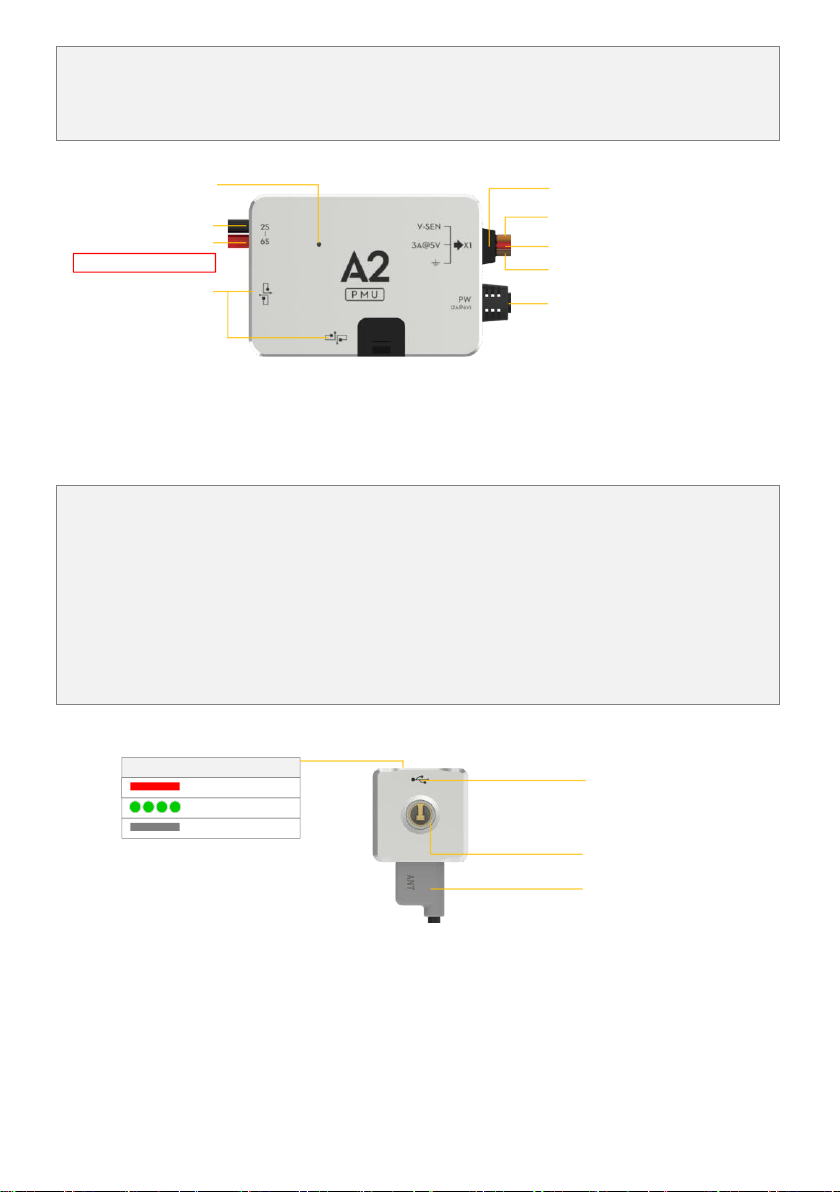
(2) PX port outputs power (3A@5V) and V-SEV signal using the low voltage protection function.
In addition, there are two CAN-Bus ports for LED-BT-I connection and other DJI products (e.g. DJI 2.4G Data
Link).
Port Description
To positive pole of power
To negative pole of power
CAN-Bus port
Connect to CAN1 or CAN2 port of
Controller Unit, CAN2 is recommended.
V-SEN, Output 0V ~ + 3.3V
VCC, Output 3A@5V
GND
Input voltage range: 7.4V~26V
PX Port, connect to the X1 port of
Controller Unit
Working status indicator
Green on is normally working
Mounting Requirements:
Choose a ventilated place to mount the PMU for cooling, no mounting orientation requirement.
(5) LED-BT-I
The LED-BT-I has integrated LED Indicator, Bluetooth and USB port:
(1) The LED is mainly for flight control system status indication during flying (e.g. Control Mode).
(2) Bluetooth is used for real-time communication with your mobile device (e.g. iPhone), to realize parameter
configuration on a mobile device. For parameter configuration using a mobile device, it is required to
install the DJI Assistant App on the mobile device. When you mount the LED-BT-I, please make sure the
side with ANT LOGO is unsheltered after mounting.
(3) In addition, there is a Micro-USB port, make sure it is mounted for convenient connection.
Port Description:
Micro-USB port:used to
connect to the PC for Assistant
software configuration and
upgrade
Bluetooth status indicator
Abnormal
Normal
Communicating
Indicator of autopilot system
Antenna of Bluetooth
Mounting Requirements:
Mount in a good place to make sure the LED is visible during flying. Antenna of Bluetooth should be unobstructed.
Loading ...
Loading ...
Loading ...