Loading ...
Loading ...
Loading ...
©2013-2016 DJI. All Rights Reserved. 5
System Introduction
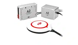
The A2 flight control system uses the Controller Unit at its core, which is connected with the IMU,
GPS-COMPASS PRO PLUS、LED-BT-I、PMU and ESCs to complete the system. The system can achieve the
height-lock and position-lock functions by using the IMU and the GPS, to control the aircraft.
Please carry out the following procedures to finish assembly, configuration and flight-testing.
Symbol Instruction
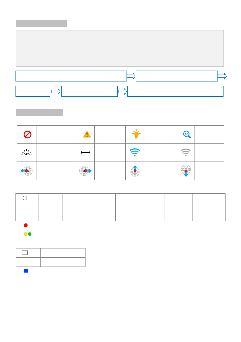
General Symbol
Forbidden(Important)
Cautions
Tips
Reference
GPS Satellite number
Distance
TX signal good
TX signal lost
Roll to left
Roll to right
Pitch up
Pitch down
LED Symbol
(N)
N=1
N=2
N=3
N=4
N=6
N=20
N=∝
Meaning
One Blink
Two Blinks
Three Blinks
Four Blinks
Six Blinks
Twenty Blinks
Continuous
Blinks
e.g. (3) means three Red blinks.
(∝)LED blinks yellow and green alternatively.
(N)
N=∝
Meaning
Continuous Solid on
e.g. (∝) means Continuous Blue Solid on.
Configure the system using A2 Assistant software.
Basic flying test
FailSafe and Low-voltage settings
Advanced functions: IOC, Gimbal, Gear
Mount the A2 flight control system on your aircraft finish connection.
Loading ...
Loading ...
Loading ...