Loading ...
Loading ...
Loading ...
©2013-2016 DJI. All Rights Reserved. 7
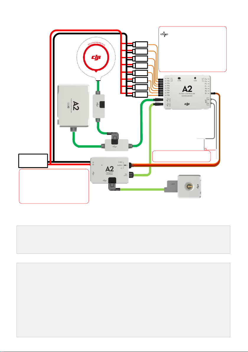
1.1.2 Hardware Connection Diagram
90
o
ESC 1#
ESC 2#
ESC 3#
ESC 4#
ESC 5#
ESC 6#
ESC 7#
ESC 8#
Important
Make sure the cable connections
are tight before every flight.
Suitable amount of hot melt
adhesive is recommended to use in
the connections to the CAN1 and
CAN2 ports.
Important
CAN-Bus, it provides power supply
and communication. A2 can
automatically identify the device
connected.
CAN1 and CAN2 ports are working
independent, device connected are
non-interchangeable. E.g. IMU and GPS-
COMPASS PRO PLUS to CAN1; LED-BT-I
to CAN2; PMU to CAN1 or CAN2.
Supply power for all ports on
both sides of controller unit.
2S~6S
Battery
1.1.3 Important for Assembly and Connection
This section describes all device port functions, assembly requirements, connection requirements and tips
during usage. Also the linking procedures between the built-in Receiver DR16 and your Transmitter. Please read
all information below carefully, especially if you are a first time user.
(1) Controller Unit
The Controller Unit is the core component of the A2 flight control system:
(1) M1~M8 are used to connect to the ESCs of the aircraft.
(2) The built-in Receiver DR16 is based on DJI DESST technology, which can be used with the Futaba FASST
series and DJI DESST series Transmitter.
(3) CAN1 and CAN2 ports are working independently and should connect to different modules.
(4) 4 independent and configurable outputs.
(5) It is compatible with the external Receiver, e.g. DSM2 satellite Receiver.
(6) Use the optional DJI DBUS Adapter to support the traditional receiver.
Loading ...
Loading ...
Loading ...