Loading ...
Loading ...
Loading ...
709/709H/710
Users Manual
38
Test Configuration Screens
Use the configuration screens to set the default tolerance of the
tests:
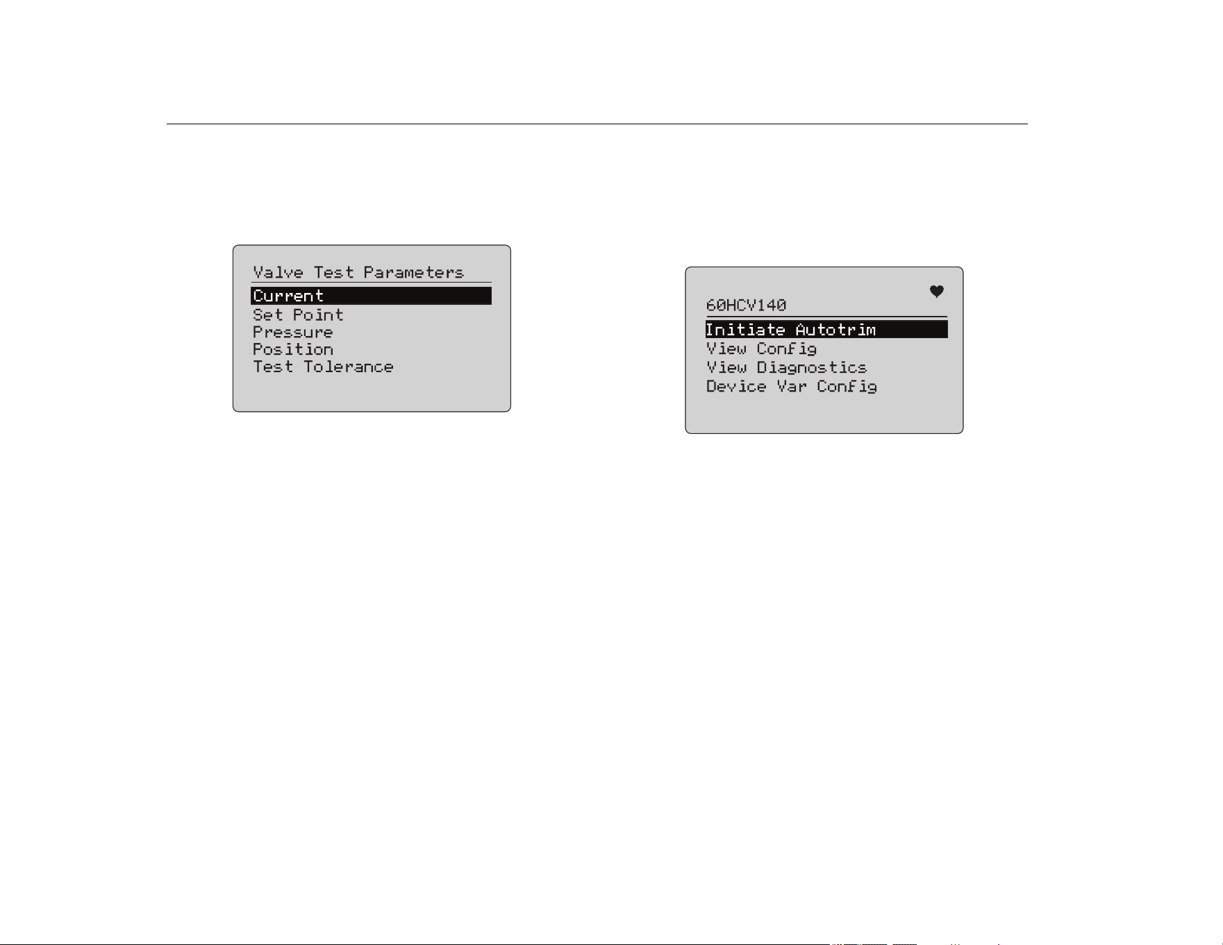
1. In the calibrator Setup Menu (see Figure 9), select Valve Test
Parameters to review the variable mapping. See Figure 57.
Figure 57. Valve Tests
To set the Test Tolerance:
1. Go to Valve Test Parameters > Test Tolerances.
2. Change the individual test tolerances from 1 % to 20 %.
HART Comms Menu
Use the HART Comms Menu to start autotrim and view device
variables and status:
1. Connect to the HART valve.
2. Go to Modify Setup > HART Comms. See Figure 58 for the
available options.
Figure 58. HART Comms. Menu
• Initiate Autotrim: Use to autotrim the positioner. At the
end of the autotrim, the valve position is set to 50 % and
you can quickly decide if additional trimming is required.
• View Config: Supports only HART 7 devices. Use to
show the device variable classification of PV, SV, TV and
QV. Examples include:
• Pressure
• Volume Flow
•Mass Flow
If HART 7 is not supported by the device, the display
shows a warning message.
• View Diagnostics: Supports only HART 7 devices. Use to
show the status of the PV, SV, TV, and QV variables (for
example, BAD, MARGINAL, or GOOD). If HART 7 is not
supported by the device, the display shows a warning
message.
• Device Var Config: Use to view the PV, SV, TV and QV
variables of the device.
1.888.610.7664 sales@GlobalTestSupply.com
Fluke-Direct.com
Loading ...
Loading ...
Loading ...