
Loading ...
Loading ...
Loading ...
Precision Loop Calibrator
Calibrator Setup Menu
15
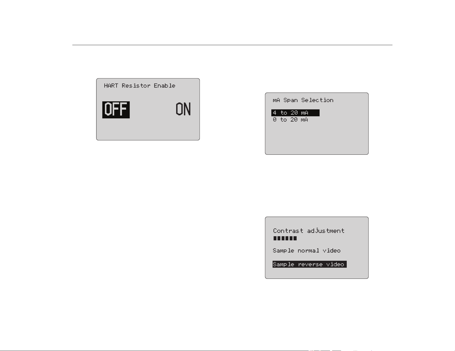
HART 250Ω Resistor
The HART 250Ω Resistor Enable function turns on and turns off
the HART resistor. See the HART Resistor. See Figure 14.
Figure 14. HART Resistor Enable Screen
The Product can insert a 250 Ω resistor in series with the power
supply in order to use a HART communicator. The HART resistor
is enabled through the menu.
To get to the second Calibrator Setup Screen, highlight Other
Parameters and push the selection knob.
Valve Test Parameters
Use the Valve Test Parameters menu to set the 710 parameters
to match the valve parameters (for example, PV, SV, TV, and QV).
This menu also sets the default test tolerances for all test
templates.
mA Span
mA Span is the first item on the second Calibrator Setup Menu.
The mA Span function sets the step interval for the mA Auto Step
feature. The value can be set from 5 seconds to 300 seconds. See
Step and Ramp Operation. See Figure 15.
Figure 15. mA Span Selection Screen
Contrast
The Contrast function adjusts the display contrast. Turn the
selection knob to adjust the contrast. The range shows by the bar
graph. Higher contrast shows by a longer bar. The sample normal
and reverse video selections let you evaluate both text modes.
See Figure 16.
Figure 16. Contrast Adjustment Screen
1.888.610.7664 sales@GlobalTestSupply.com
Fluke-Direct.com
Loading ...
Loading ...
Loading ...