
January 2013 Rev. 1 10/18
©2013-2018 Fluke Corporation. All rights reserved.
All product names are trademarks of their respective companies.
Specifications are subject to change without notice.
709/709H/710
Precision Loop Calibrator
Users Manual
1.888.610.7664 sales@GlobalTestSupply.com
Fluke-Direct.com

LIMITED WARRANTY AND LIMITATION OF LIABILITY
This Fluke product will be free from defects in material and workmanship for three years from the date of purchase. This warranty does not cover
fuses, disposable batteries, or damage from accident, neglect, misuse, alteration, contamination, or abnormal conditions of operation or handling.
Resellers are not authorized to extend any other warranty on Fluke’s behalf. To obtain service during the warranty period, contact your nearest
Fluke authorized service center to obtain return authorization information, then send the product to that Service Center with a description of the
problem.
THIS WARRANTY IS YOUR ONLY REMEDY. NO OTHER WARRANTIES, SUCH AS FITNESS FOR A PARTICULAR PURPOSE, ARE
EXPRESSED OR IMPLIED. FLUKE IS NOT LIABLE FOR ANY SPECIAL, INDIRECT, INCIDENTAL OR CONSEQUENTIAL DAMAGES OR
LOSSES, ARISING FROM ANY CAUSE OR THEORY. Since some states or countries do not allow the exclusion or limitation of an implied
warranty or of incidental or consequential damages, this limitation of liability may not apply to you.
11/99
1.888.610.7664 sales@GlobalTestSupply.com
Fluke-Direct.com

i
Title Page
Introduction . . . . . . . . . . . . . . . . . . . . . . . . . . . . . . . . . . . . . . . . . . . . . . . . . . . . . . . . . . . . . . . . . . . . . . . . . . . . . . . . . . . . . . . . . 1
How to Contact Fluke . . . . . . . . . . . . . . . . . . . . . . . . . . . . . . . . . . . . . . . . . . . . . . . . . . . . . . . . . . . . . . . . . . . . . . . . . . . . . . . . . 2
Safety Information. . . . . . . . . . . . . . . . . . . . . . . . . . . . . . . . . . . . . . . . . . . . . . . . . . . . . . . . . . . . . . . . . . . . . . . . . . . . . . . . . . . . 2
Symbols . . . . . . . . . . . . . . . . . . . . . . . . . . . . . . . . . . . . . . . . . . . . . . . . . . . . . . . . . . . . . . . . . . . . . . . . . . . . . . . . . . . . . . . . . . . 3
Standard Equipment . . . . . . . . . . . . . . . . . . . . . . . . . . . . . . . . . . . . . . . . . . . . . . . . . . . . . . . . . . . . . . . . . . . . . . . . . . . . . . . . . . 4
The Product . . . . . . . . . . . . . . . . . . . . . . . . . . . . . . . . . . . . . . . . . . . . . . . . . . . . . . . . . . . . . . . . . . . . . . . . . . . . . . . . . . . . . . . . 6
The Buttons . . . . . . . . . . . . . . . . . . . . . . . . . . . . . . . . . . . . . . . . . . . . . . . . . . . . . . . . . . . . . . . . . . . . . . . . . . . . . . . . . . . . . 6
The Selection Knob . . . . . . . . . . . . . . . . . . . . . . . . . . . . . . . . . . . . . . . . . . . . . . . . . . . . . . . . . . . . . . . . . . . . . . . . . . . . . . . 7
Language Selection . . . . . . . . . . . . . . . . . . . . . . . . . . . . . . . . . . . . . . . . . . . . . . . . . . . . . . . . . . . . . . . . . . . . . . . . . . . . . . . 7
Main Menu . . . . . . . . . . . . . . . . . . . . . . . . . . . . . . . . . . . . . . . . . . . . . . . . . . . . . . . . . . . . . . . . . . . . . . . . . . . . . . . . . . . . . . . . . 7
mA Source . . . . . . . . . . . . . . . . . . . . . . . . . . . . . . . . . . . . . . . . . . . . . . . . . . . . . . . . . . . . . . . . . . . . . . . . . . . . . . . . . . . . . . 8
mA Simulate . . . . . . . . . . . . . . . . . . . . . . . . . . . . . . . . . . . . . . . . . . . . . . . . . . . . . . . . . . . . . . . . . . . . . . . . . . . . . . . . . . . . 9
mA Measure . . . . . . . . . . . . . . . . . . . . . . . . . . . . . . . . . . . . . . . . . . . . . . . . . . . . . . . . . . . . . . . . . . . . . . . . . . . . . . . . . . . 10
mA Measure with 24V . . . . . . . . . . . . . . . . . . . . . . . . . . . . . . . . . . . . . . . . . . . . . . . . . . . . . . . . . . . . . . . . . . . . . . . . . . . . 11
Volts Measure . . . . . . . . . . . . . . . . . . . . . . . . . . . . . . . . . . . . . . . . . . . . . . . . . . . . . . . . . . . . . . . . . . . . . . . . . . . . . . . . . . 12
Calibrator Setup Menu . . . . . . . . . . . . . . . . . . . . . . . . . . . . . . . . . . . . . . . . . . . . . . . . . . . . . . . . . . . . . . . . . . . . . . . . . . . . . . . 12
Auto Ramp Time . . . . . . . . . . . . . . . . . . . . . . . . . . . . . . . . . . . . . . . . . . . . . . . . . . . . . . . . . . . . . . . . . . . . . . . . . . . . . . . . 13
Auto Step Time . . . . . . . . . . . . . . . . . . . . . . . . . . . . . . . . . . . . . . . . . . . . . . . . . . . . . . . . . . . . . . . . . . . . . . . . . . . . . . . . . 13
Step and Ramp Operation . . . . . . . . . . . . . . . . . . . . . . . . . . . . . . . . . . . . . . . . . . . . . . . . . . . . . . . . . . . . . . . . . . . . . . . . . 13
Automatic Step and Ramp . . . . . . . . . . . . . . . . . . . . . . . . . . . . . . . . . . . . . . . . . . . . . . . . . . . . . . . . . . . . . . . . . . . . . . . . . 14
Valve Test . . . . . . . . . . . . . . . . . . . . . . . . . . . . . . . . . . . . . . . . . . . . . . . . . . . . . . . . . . . . . . . . . . . . . . . . . . . . . . . . . . . . . 14
HART 250Ω Resistor . . . . . . . . . . . . . . . . . . . . . . . . . . . . . . . . . . . . . . . . . . . . . . . . . . . . . . . . . . . . . . . . . . . . . . . . . . . . . 15
Valve Test Parameters . . . . . . . . . . . . . . . . . . . . . . . . . . . . . . . . . . . . . . . . . . . . . . . . . . . . . . . . . . . . . . . . . . . . . . . . . . . 15
Table of Contents
1.888.610.7664 sales@GlobalTestSupply.com
Fluke-Direct.com

709/709H/710
Users Manual
ii
mA Span . . . . . . . . . . . . . . . . . . . . . . . . . . . . . . . . . . . . . . . . . . . . . . . . . . . . . . . . . . . . . . . . . . . . . . . . . . . . . . . . . . . . . . 15
Contrast . . . . . . . . . . . . . . . . . . . . . . . . . . . . . . . . . . . . . . . . . . . . . . . . . . . . . . . . . . . . . . . . . . . . . . . . . . . . . . . . . . . . . . . 15
Auto Shutdown Time . . . . . . . . . . . . . . . . . . . . . . . . . . . . . . . . . . . . . . . . . . . . . . . . . . . . . . . . . . . . . . . . . . . . . . . . . . . . . 16
HART Write Enable . . . . . . . . . . . . . . . . . . . . . . . . . . . . . . . . . . . . . . . . . . . . . . . . . . . . . . . . . . . . . . . . . . . . . . . . . . . . . . 16
HART Device Communication . . . . . . . . . . . . . . . . . . . . . . . . . . . . . . . . . . . . . . . . . . . . . . . . . . . . . . . . . . . . . . . . . . . . . . . . . 17
HART Connections . . . . . . . . . . . . . . . . . . . . . . . . . . . . . . . . . . . . . . . . . . . . . . . . . . . . . . . . . . . . . . . . . . . . . . . . . . . . . . 18
In Circuit, External Loop Power . . . . . . . . . . . . . . . . . . . . . . . . . . . . . . . . . . . . . . . . . . . . . . . . . . . . . . . . . . . . . . . . . 18
In Circuit, Product Loop Power. . . . . . . . . . . . . . . . . . . . . . . . . . . . . . . . . . . . . . . . . . . . . . . . . . . . . . . . . . . . . . . . . . 19
Across Circuit, Communicator Only . . . . . . . . . . . . . . . . . . . . . . . . . . . . . . . . . . . . . . . . . . . . . . . . . . . . . . . . . . . . . . 20
Communications Setup and Selection. . . . . . . . . . . . . . . . . . . . . . . . . . . . . . . . . . . . . . . . . . . . . . . . . . . . . . . . . . . . . . . . 21
Mode. . . . . . . . . . . . . . . . . . . . . . . . . . . . . . . . . . . . . . . . . . . . . . . . . . . . . . . . . . . . . . . . . . . . . . . . . . . . . . . . . . . . . . 21
250Ω Resistor. . . . . . . . . . . . . . . . . . . . . . . . . . . . . . . . . . . . . . . . . . . . . . . . . . . . . . . . . . . . . . . . . . . . . . . . . . . . . . . 22
HART Connect . . . . . . . . . . . . . . . . . . . . . . . . . . . . . . . . . . . . . . . . . . . . . . . . . . . . . . . . . . . . . . . . . . . . . . . . . . . . . . 22
Polling Loop . . . . . . . . . . . . . . . . . . . . . . . . . . . . . . . . . . . . . . . . . . . . . . . . . . . . . . . . . . . . . . . . . . . . . . . . . . . . . . . . 22
Tag Selection . . . . . . . . . . . . . . . . . . . . . . . . . . . . . . . . . . . . . . . . . . . . . . . . . . . . . . . . . . . . . . . . . . . . . . . . . . . . . . . 23
Acquiring Data . . . . . . . . . . . . . . . . . . . . . . . . . . . . . . . . . . . . . . . . . . . . . . . . . . . . . . . . . . . . . . . . . . . . . . . . . . . . . . 23
Disconnect from Loop. . . . . . . . . . . . . . . . . . . . . . . . . . . . . . . . . . . . . . . . . . . . . . . . . . . . . . . . . . . . . . . . . . . . . . . . . 24
Function Select Menu . . . . . . . . . . . . . . . . . . . . . . . . . . . . . . . . . . . . . . . . . . . . . . . . . . . . . . . . . . . . . . . . . . . . . . . . . . . . 24
Display Setup and Data . . . . . . . . . . . . . . . . . . . . . . . . . . . . . . . . . . . . . . . . . . . . . . . . . . . . . . . . . . . . . . . . . . . . . . . . . . . 24
Write LRV and URV Values . . . . . . . . . . . . . . . . . . . . . . . . . . . . . . . . . . . . . . . . . . . . . . . . . . . . . . . . . . . . . . . . . . . . . . . . . . . 25
Write LRV . . . . . . . . . . . . . . . . . . . . . . . . . . . . . . . . . . . . . . . . . . . . . . . . . . . . . . . . . . . . . . . . . . . . . . . . . . . . . . . . . . 25
Write URV. . . . . . . . . . . . . . . . . . . . . . . . . . . . . . . . . . . . . . . . . . . . . . . . . . . . . . . . . . . . . . . . . . . . . . . . . . . . . . . . . . 26
Write PV Unit . . . . . . . . . . . . . . . . . . . . . . . . . . . . . . . . . . . . . . . . . . . . . . . . . . . . . . . . . . . . . . . . . . . . . . . . . . . . . . . 26
Modify Tags, Msg, Descr . . . . . . . . . . . . . . . . . . . . . . . . . . . . . . . . . . . . . . . . . . . . . . . . . . . . . . . . . . . . . . . . . . . . . . 27
Trim, Set, and Zero Menu . . . . . . . . . . . . . . . . . . . . . . . . . . . . . . . . . . . . . . . . . . . . . . . . . . . . . . . . . . . . . . . . . . . . . . . . . . . . . 28
Trim 4 mA . . . . . . . . . . . . . . . . . . . . . . . . . . . . . . . . . . . . . . . . . . . . . . . . . . . . . . . . . . . . . . . . . . . . . . . . . . . . . . . . . . . . . 28
Trim 20 mA . . . . . . . . . . . . . . . . . . . . . . . . . . . . . . . . . . . . . . . . . . . . . . . . . . . . . . . . . . . . . . . . . . . . . . . . . . . . . . . . . . . . 29
Set Fixed mA Output . . . . . . . . . . . . . . . . . . . . . . .
. . . . . . . . . . . . . . . . . . . . . . . . . . . . . . . . . . . . . . . . . . . . . . . . . . . . . . 29
PV Zero . . . . . . . . . . . . . . . . . . . . . . . . . . . . . . . . . . . . . . . . . . . . . . . . . . . . . . . . . . . . . . . . . . . . . . . . . . . . . . . . . . . . . . . 30
Device Diagnostic . . . . . . . . . . . . . . . . . . . . . . . . . . . . . . . . . . . . . . . . . . . . . . . . . . . . . . . . . . . . . . . . . . . . . . . . . . . . . . . . . . . 30
Configuration Log and Data Log . . . . . . . . . . . . . . . . . . . . . . . . . . . . . . . . . . . . . . . . . . . . . . . . . . . . . . . . . . . . . . . . . . . . . . . . 31
Configuration Log . . . . . . . . . . . . . . . . . . . . . . . . . . . . . . . . . . . . . . . . . . . . . . . . . . . . . . . . . . . . . . . . . . . . . . . . . . . . . . . 31
Data Log . . . . . . . . . . . . . . . . . . . . . . . . . . . . . . . . . . . . . . . . . . . . . . . . . . . . . . . . . . . . . . . . . . . . . . . . . . . . . . . . . . . . . . 32
Valve Tests (710) . . . . . . . . . . . . . . . . . . . . . . . . . . . . . . . . . . . . . . . . . . . . . . . . . . . . . . . . . . . . . . . . . . . . . . . . . . . . . . . . . . . 34
Signature Test . . . . . . . . . . . . . . . . . . . . . . . . . . . . . . . . . . . . . . . . . . . . . . . . . . . . . . . . . . . . . . . . . . . . . . . . . . . . . . . . . . 35
Manual Test . . . . . . . . . . . . . . . . . . . . . . . . . . . . . . . . . . . . . . . . . . . . . . . . . . . . . . . . . . . . . . . . . . . . . . . . . . . . . . . . . . . . 35
Speed Test . . . . . . . . . . . . . . . . . . . . . . . . . . . . . . . . . . . . . . . . . . . . . . . . . . . . . . . . . . . . . . . . . . . . . . . . . . . . . . . . . . . . 36
Step Test . . . . . . . . . . . . . . . . . . . . . . . . . . . . . . . . . . . . . . . . . . . . . . . . . . . . . . . . . . . . . . . . . . . . . . . . . . . . . . . . . . . . . . 37
Bump/Partial Test . . . . . . . . . . . . . . . . . . . . . . . . . . . . . . . . . . . . . . . . . . . . . . . . . . . . . . . . . . . . . . . . . . . . . . . . . . . . . . . 37
1.888.610.7664 sales@GlobalTestSupply.com
Fluke-Direct.com

Contents (cont.)
iii
Test Configuration Screens . . . . . . . . . . . . . . . . . . . . . . . . . . . . . . . . . . . . . . . . . . . . . . . . . . . . . . . . . . . . . . . . . . . . . . . .38
HART Comms Menu. . . . . . . . . . . . . . . . . . . . . . . . . . . . . . . . . . . . . . . . . . . . . . . . . . . . . . . . . . . . . . . . . . . . . . . . . . . . . .38
Valve Test Quick Start Guide . . . . . . . . . . . . . . . . . . . . . . . . . . . . . . . . . . . . . . . . . . . . . . . . . . . . . . . . . . . . . . . . . . . . . . .39
Maintenance . . . . . . . . . . . . . . . . . . . . . . . . . . . . . . . . . . . . . . . . . . . . . . . . . . . . . . . . . . . . . . . . . . . . . . . . . . . . . . . . . . . . . . .40
Clean the Product . . . . . . . . . . . . . . . . . . . . . . . . . . . . . . . . . . . . . . . . . . . . . . . . . . . . . . . . . . . . . . . . . . . . . . . . . . . . . . . .40
Fuse . . . . . . . . . . . . . . . . . . . . . . . . . . . . . . . . . . . . . . . . . . . . . . . . . . . . . . . . . . . . . . . . . . . . . . . . . . . . . . . . . . . . . . . . . .40
Battery Replacement . . . . . . . . . . . . . . . . . . . . . . . . . . . . . . . . . . . . . . . . . . . . . . . . . . . . . . . . . . . . . . . . . . . . . . . . . . . . .40
User-Replaceable Parts. . . . . . . . . . . . . . . . . . . . . . . . . . . . . . . . . . . . . . . . . . . . . . . . . . . . . . . . . . . . . . . . . . . . . . . . . . . . . . .41
Specifications. . . . . . . . . . . . . . . . . . . . . . . . . . . . . . . . . . . . . . . . . . . . . . . . . . . . . . . . . . . . . . . . . . . . . . . . . . . . . . . . . . . . . . .42
1.888.610.7664 sales@GlobalTestSupply.com
Fluke-Direct.com
1
Introduction
The Fluke 709 Precision Loop Calibrator and 709H Precision
HART Loop Calibrator (the Product or the Calibrator) can be used
for installation, calibration, and troubleshooting of field
transmitters, valves, and other control system components at
process plants. Primary functions are source and measure mA
signals in the 0 mA to 24 mA range. The Product can also produce
24 V dc loop power.
The 709H includes HART communication functionality and
supports a select set of HART universal and common-practice
commands. The Product can be used as a loop calibrator or basic
function communicator.
The 710 has all the functions of the 709H plus test functions for
HART smart control valves.
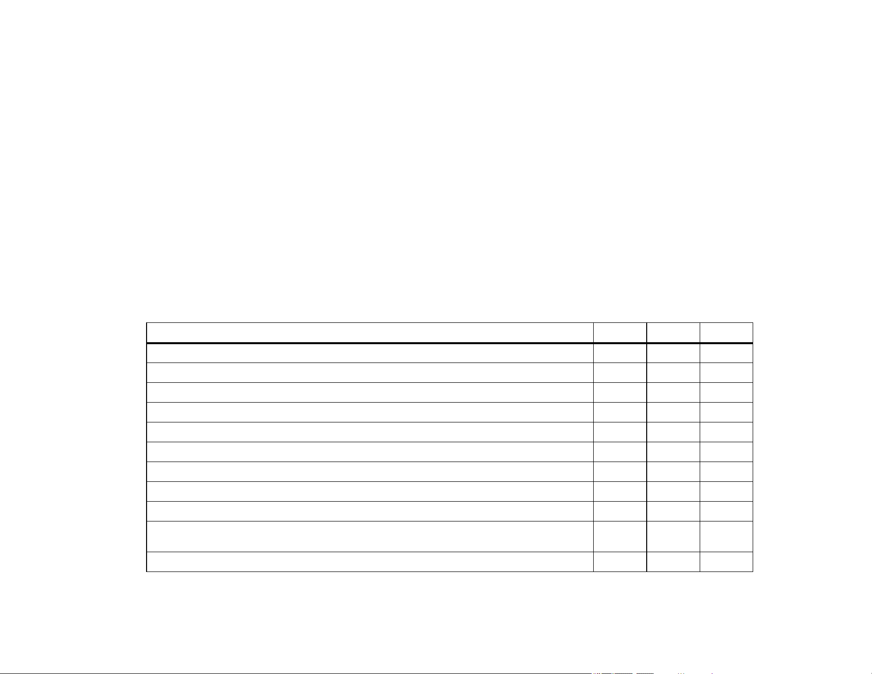
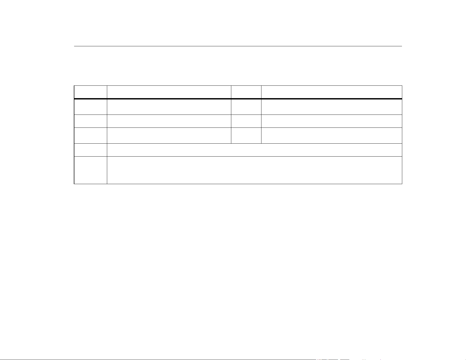
Table 1 is a list of features available by model number.
Table 1. Model Features
Feature 709 709H 710
Current measurement, sourcing, and a selectable 24 V supply
•••
30 V dc measurement
•••
Valve test capability
•••
Output step and ramp
•••
Large backlight display
•••
Digital selection knob with selectable decade control for easy data entry
•••
Interactive menus
•••
Selectable English or German user interface
••
A selectable HART 250 Ω loop resistor
••
Communicator mode reads basic device information, does diagnostic tests, and can be used to trim
the 4-20 mA output of most HART-enabled transmitters.
••
Supports test functions for HART smart control valves
•
1.888.610.7664 sales@GlobalTestSupply.com
Fluke-Direct.com

709/709H/710
Users Manual
2
Safety Information
A Warning identifies hazardous conditions and procedures that
are dangerous to the user. A Caution identifies conditions and
procedures that can cause damage to the Product or the
equipment under test.
XW Warning
To prevent possible electrical shock, fire, or
personal injury:
• Read all safety Information before you use the
Product.
• Use the Product only as specified, or the
protection supplied by the Product can be
compromised.
• Examine the case before you use the Product.
Look for cracks or missing plastic. Carefully
look at the insulation around the terminals.
• Do not use test leads if they are damaged.
Examine the test leads for damaged insulation
and measure a known voltage.
• Do not use and disable the Product if it is
damaged.
• Do not use the Product around explosive gas,
vapor, or in damp or wet environments.
• Do not touch voltages >30 V ac rms, 42 V ac
peak, or 60 V dc.
• Do not apply more than the rated voltage,
between the terminals or between each terminal
and earth ground.
• Do not connect directly to mains.
• Do not exceed the Measurement Category (CAT)
rating of the lowest rated individual component
of a Product, probe, or accessory.
• Keep fingers behind the finger guards on the
probes.
• Remove all probes, test leads, and accessories
before the battery door is opened.
• Remove the batteries if the Product is not used
for an extended period of time, or if stored in
temperatures above 50 °C. If the batteries are
not removed, battery leakage can damage the
Product.
• Replace the batteries when the low battery
indicator shows to prevent incorrect
measurements.
• The battery door must be closed and locked
before you operate the Product.
1.888.610.7664 sales@GlobalTestSupply.com
Fluke-Direct.com
Precision Loop Calibrator
Symbols
3
Symbols
Table 2 is a list of symbols used on the Product or in this manual.
Table 2. Symbols
Symbol Description Symbol Description
W
WARNING - RISK OF DANGER. Consult user
documentation.
Conforms to relevant South Korean EMC Standards.
Earth
Conforms to relevant Australian EMC standards.
Battery
)
Certified by CSA Group to North American safety
standards.
P
Conforms to European Union directives.
~
This product complies with the WEEE Directive marking requirements. The affixed label indicates that you must not
discard this electrical/electronic product in domestic household waste. Product Category: With reference to the equipment
types in the WEEE Directive Annex I, this product is classed as category 9 "Monitoring and Control Instrumentation"
product. Do not dispose of this product as unsorted municipal waste.
1.888.610.7664 sales@GlobalTestSupply.com
Fluke-Direct.com
709/709H/710
Users Manual
4
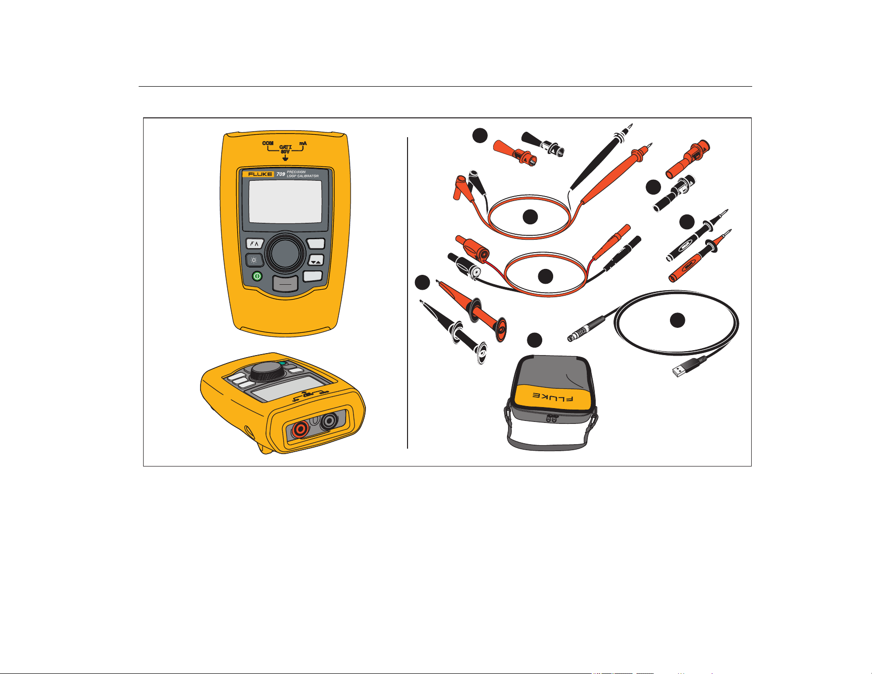
Standard Equipment
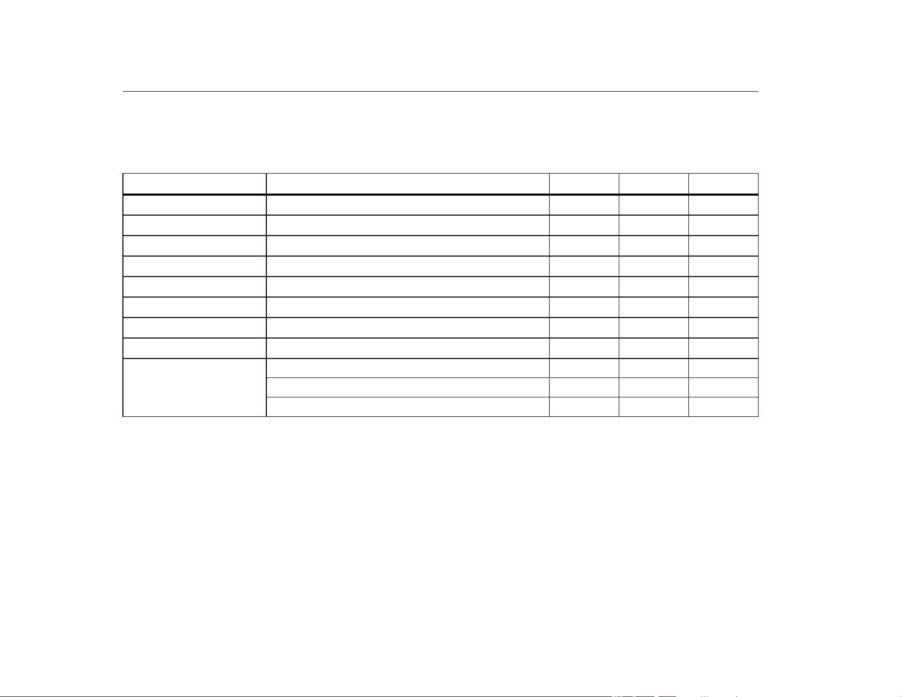
Table 3 is a list of items included with the Product. See Figure 1 for
details.
Table 3. Standard Equipment
Item Description 709 709H 710
Two AC72-1 alligator clips
•
TL-75-4201 test leads
•
754-8016 alligator clip set
••
75X-8014 stackable lead set
••
TP220-4201 test probes
••
AC280-5001 Suregrip hook clips
••
USB to 5-pin Lemo Cable, 6-ft (1.8 m)
•
Soft Case
•••
Not Shown
Six IEC LR03 batteries (installed)
•••
Quick Reference Guide
•••
Safety Information
•••
1.888.610.7664 sales@GlobalTestSupply.com
Fluke-Direct.com
Precision Loop Calibrator
Standard Equipment
5
Figure 1. Standard Equipment
25%
MENU
EXIT
0%
100%
1
2
3
4
5
6
7
8
1.888.610.7664 sales@GlobalTestSupply.com
Fluke-Direct.com
709/709H/710
Users Manual
6
The Product
The subsequent sections are about the features and functions of
the Product.
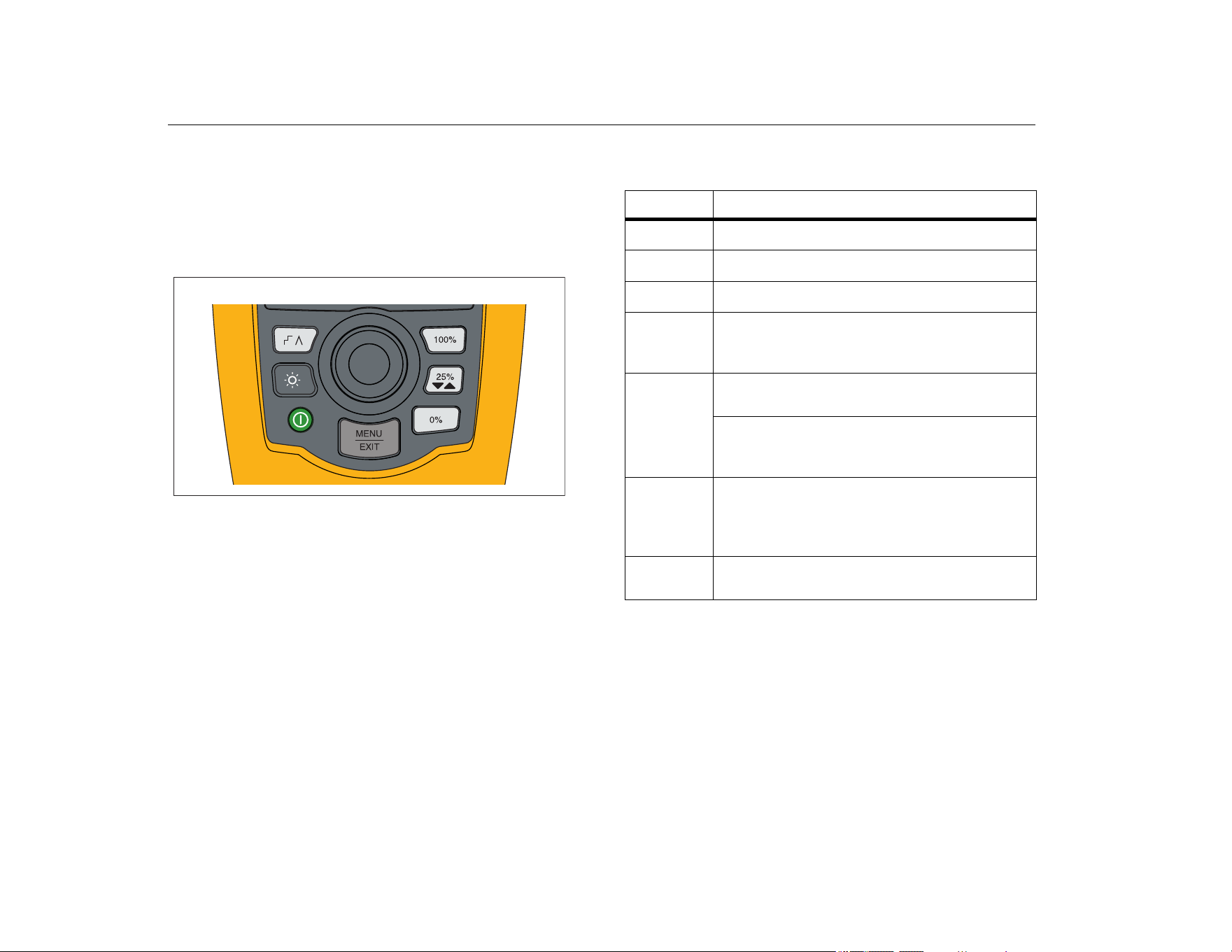
The Buttons
Figure 2 and Table 4 show the location and brief descriptions of
the Product buttons.
Figure 2. Button Locations
Table 4. Button Descriptions
Button Function
Push to enable step, ramp, or start valve tests.
Push to turn on or turn off the backlight.
Push to turn on and turn off the Product.
Push to set the output to 20 mA when in mA
Source or mA Simulate modes. In Measurement
mode the button does not set the output current.
Push to step the output up or down by 25 %
increments (4, 8, 12, 16, 20 mA).
When valve test is enabled, push to step the
output as 3.8, 4, 4.2, 8, 12, 16, 19.8, 20, and
20.2 mA.
Push to set the output to 4 mA when in mA
Source or mA Simulate mode.
In Measurement mode the button does not set the
output current.
Push to enter the Main menu. Push a second time
to exit the Main menu. See Main Menu.
1.888.610.7664 sales@GlobalTestSupply.com
Fluke-Direct.com
Precision Loop Calibrator
Main Menu
7
The Selection Knob
The selection knob lets you select and control functions and
navigate through the Product menus. Turn the selection knob to
highlight a menu item or adjust a value. When the item is
highlighted, push the selection knob to do the selected action, or
push and hold to save any changes that have been made. Push
to go to the main screen with no action.
In the output modes (mA Source, mA Simulate):
• Push the selection knob to move the display cursor to the next
digit.
• Turn the selection knob to increment or decrement the output
in steps shown by the selected decade.
• Push
, , or to set the output to preset values.
• Push to select and stop these advanced modes.
Language Selection
For the 709/709H models, the user interface language is available
in English or German.
To change:
1. Turn off the Product.
2. Simultaneously push and hold
and as you turn on
the Product.
3. At the prompt, use the selection knob to highlight the
language choice.
4. Push the selection knob to accept the choice.
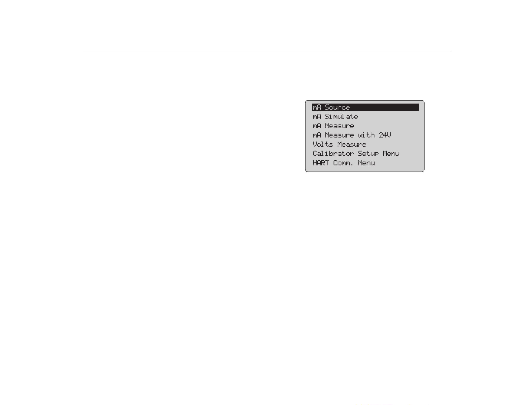
Main Menu
Push to show the Main menu, choose the primary operation
mode of the Product, access the Product setup menu, or to use
HART mode. See Figure 3.
Figure 3. Main Menu
The first five items that show on the Main menu change the
Product operation mode accordingly and once selected, change
the Product menu to a Home screen for the selected function. The
operation modes are explained in the subsequent sections of this
manual.
For the last two items of the Main menu, see Calibrator Setup
Menu and HART Comm. Menu.
Note
The HART menu items only apply to the 709H and
710.
Some menus have multiple screens. In this case, the
lower-left corner of the menu shows when additional
screens follow the current screen. shows when
additional screens precede the current screen. Both
icons show when additional screens follow and
precede the present screen.
1.888.610.7664 sales@GlobalTestSupply.com
Fluke-Direct.com
709/709H/710
Users Manual
8
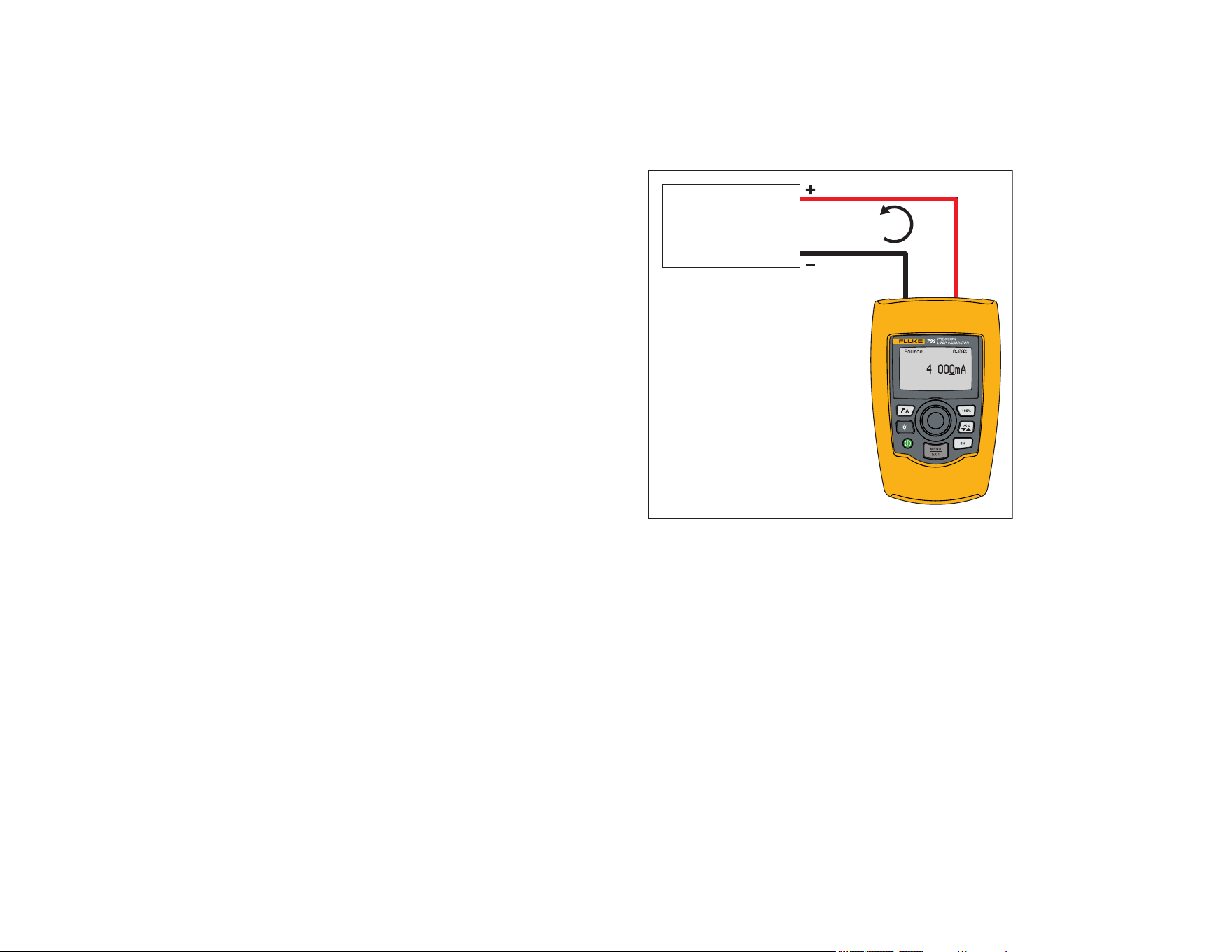
mA Source
In the mA Source mode, the Product outputs a signal from 0 mA
to 24 mA into a load of up to 1200 Ω (950 Ω if the internal HART
resistor is switched on).
Figure 4 shows the mA Source home screen and typical
connections for this mode.
To use mA Source:
1. Select mA Source from the Main menu.
2. Push the selection knob to move the decade cursor.
3. Turn the selection knob to increment or decrement the output
in steps indicated by the selected decade.
4. Push
, , or to set the output to preset values.
5. Push to select and stop these advanced modes. When
automatic step or ramp is active, one of the subsequent icons
show in the lower left corner:
Automatic step:
Automatic ramp:
6. Push
to go to the Main menu.
7. Push again to go to the mA Source home screen.
• Valve Test shows in the lower center when the valve test
function has been enabled on the Setup menu. See the
Valve Test.
• 250Ω shows in the lower right corner when the HART
resistor has been enabled on the setup menu.
Figure 4. mA Source Connections
4 mA to 20 mA
4 mA to 20 mA
Input Device,
Recorder/Indicator,
etc.
4 mA to 20 mA
Input Device.
Recorder/Indicator,
etc.
4 mA to 20 mA
1.888.610.7664 sales@GlobalTestSupply.com
Fluke-Direct.com
Precision Loop Calibrator
Main Menu
9
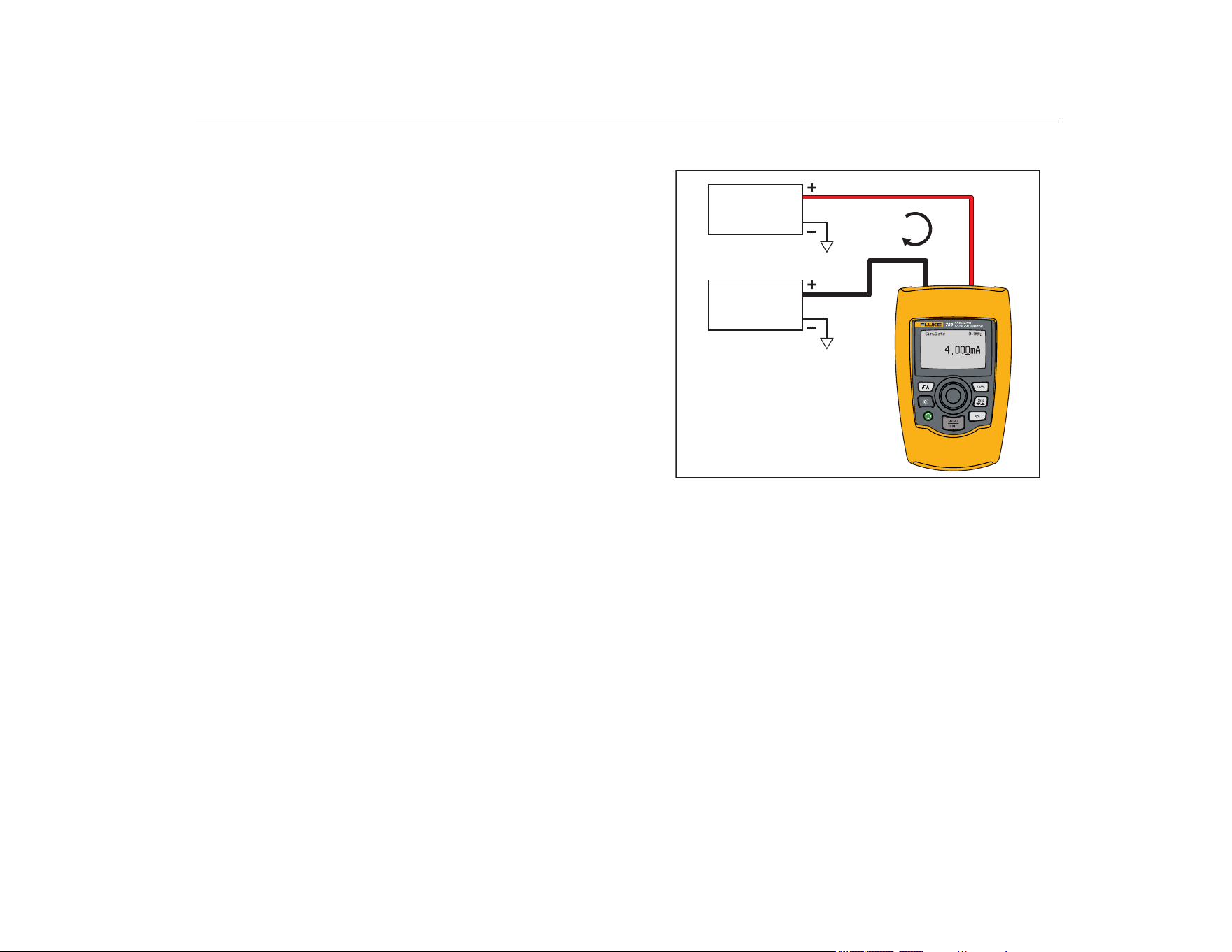
mA Simulate
In the mA Simulate mode, the Product functions like a 2-wire
transmitter and controls the loop current from an external power
supply. This function can test a loop with the transmitter removed.
Figure 5 shows the mA Simulate home screen and typical
connections for this mode.
To use mA Simulate:
1. Select mA Simulate from the Main menu.
2. Push the selection knob to move the decade cursor.
3. Turn the selection knob to increment or decrement the output
in steps indicated by the selected decade.
4. Push
, , or to set the output to preset values.
5. Push to select and stop these advanced modes. When
automatic step or ramp is active, one of the subsequent icons
shows in the lower left corner:
• Automatic step:
• Automatic ramp:
6. Push
to go to the Main menu.
7. Push again to go to the mA Simulate home screen.
• Valve Test shows in the lower center when the valve test
function has been enabled on the Setup menu. See the
Valve Test.
• 250Ω shows in the lower right corner when the HART
resistor has been enabled on the setup menu.
Figure 5. mA Simulate Connections
4 mA to 20 mA
Power Supply
30 V dc Max
4 mA-20 mA
Input Device
4 mA to 20 mA
4 mA to 20 mA
Input Device
Power Supply
30 V dc Max
1.888.610.7664 sales@GlobalTestSupply.com
Fluke-Direct.com

709/709H/710
Users Manual
10
mA Measure
In the mA Measure mode, the Product shows the loop current
measurement. This mode is without 24 V.
Figure 6 shows the mA Measure home screen and typical
connections for this mode.
To use mA Measure, select mA Measure from the Main menu.
When selected, the Product changes to the mA Measure home
screen.
250Ω shows in the lower right corner when the HART resistor is
enabled on the setup menu.
Figure 6. mA Measure Connections
4 mA to 20 mA
4 mA-20 mA
Output Device
4 mA to 20 mA
Output Device
4 mA to 20 mA
1.888.610.7664 sales@GlobalTestSupply.com
Fluke-Direct.com
Precision Loop Calibrator
Main Menu
11
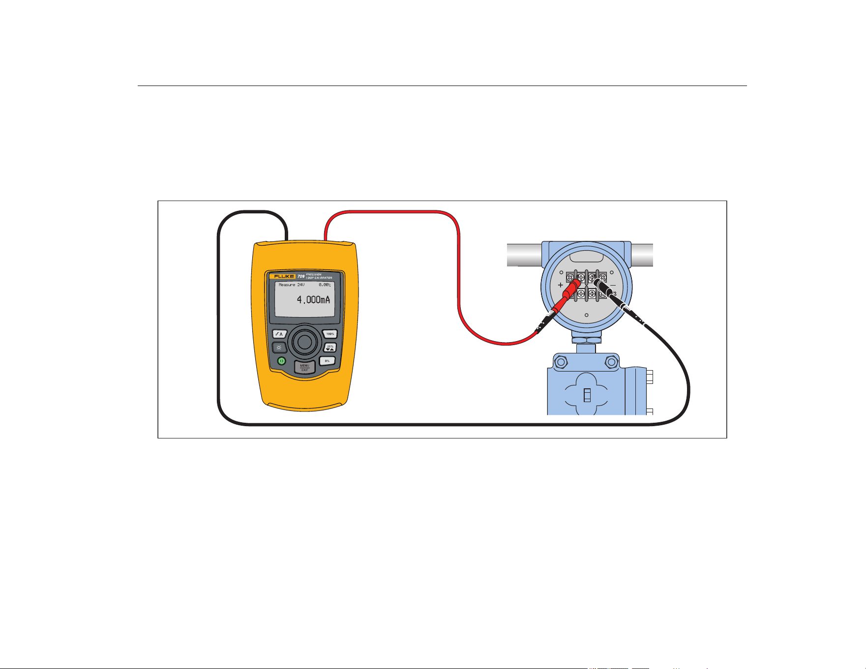
mA Measure with 24V
In the mA Measure with 24V mode, the Product outputs 24 V dc
as it shows the loop current. This mode powers a transmitter
without a separate power supply.
Figure 7 shows the home screen and typical connections for this
mode.
To use mA Measure with 24V, select mA Measure with 24V from
the Main menu. When selected, the Product changes to the mA
Measure with 24V home screen. 250Ω shows in the lower right
corner when the HART resistor is enabled on the setup menu.
Figure 7. mA Measure with 24 V Connections
1.888.610.7664 sales@GlobalTestSupply.com
Fluke-Direct.com
709/709H/710
Users Manual
12
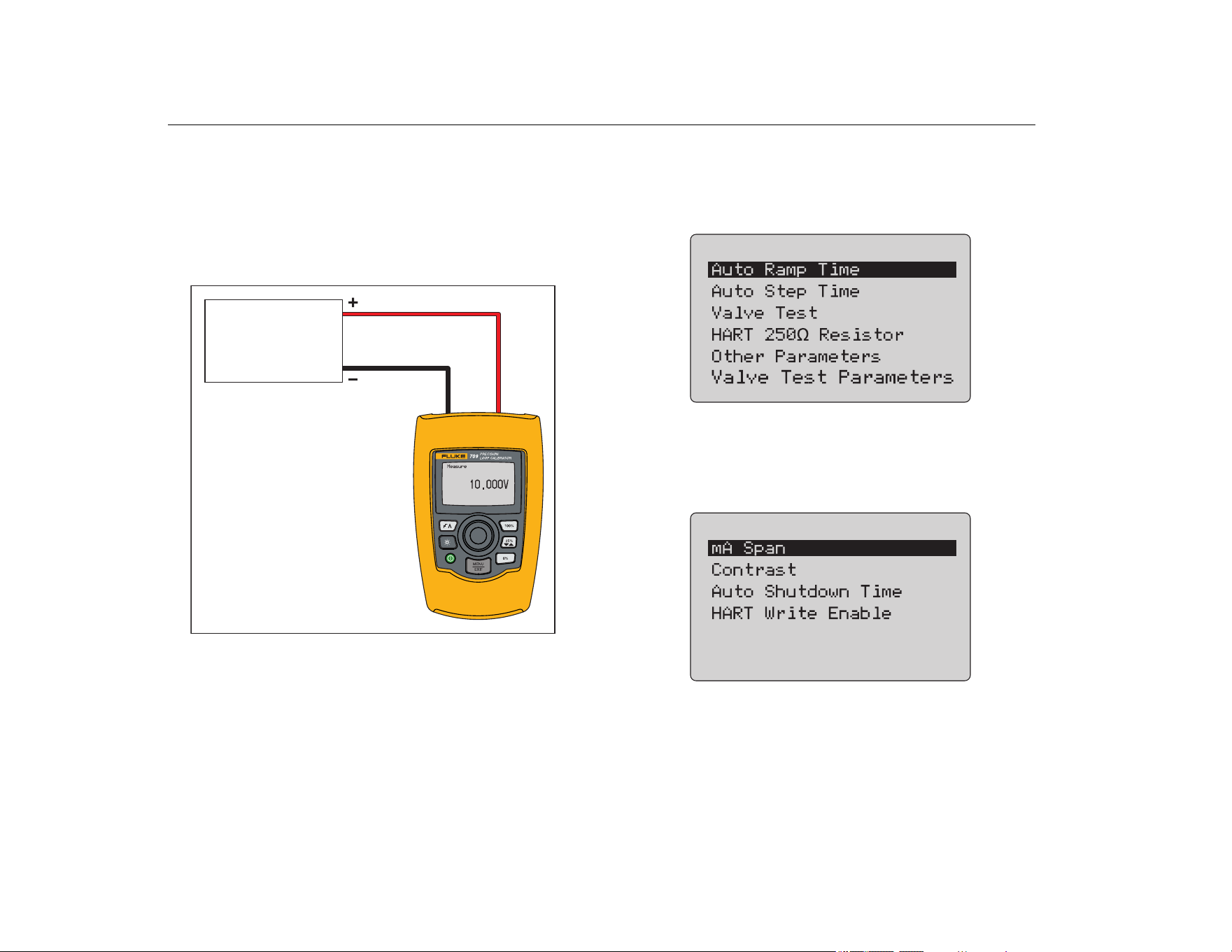
Volts Measure
In the Volts Measure mode, the Product shows the loop voltage.
Figure 8 shows the Volts Measure home screen and typical
connections for this mode.
To use the Volts Measure mode, select Volts Measure from the
Main menu. When selected, the Product changes to the Volts
Measure home screen.
Figure 8. Volts Measure Connections
Calibrator Setup Menu
The Calibrator Setup Menu has two screens. To go to the second
screen, select Other Parameters from the first screen. Screen 1
shows in Figure 9 and screen 2 shows in Figure 10.
Figure 9. Setup Menu, Screen 1
Note
The Valve Test Parameters menu item only shows on
the 710.
Figure 10. Other Parameters Menu, Screen 2
Note
The HART Write Enable menu item only shows on the
709H and 710.
Voltage
Output Device
Voltage Output
Device
1.888.610.7664 sales@GlobalTestSupply.com
Fluke-Direct.com
Precision Loop Calibrator
Calibrator Setup Menu
13
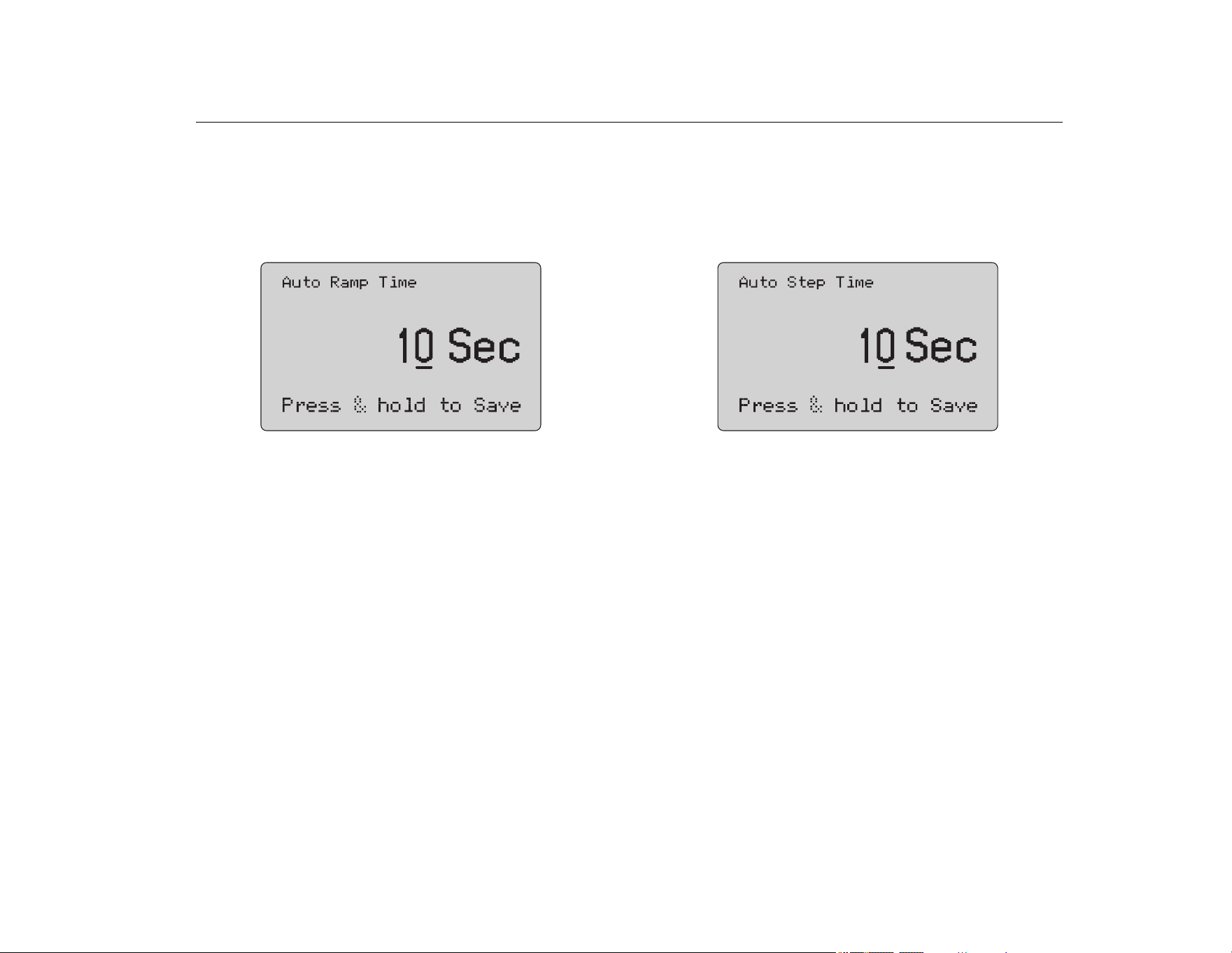
Auto Ramp Time
The Auto Ramp Time function sets the full-scale ramp time for the
mA ramp feature. The value can be set from 5 seconds to
300 seconds. Push the selection knob to move the decade cursor.
Turn the selection knob to adjust the value in steps indicated by
the decade selected. See Figure 11.
Figure 11. Auto Ramp Time Screen
Note
The ramp time setting also changes the ramp time for
the valve tests.
Auto Step Time
The Auto Step Time function sets the step interval time for the mA
Auto Step feature. The value can be set from 5 seconds to
300 seconds. Push the selection knob to move the decade cursor.
Turn the selection knob to adjust the value in steps indicated by
the decade selected. See Figure 12.
Figure 12. Auto Step Time Screen
Step and Ramp Operation
For step and ramp operation, the percent keys can be used to set
the milliamp output to 0 % of span, 100 % of span, or step the
output by 25 % of span.
Hands-free operation is possible with . Set the Product to
automatically and continuously step or ramp the milliamp output
from 0 % to 100 % and back.
The 100 % value is always 20 mA, but the 0 % value can be 0 mA
or 4 mA. This depends on how the mA span is set. The 25 % step
size is 5 mA or 4 mA accordingly.
To use the manual step function:
1. Use the Main menu to set the Product to source or simulate
current.
2. Push to set the output to 0 % of span.
3. Push to set the output to 100 % of span.
4. Push to step the output in 25 % of span increments, from
0 % of span to 100 % of span and back.
1.888.610.7664 sales@GlobalTestSupply.com
Fluke-Direct.com
709/709H/710
Users Manual
14
Automatic Step and Ramp
To use the automatic step and automatic ramp functions:
1. Use the Main menu to set the Product to source or simulate
current.
2. The Product has separate auto ramp and step times. Use the
menu to set the ramp or step time.
3. Push once to continually step the output from 0 % of span
to 100 % of span and back in increments of 25 % of span at
the specified interval.
4. Push once more to go to auto ramp.
5. Push one of the percent keys, and twice, to turn off the
auto step and ramp.
6. Push twice to continually ramp the output from 0 % of
span to 100 % of span over the specified interval, and then
back over the specified interval.
7. Push one of the percent keys or once more, to turn off the
auto step and ramp.
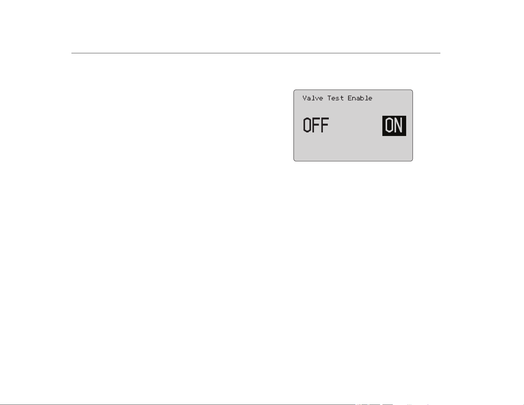
Valve Test
The Valve Test function turns on or off the valve test feature. See
Figure 13.
Figure 13. Valve Test Enable Screen
The valve test verifies correct operation of valves. In valve test, the
output can be stepped to these values:
• 3.8 mA
• 4.0 mA
• 4.2 mA
• 8.0 mA
• 12.0 mA
• 16.0 mA
• 19.8 mA
• 20.0 mA
• 20.2 mA
The valve test mA values are not affected by the mA span setting.
1. Use the Main menu to set the Product to source or simulate
current.
2. If valve test is not enabled, use the menu to enable it.
3. Push or to step the output to verify the proper valve
operation.
4. Use the menu to disable valve test when done.
1.888.610.7664 sales@GlobalTestSupply.com
Fluke-Direct.com
Precision Loop Calibrator
Calibrator Setup Menu
15
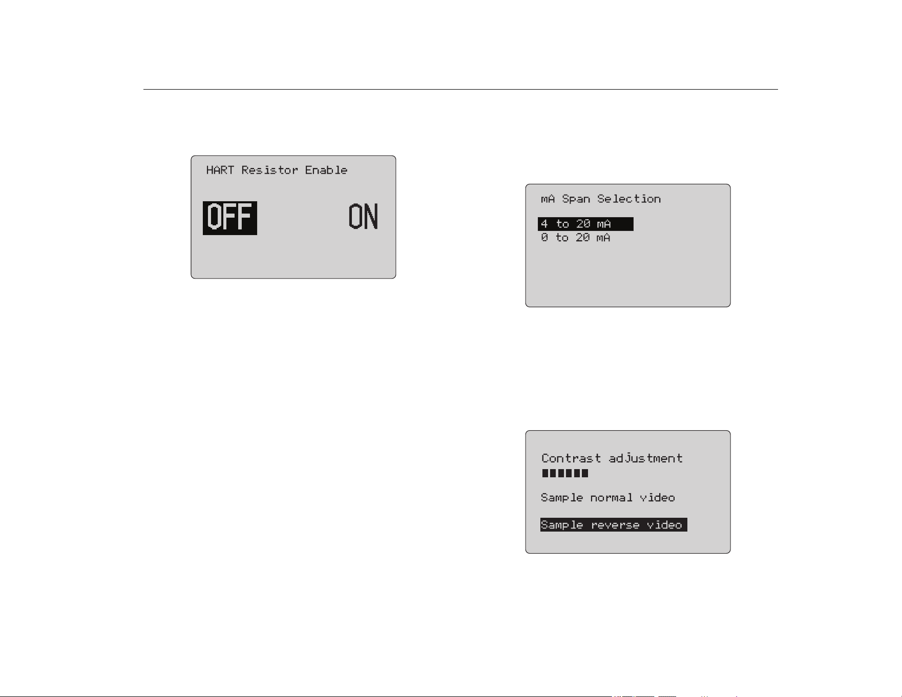
HART 250Ω Resistor
The HART 250Ω Resistor Enable function turns on and turns off
the HART resistor. See the HART Resistor. See Figure 14.
Figure 14. HART Resistor Enable Screen
The Product can insert a 250 Ω resistor in series with the power
supply in order to use a HART communicator. The HART resistor
is enabled through the menu.
To get to the second Calibrator Setup Screen, highlight Other
Parameters and push the selection knob.
Valve Test Parameters
Use the Valve Test Parameters menu to set the 710 parameters
to match the valve parameters (for example, PV, SV, TV, and QV).
This menu also sets the default test tolerances for all test
templates.
mA Span
mA Span is the first item on the second Calibrator Setup Menu.
The mA Span function sets the step interval for the mA Auto Step
feature. The value can be set from 5 seconds to 300 seconds. See
Step and Ramp Operation. See Figure 15.
Figure 15. mA Span Selection Screen
Contrast
The Contrast function adjusts the display contrast. Turn the
selection knob to adjust the contrast. The range shows by the bar
graph. Higher contrast shows by a longer bar. The sample normal
and reverse video selections let you evaluate both text modes.
See Figure 16.
Figure 16. Contrast Adjustment Screen
1.888.610.7664 sales@GlobalTestSupply.com
Fluke-Direct.com
709/709H/710
Users Manual
16
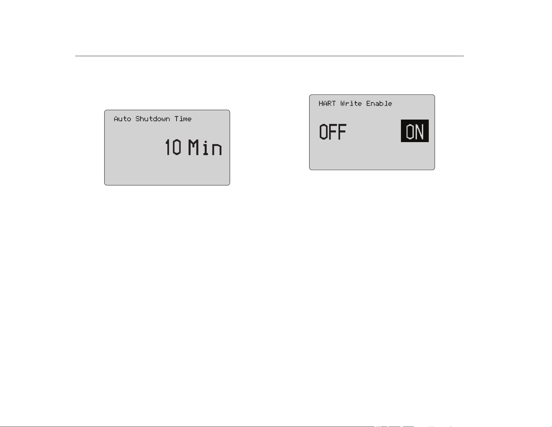
Auto Shutdown Time
The Auto Shutdown Time function sets or turns off the time
before the Product automatically shuts itself down if the keypad is
not used. The value can be set to Disabled, or from 1 minute to
30 minutes. See Figure 17.
Figure 17. Auto Shutdown Screen
HART Write Enable
HART Write Enable is the last function in the Calibrator Setup
Menu. See Figure 18.
Figure 18. Hart Write Enable Screen
This function is available only on the 709H and 710. It protects the
Write LRV, Write URV, Device Diagnostic, Trim 4mA, Trim 20mA,
Set Fixed Output, and PV Zero functions. The default setting is
ON, but it may be turned off to protect the Product against
unauthorized use.
1.888.610.7664 sales@GlobalTestSupply.com
Fluke-Direct.com
Precision Loop Calibrator
HART Device Communication
17
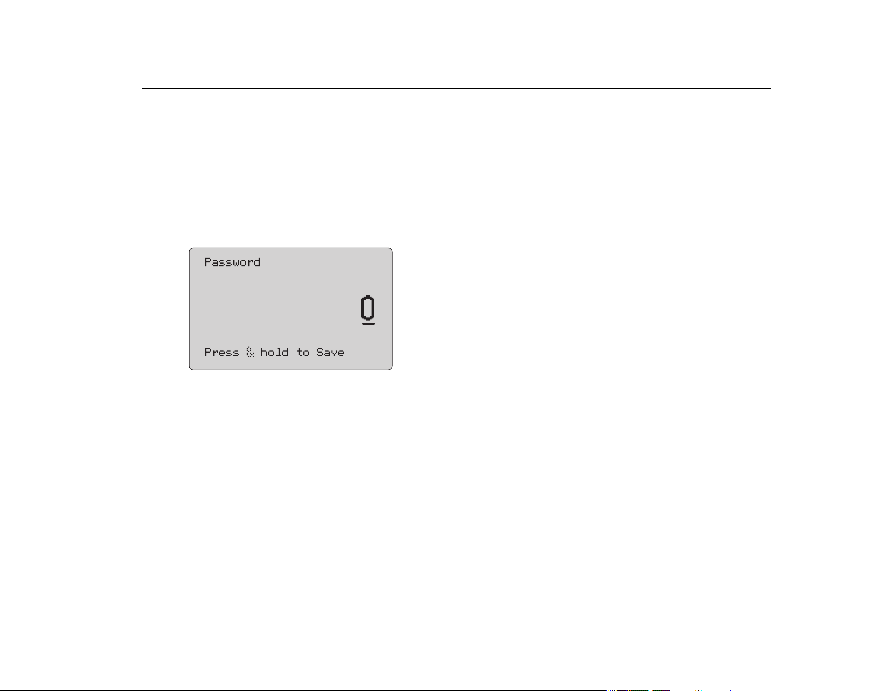
Before the setting is changed, a password is required. The
password is set to 617 at the factory. The range of values that can
be set is 000 to 999. See Figure 19.
The write-enable selection is saved only when the correct
password is given. Otherwise an error message shows.
Push the selection knob to move the decade cursor. Turn the
selection knob to adjust the value in steps indicated by the decade
selected. Push and hold the selection knob to save the write
enable setting. Push
to restore the previous HART-enable
selection and go to the Main screen.
Figure 19. Password Screen
HART Device Communication
The HART functions are only available in the 709H and 710.
Auto shutdown is disabled when the HART menus are used. Auto
shutdown is restored to its previous state when you exit the HART
menus.
Note
Loop current trim is supported for transmitter devices,
but is not supported for actuator devices.
These functions can be disabled with the HART Write Enable
selection on the Product:
• write LRV
• write URV
• write PV unit
• device diagnostic
• auto trim (710 only)
• trim 4 mA
• trim 20 mA
• set fixed mA output
• PV zero
• modify Tags, Msg, Description
The 710 uses additional HART commands to execute the
Signature, Step, Speed, and Bump/Partial Stroke tests.
PV zero functions can be disabled with the HART Write Enable
selection on the Calibrator Setup menu. See Calibrator Setup
Menu. If these functions are required, they must be enabled before
you enter the HART menus.
1.888.610.7664 sales@GlobalTestSupply.com
Fluke-Direct.com
709/709H/710
Users Manual
18
HART Connections
See the subsequent sections for HART connections.
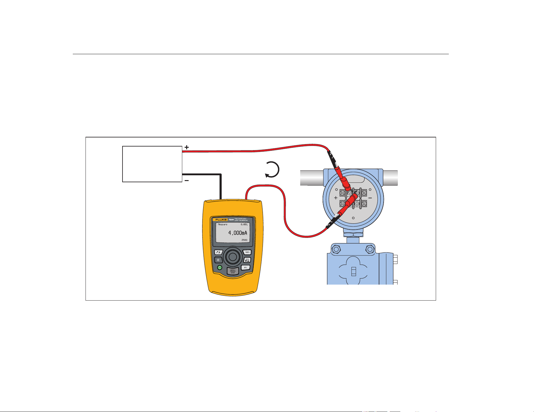
In Circuit, External Loop Power
In mA Measure mode, the Product is in circuit and loop power is
supplied externally. In Figure 20, the 250 HART resistor is
enabled. If the loop already has 250 Ω, do not enable the HART
resistor.
Figure 20. In Circuit, External Loop Power Connections
4 mA to 20 mA
24 V
Supply
4 mA to 20 mA
24 V
Supply
1.888.610.7664 sales@GlobalTestSupply.com
Fluke-Direct.com
Precision Loop Calibrator
HART Device Communication
19
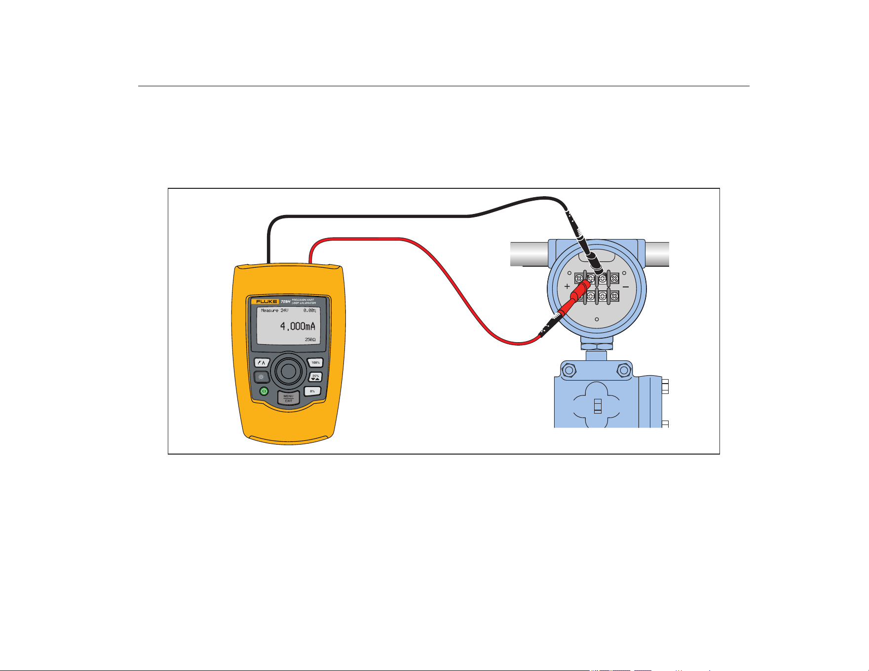
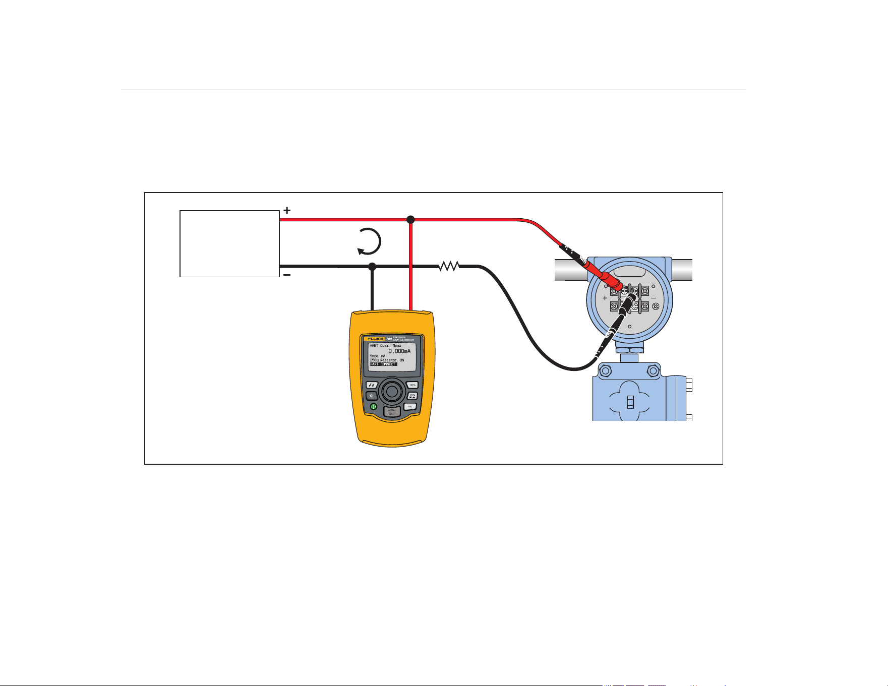
In Circuit, Product Loop Power
In mA Measure with 24V mode, the Product is in circuit and loop
power is supplied by the Product. In Figure 21, the 250 Ω HART
resistor is enabled. If the loop already has 250 Ω, do not enable
the HART resistor.
Figure 21. In Circuit, 709H Loop Power
1.888.610.7664 sales@GlobalTestSupply.com
Fluke-Direct.com
709/709H/710
Users Manual
20
Across Circuit, Communicator Only
In Communicator Only mode, the Product is across the circuit
and loop power is supplied externally. In Figure 22, when in
Communicator Only mode, there must be 250 Ω resistance
present in the loop.
Figure 22. Across Circuit, Communicator Only Connections
4 mA to 20 mA
RL ≥ 250 Ω
24 V
Supply
24 V
Supply
4 mA to 20 mA
RL ≥25 Ω
1.888.610.7664 sales@GlobalTestSupply.com
Fluke-Direct.com
Precision Loop Calibrator
HART Device Communication
21
Communications Setup and Selection
For all Main screen operation modes, except mA Measure with
24V or Volts Measure, the operation mode is set to mA Measure
when you enter the HART Comm. Menu.
The operation mode remains the same as the main screen when it
is Measure with 24V. If Volts Measure was selected from the
Main menu, the menu defaults to communicator mode only and
the 250 Ω resistor selection shows n/a.
The 250 Ω resistor selection cannot be edited in communicator
mode.
The mode and resistor will change from the last selections made in
the HART Comm. Menu when you exit the menu.
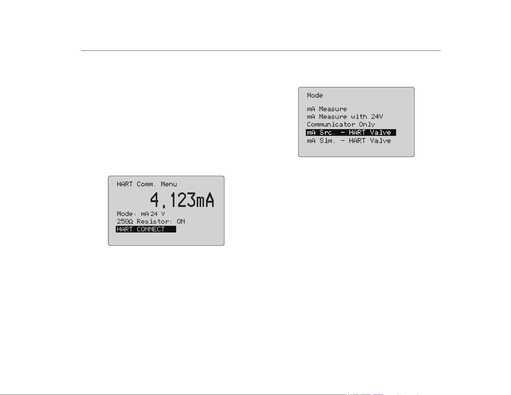
The mode and 250 Ω resistor settings must correspond to how the
test leads are connected before you connect. See Figure 23.
Figure 23. HART Comm. Menu Screen
Select a function from the menu and push the selection knob to do
the function. Push
to disconnect from HART mode and go to
the function home screen without action.
An error shows and no action is taken if the measured input is out
of range, OL or -OL.
250Ω Resistor and HART CONNECT functions are described in
subsequent sections.
Mode
The Mode function from the HART. Comm. Menu lets you select
what mode to work in. See Figure 24.
Figure 24. Mode Selection Screen
Use the selection knob to choose the mode:
• mA Measure- The Product is in circuit and loop power is
supplied externally.
• mA Measure with 24V- The Product is in circuit and the loop
power is supplied by the Product.
• Communicator Only- The Product is across the circuit and
the loop power is supplied externally. The 250 Ω resistor
selection defaults to n/a (not applicable).
• mA Src HART Valve- to source mA signals and communicate
HART to connect and communicate with control valves.
• mA Sim HART Valve- to simulate mA signals and
communicate HART to connect and communicate with control
valves with control system 24 V loop power.
1.888.610.7664 sales@GlobalTestSupply.com
Fluke-Direct.com
709/709H/710
Users Manual
22
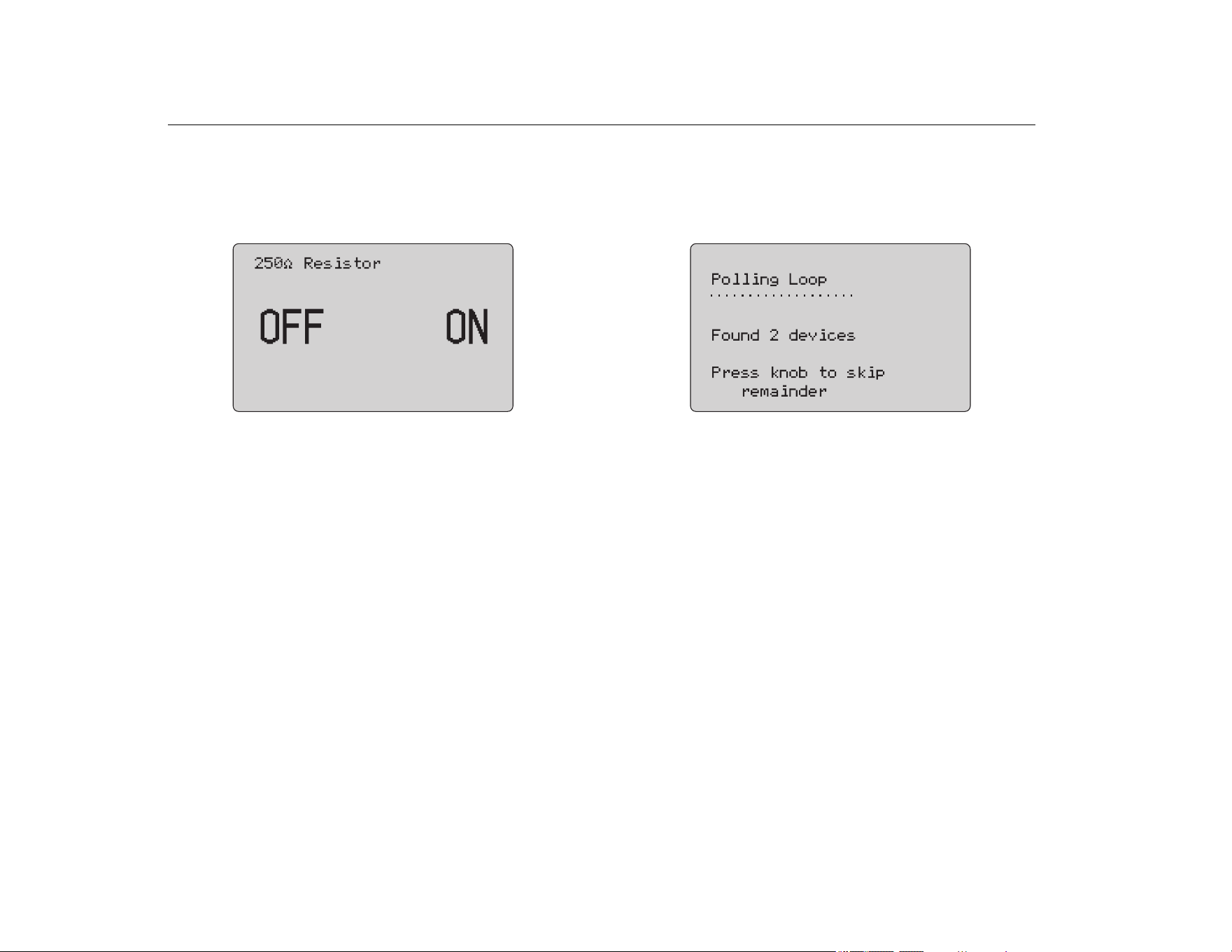
250Ω Resistor
The 250Ω Resistor function lets you turn the 250 Ω resistor on or
off. Use the selection knob to change the resistor to the highlighted
selection and return to the Setup and Selection screen. See
Figure 25.
Figure 25. 250Ω Resistor Screen
HART Connect
The HART Connect function locates the HART device in the loop.
Before an operation with a HART device, the device must be
located on the loop. This is done by polling all of the possible
device addresses and selecting a device from those addresses
that respond to the search.
If a HART protocol revision 5 or earlier device is found on the loop,
polling stops at poll address 15. If not found, the Product continues
to poll address 63. Polling stops after 10 devices are found on the
loop.
If multiple devices are found on the loop, a tag list shows. From the
list, select the correct device. If only one device is found on the
loop, it becomes the selected device by default.
When a selected device is found, all relevant data is read from the
device and the operations described in the Function Select Menu
and Device Setup and Data sections of this manual become
available.
Polling Loop
The Polling Loop function searches the loop for HART devices.
This function starts immediately. The screen changes to show the
string of dots that is extended once per second to as the operation
progresses. See Figure 26.
Figure 26. Polling Screen
The number of devices found on the loop during polling shows.
The selection knob can be pushed to stop polling early if it is
known that all of the devices on the loop have been found. Push
to stop polling, disconnect from HART mode, and go to the
function home screen.
An error shows if no device is found.
If multiple devices are found, a list of tags shows. Use the list of
tags to select the device.
If only one device is found, the tag selection step is skipped.
1.888.610.7664 sales@GlobalTestSupply.com
Fluke-Direct.com
Precision Loop Calibrator
HART Device Communication
23
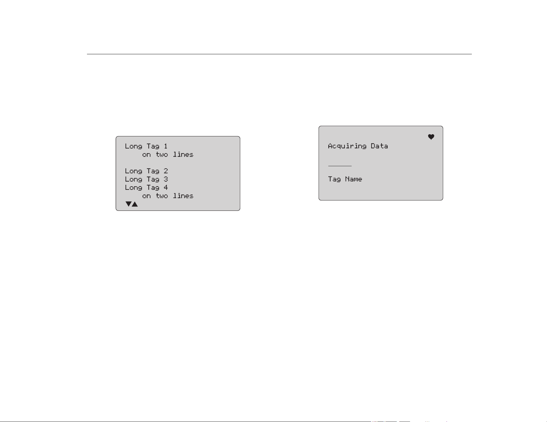
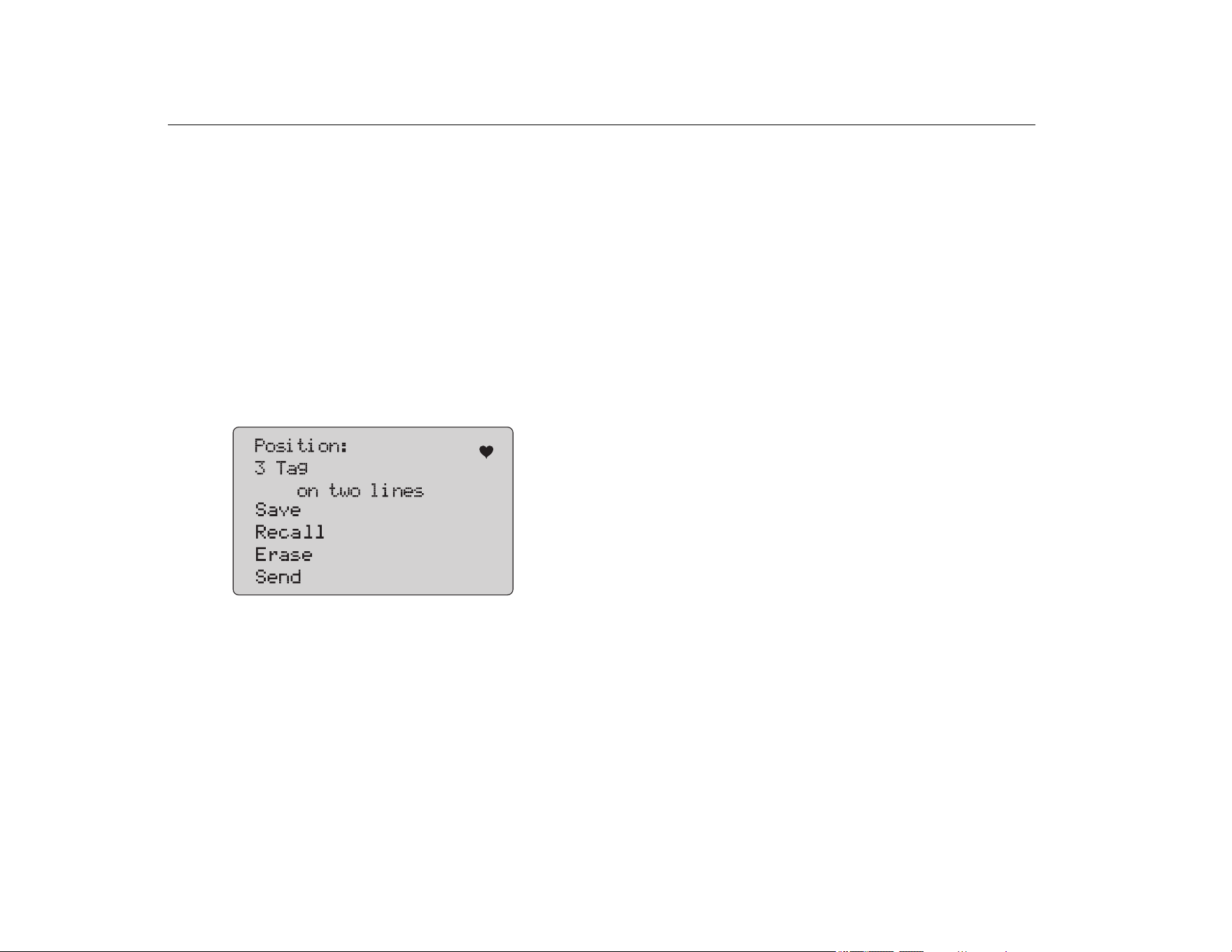
Tag Selection
The tag selection screen lists all of the long tag names found
during polling. Tag names can span two lines if to show all of the
text.
If the long tag name is not available, or it is blank, a short tag name
is used. If the short tag name is blank, the text Poll address x is
used.
Use the selection knob to go to the tag. See Figure 27.
Figure 27. Tag Selection Screen
Acquiring Data
The Acquiring Data screen shows while the Product acquires all
of the configuration data from the device. The string of dots
extends once per second to show the operation progress.
flashes in the upper-right corner to show a live HART connection.
The screen in Figure 28 shows the name of the tag that is
accessed.
Figure 28. Acquiring Data Screen
Push
to stop data acquisition, disconnect from HART mode,
and go to the function home screen.
When data acquisition is complete, the Function Select Menu
shows.
1.888.610.7664 sales@GlobalTestSupply.com
Fluke-Direct.com
709/709H/710
Users Manual
24
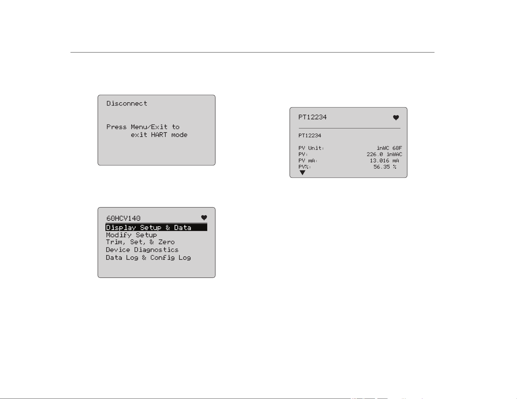
Disconnect from Loop
The Disconnect from Loop screen shows before the Product
returns to the function home screen so the Product can be
disconnected from the Loop. See Figure 29.
Figure 29. Disconnect from Loop Screen
Function Select Menu
The Function Select menu shows in Figure 30.
Figure 30. Function Select Menu
The tag name is truncated if too long to fit on one. flashes in the
upper-right corner to show a live connection.
Use the selection knob to choose the action. Push
to
disconnect from HART mode and go to the function main screen.
Display Setup and Data
The Display Setup and Data screen spans 11 screens with the
format shown in Figure 31.
Figure 31. Sample Screen
This screen shows all of the data retrieved from the data
acquisition procedure.
The tag name is truncated if too long to fit on one line. flashes in
the upper-right corner to show a live connection.
Each screen holds a maximum of 6 data points. An item can span
more than one line to show the full text. If a data item is not
supported in the HART device, it is marked n/a (not available).
Data items that change dynamically in the HART device are
updated as often as possible on the screens.
Turn the selection knob to go from screen to screen. Push
to
go to the Function Select menu.
1.888.610.7664 sales@GlobalTestSupply.com
Fluke-Direct.com
Precision Loop Calibrator
Write LRV and URV Values
25
Write LRV and URV Values
Note
For the screens in this section, tag names can be
truncated to fit on one line. flashes in the upper-
right corner to show a live connection.
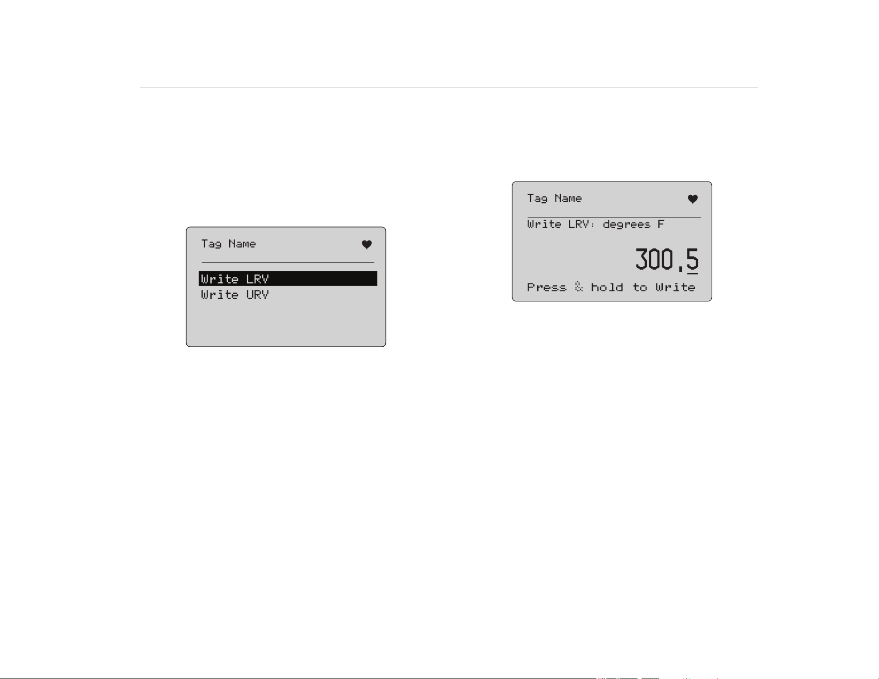
If the HART write commands are not active, these functions are
not available and an error message shows instead of the screen in
Figure 32.
Figure 32. Write LRV and URV Screen
Use the selection knob to choose the function. Push the selection
knob to choose the highlighted action and go to the corresponding
screen. See Write LRV and Write URV. Push
to go to the
Function Select menu.
Write LRV
The Product warns you to change the loop to MANUAL before you
proceed. Push the selection knob to proceed. Push
to go to
the Write LRV and Write URV menu.
The present LRV value and units show. See Figure 33.
Figure 33. Write LRV Screen
1. Push the selection knob to move the decade cursor.
2. Turn the selection knob to increment or decrement the value
in steps indicated by the selected decade.
3. Push and hold the knob to send the new value to the HART
device. An error shows if the HART device rejects the value.
4. Push
to go to the Function Select menu. A reminder to
change the loop to AUTOMATIC shows first.
1.888.610.7664 sales@GlobalTestSupply.com
Fluke-Direct.com
709/709H/710
Users Manual
26
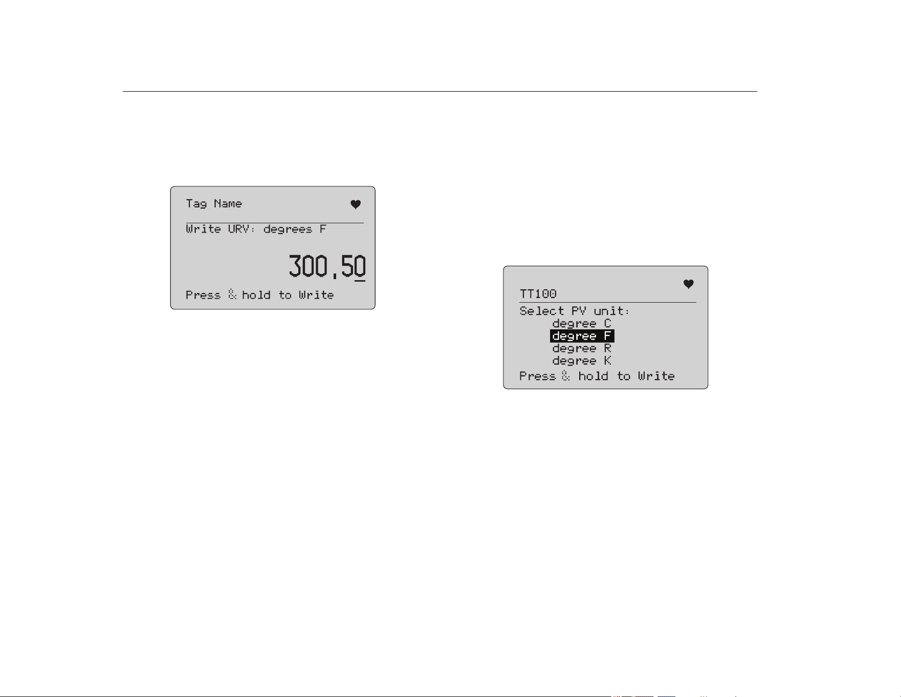
Write URV
The Product warns you to change the loop to MANUAL before you
proceed. Push the selection knob to proceed. Push
to go to
the LRV and URV menu.
The present URV value and units show. See Figure 34.
Figure 34. Write URV Screen
1. Push the selection knob to move the decade cursor.
2. Turn the selection knob to increment or decrement the value
in steps indicated by the selected decade.
3. Push and hold the knob to send the new value to the HART
device, remaining on this display. An error shows if the HART
device rejects the value.
4. Push
to go to the LRV and URV menu. A prompt to
change the loop to AUTOMATIC shows first.
Write PV Unit
The Product warns you to change the loop to MANUAL before you
proceed. Push the selection knob to proceed. Push
to go to
the Modify Setup menu.
The available units show with the present unit. For example, if the
present unit is PSI, a list of pressure units show. Another example
is if the present unit is °C, a list of temperature units show.
PV Units settings are limited to the common practice command
specification for HART protocol. Support for non-standard PV units
is limited if proprietary to a manufacturer that uses device-specific
commands. See Figure 35.
Figure 35. Write PV Unit Screen
The tag name is truncated if too long to fit on one line. The
symbol in the upper right corner flashes to show a working HART
connection.
To write a new value:
1. Rotate the selection knob to move the highlight
2. Push and hold the selection knob to send the new value to the
HART device.
The screen prompts you to change the loop to AUTOMATIC
and changes to the Modify Setup menu.
An error message shows if the HART device rejects the value
for any reason.
1.888.610.7664 sales@GlobalTestSupply.com
Fluke-Direct.com
Precision Loop Calibrator
Write LRV and URV Values
27
3. Push to return to the Modify Setup menu. The screen
prompts you to change the loop to AUTOMATIC.
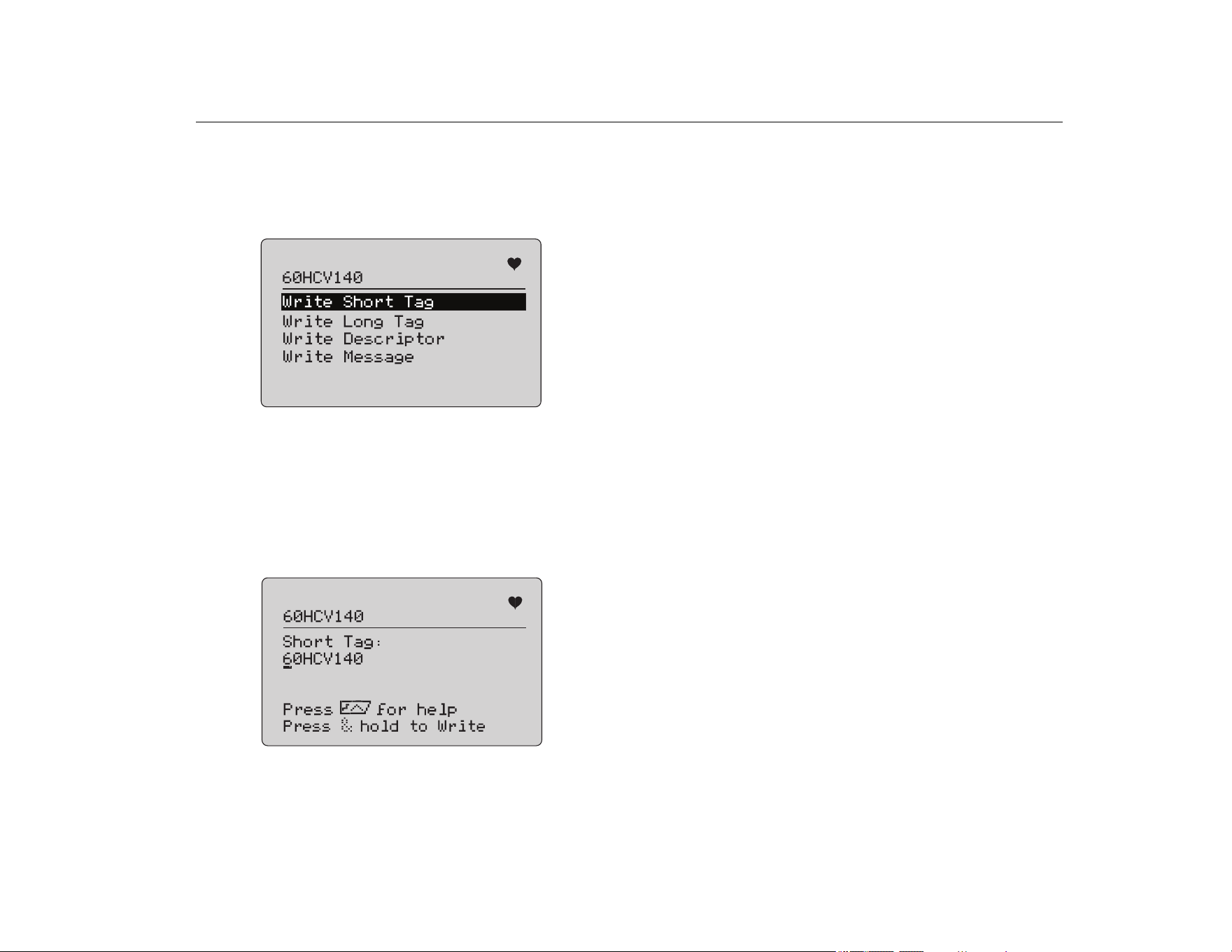
Modify Tags, Msg, Descr
Select the item to modify from the menu. See Figure 36.
Figure 36. Modify Tags, Msg, Descr
The tag name is truncated if too long to fit on one line. The
symbol in the upper right corner flashes to indicate a working
HART connection.
Rotate the selection knob to move the highlight. Push the selection
knob to move to the edit screen. See Figure 37 for an example of a
short tag.
Figure 37. Short Tag
The tag name is truncated if too long to fit on one line. The
symbol in the upper right corner flashes to indicate a working
HART connection.
The character selected for change is indicated by an underline
cursor:
• Short tag is up to 8 characters long from a limited character
set that does not include lower case.
• Long tag is up to 32 characters long from the full character
set.
• Descriptor is up to 16 characters long from a limited character
set that does not include lower case.
• Message is up to 32 characters long from a limited character
set that does not include lower case.
To modify a character:
1. Rotate the selection knob to scroll through the available
character set.
2. Push and hold the selection knob to send the new value to the
HART device and return to the Modify Setup menu.
An error shows if the HART device rejects the value for any
reason.
Tips:
• Push the selection knob to move the cursor one character
to the right.
• Push to move the cursor one character to the left.
• Push to delete the selected character.
• Push to insert a space in front of the selected
character.
• Push to show a help screen.
• Push the selection knob or
on the help screen to
resume the modification at the same position.
• Push
to return to the Modify Setup menu.
1.888.610.7664 sales@GlobalTestSupply.com
Fluke-Direct.com
709/709H/710
Users Manual
28
Trim, Set, and Zero Menu
Note
For the screens in this section, tag names can be
truncated to fit on one line. flashes in the upper-right
corner to show a live connection.
If the HART write commands are not enabled, these functions are
not available and an error message shows instead of the screen
shown in Figure 38.
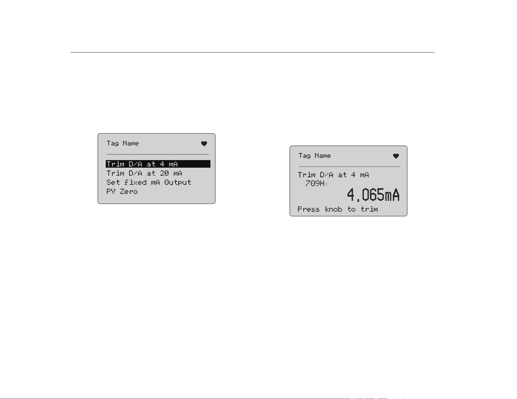
Figure 38. Trim, Set, and Zero Screen
Use the selection knob to select and start the action. Push
to
go to the Function Select menu.
Trim 4 mA
If the operation mode is Communicator Only, this function is not
available and an error message shows.
A prompt to change the loop to MANUAL before you proceed
shows. Push the selection knob to proceed. Push
to go to the
Trim, Set and Zero menu.
While the HART device is changed to fixed output mode, an error
shows if the HART device rejects the mode change command.
When the mode change is successful, the screen in Figure 39
shows.
Figure 39. Trim 4 mA Screen
While the output to settles at 4 mA, the screen shows the Product
measurement. The measurement updates once a second.
1. Push the selection knob to trim the HART device. Stay on this
screen to evaluate the result. An error shows if the HART
device rejects the trim command.
2. Push
to change the HART device to normal output mode
and go to the Trim, Set, and Zero menu. A warning to change
the loop to AUTOMATIC shows first. An error shows if the
device rejects the mode change command.
1.888.610.7664 sales@GlobalTestSupply.com
Fluke-Direct.com
Precision Loop Calibrator
Trim, Set, and Zero Menu
29
Trim 20 mA
If the operation mode is Communicator Only, this function is not
available and an error message shows.
A warning to change the loop to MANUAL before you proceed
shows. Push the selection knob to proceed. Push
to go to the
Trim, Set and Zero menu.
While the HART device is changed to fixed output mode, an error
shows if the HART device rejects the mode change command.
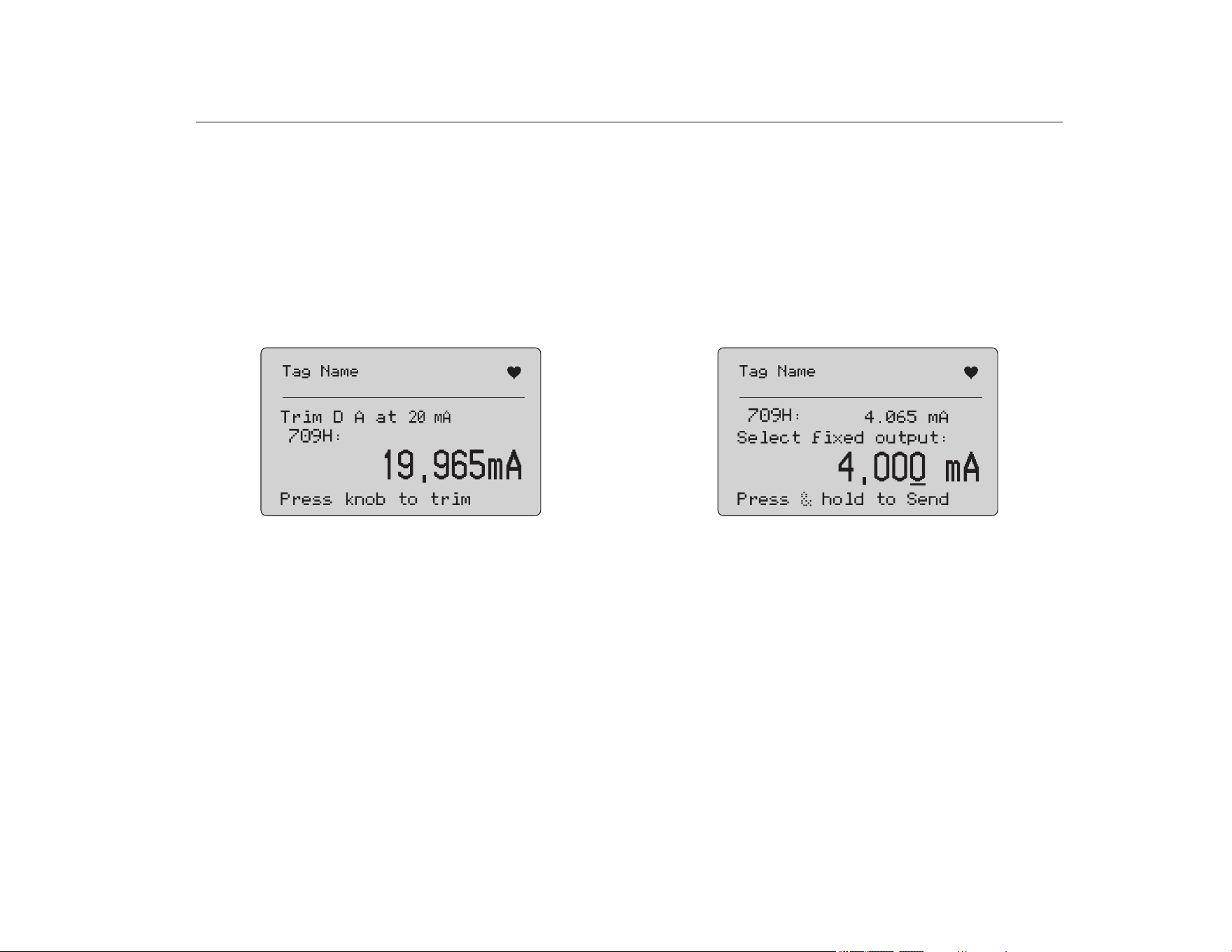
When the mode change is successful, the screen in Figure 40
shows.
Figure 40. Trim 20 mA Screen
As the output to settles at 20 mA, the screen shows the Product
measurement. The measurement is updated once a second.
1. Push the selection knob to trim the HART device. Stay on this
screen to evaluate the result. An error shows if the HART
device rejects the trim command.
2. Push
to change the HART device to normal output mode
and go to the Trim, Set, and Zero menu. A prompt to change
the loop to AUTOMATIC shows first. An error shows if the
device rejects the mode change command.
Set Fixed mA Output
If the operation mode is Communicator Only, this function is not
available and an error message shows.
A warning to change the loop to MANUAL before you proceed
shows. Push the selection knob to proceed. Push
to go to the
Trim, Set and Zero menu.
As the HART device is changed to fixed output mode, an
information screen shows. An error shows if the HART device
rejects the mode change command. When the mode change is
successful, the screen in Figure 41 shows.
Figure 41. Set Fixed mA Output Screen
This screen is used to set a fixed output and monitor the result with
the Product measurement. The measurement is updated once a
second.
The range of values that can be set is 3.0 mA to 21.0 mA.
1. Use the selection knob to select and increment or decrement
the value in steps shown by the selected decade.
2. Push and hold the selection knob to send the new value to the
HART device and stay on this screen. An error shows if the
HART device rejects the value.
3. Push
to change the HART device to normal output mode
and go to the Trim, Set, and Zero menu. A warning to change
the loop to AUTOMATIC shows first. An error shows if the
device rejects the mode change command.
1.888.610.7664 sales@GlobalTestSupply.com
Fluke-Direct.com
709/709H/710
Users Manual
30
PV Zero
A warning to change the loop to MANUAL before you proceed
shows. Push the selection knob to proceed. Push
to go to the
Trim, Set, and Zero menus.
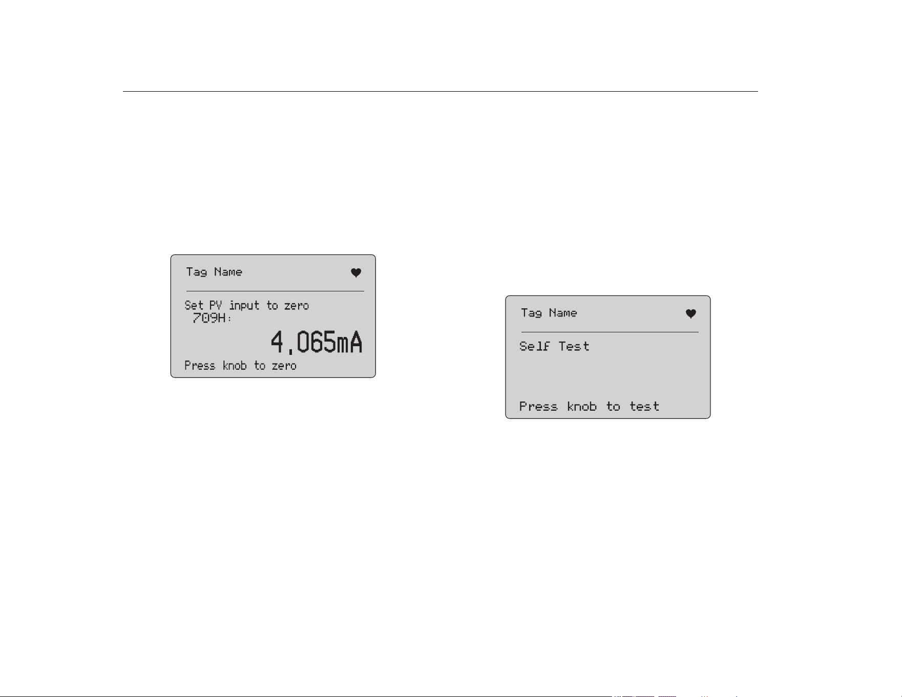
The screen in Figure 42 prompts you to set the PV process input
signal to zero and then monitors the result with the Product
measurement. The measurement updates once a second.
When the operation mode is Communicator Only, the mA
measurement is not available and the message, mA not
available, in Comm. Only mode shows instead.
Figure 42. PV Zero Screen
1. Push the selection knob to zero the HART device, and stay on
this screen to evaluate the result. An error shows if the HART
device rejects the zero command.
2. Push
to go to the Trim, Set, and Zero menu. A prompt
to restore the PV process input signal to normal operation
configuration and change the loop to AUTOMATIC shows
first.
Device Diagnostic
Note
For the screens in this section, tag names can be
truncated to fit on one line. flashes in the upper-right
corner to show a live connection.
If the HART write commands are not active, this function is not
available and an error message shows.
A warning to change the loop to MANUAL before you proceed
shows. Push the selection knob to proceed. Push
to go to the
Function Select menu.
Push the selection knob to select and start the self test. See
Figure 43.
Figure 43. Self Test Screen
When the self test is in progress, the bottom line of the screen
changes to Testing and a string of dots extends 1/second to show
the operation progress.
1.888.610.7664 sales@GlobalTestSupply.com
Fluke-Direct.com
Precision Loop Calibrator
Configuration Log and Data Log
31
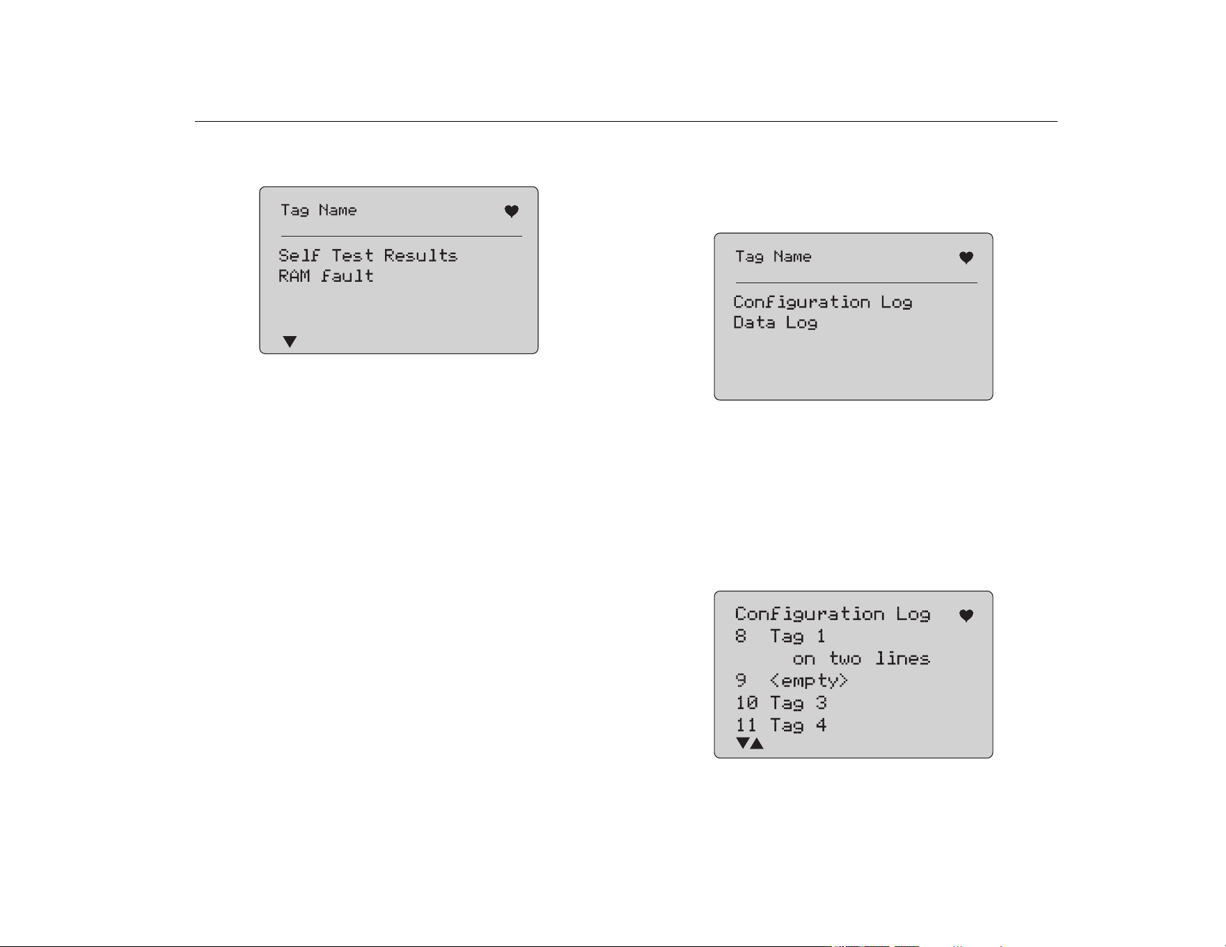
At the end of the self test, the screen in Figure 44 shows. The
screen shows No errors or the first error is reported.
Figure 44. Self Test Results Screen
The lower-left corner shows
when additional errors follow the
present error.
shows when additional errors precede the
present error.
and show when additional errors follow and
precede the present error.
1. Turn the selection knob to step between errors.
2. Push to go to the Function Select menu. A reminder to
change the loop to AUTOMATIC shows first.
Configuration Log and Data Log
Configuration Log and Data Log are available when connected to
a HART device. Use the selection knob to choose either the
Configuration Log or Data Log. See Figure 45.
Figure 45. Data Log and Configuration Log Screen
Configuration Log
Configuration data for a maximum of 20 tags can be stored for
later recall. The configuration data saved is the same as that
shown on the Device Data screen.
The initial Configuration Log screen spans more than one screen
and shows a list of the tags held in storage. If a storage position is
not used, the tag name area shows <empty>. See Figure 46.
Figure 46. Configuration Log Screen
1.888.610.7664 sales@GlobalTestSupply.com
Fluke-Direct.com
709/709H/710
Users Manual
32
After a storage position is selected, data can be saved or recalled
from it. It can be erased or sent to the USB port.
Note
With the 710, you can upload data to a PC with the
ValveTrack Windows Software and included USB
communications cable.
To select:
1. Use the selection knob to highlight and select the correct
storage location.
2. Push
to go to the Log Select menu.
When a storage position is selected, the menu in Figure 47
shows.
3. Select the action.
Figure 47. Configuration Log Showing Storage Position
The number and contents of the storage position show at the top.
The tag number is <empty> if the storage position is empty.
Use the selection knob to highlight and select the correct function.
Push
to go to the Log Select menu.
SAVE operation:
• If the position is empty, save the present device configuration
data into the storage position.
• If the position is in use, confirm that the existing data is to be
replaced with the present tag data before you save it into the
storage position.
RECALL operation:
• If the position is empty, an error message shows.
• If the position is in use, the data shows in a sequence of
screens identical to the Device Data screen.
ERASE operation:
• If the position is empty, an error message shows.
• If the position is in use, confirm that the existing data is to be
permanently deleted before doing so.
SEND operation:
• If the position is empty, an error message shows.
• If the position is in use, send the data to the RS232 port in a
report format.
Data Log
Process data can be stored for a single tag for later upload to a PC
with the ValveTrack Windows Software. See Configuration Log.
Data can be logged in multiple sessions, but all sessions must be
from the same HART device as determined by the long tag name.
A different logging interval can be selected for each session. Each
data sample has the Product measurement, device mA, and all
four process variables.
There are 9810 records available. See Figure 48. Each data
sample uses one record.Each session uses two records for
overhead data that is common to all of the data samples in that
session.There can be from 1 to 99 sessions.
1.888.610.7664 sales@GlobalTestSupply.com
Fluke-Direct.com
Precision Loop Calibrator
Configuration Log and Data Log
33
The total number of data samples that can be logged:
• 709H - 9810 (less 2 x the number of sessions started and
stopped)
• 710 - 4910
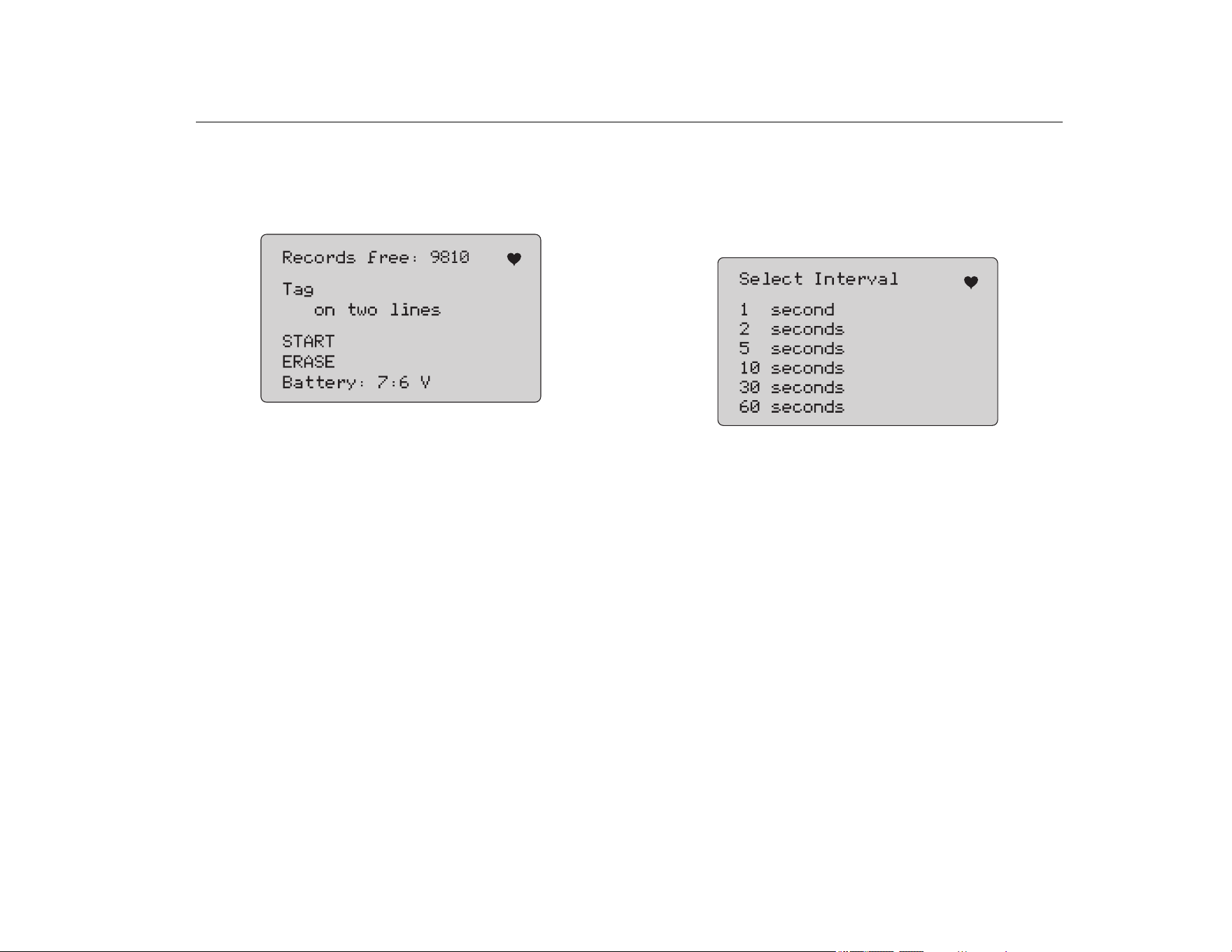
Figure 48. Data Log Screen
The number of free records show on the first line. If data has
already been logged, the tag number shows below it.
The present battery voltage shows at the bottom to indicate if the
batteries should be changed before a log session starts. The log is
stopped before the Product is turned off when the battery reaches
its low voltage automatic shutoff limit of 5.6 V.
1. Use the selection knob to highlight and select the function.
2. Push the knob to do the operation.
3. Push
to return to the Log Select menu.
START operation:
• If no free records or free sessions remain, or the present
HART device does not match the HART device already
logged, an error message shows.
• Otherwise, proceed to interval selection described below.
ERASE operation:
• If there is no logged data, an error message shows.
• Otherwise, confirm that the present data is to be permanently
erased before doing so.
4. Select the logging interval. See Figure 49.
Figure 49. Logging Interval Screen
5. Turn the selection knob to move the highlight and select the
interval.
6. Push the selection knob to start logging at that interval.
7. Push
to go to the first data log screen.
1.888.610.7664 sales@GlobalTestSupply.com
Fluke-Direct.com
709/709H/710
Users Manual
34
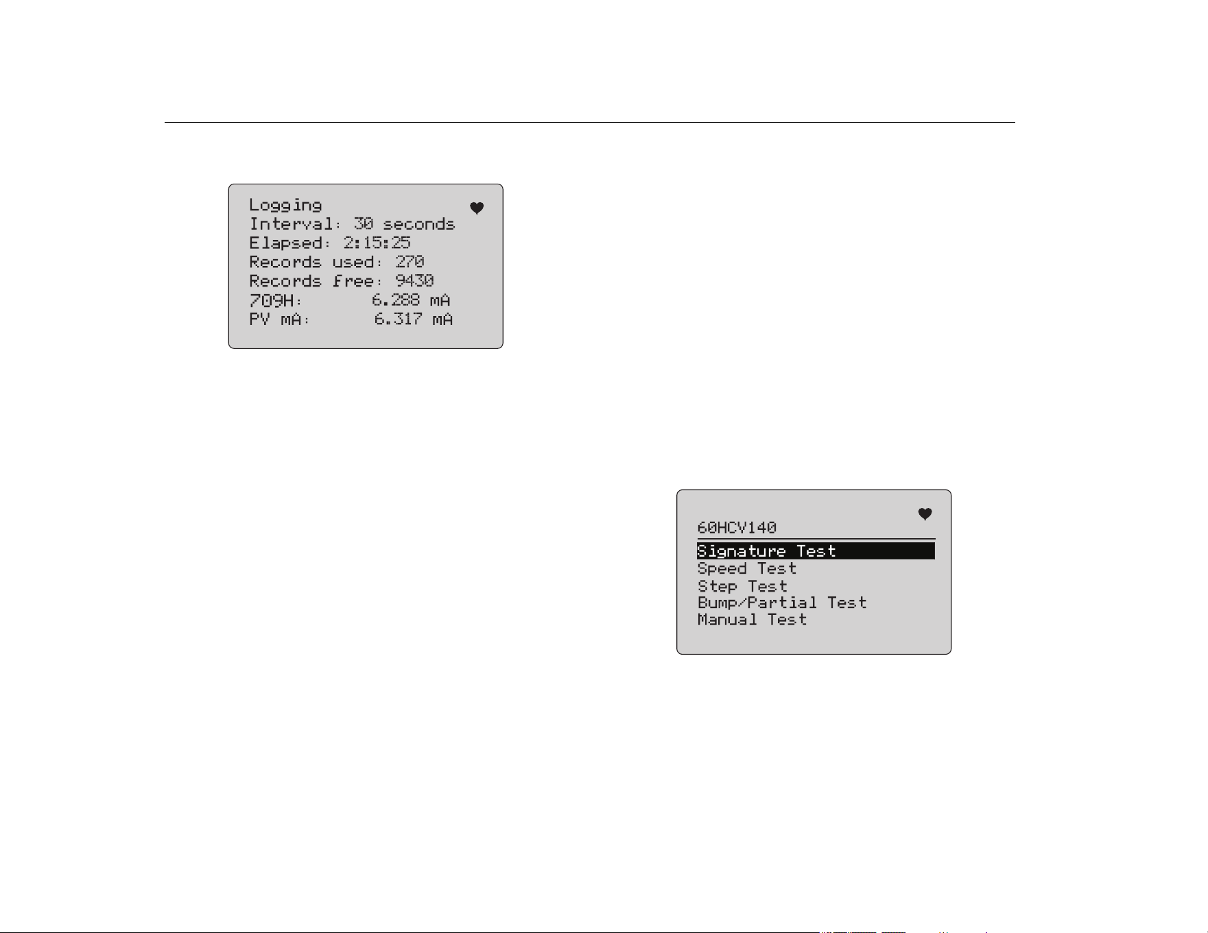
While logging, the screen in Figure 50 shows to monitor
progress.
Figure 50. Active Logging Screen
8. Push
to stop logging and go to the first data log screen.
The data items are:
• The top line indicates is logging is in progress (Logging) or is
stopped (Stopped). Logging stops automatically when storage
is full or before the Product is turned off when the battery
reaches its low voltage automatic shutoff limit of 5.6 V.
• Interval is the item previously selected.
• Elapsed is the time since the log was started, updated each
time a new sample is saved.
• Records used is the total number used to date for all sessions,
updated each time a new sample is saved.
• Records free is the total number that remain unused, updated
each time a new sample is saved.
• 709H is the present measurement, updated as often as
possible.
• PV mA is the last HART device measurement, updated as
often as possible.
Valve Tests (710)
The 710 adds specialty tests to the basic HART functionality of the
709H to perform tests on HART smart valve positioners.
1. Connect to the control valve.
2. Push
.
3. Turn the selection knob to move the highlight to HART Comm
menu and push the selection knob to select.
4. Push the selection knob to select the option.
5. Rotate the selection knob to highlight mA Src. - HART Valve
and push the knob to make the selection.
6. Select HART CONNECT to initiate HART polling for
connected HART devices.
7. When the 710 finds a device, push the selection knob to
select.
8. From the HART Valve operation screen, select Valve Tests.
See available options for valve tests in Figure 51.
Figure 51. Valve Tests
1.888.610.7664 sales@GlobalTestSupply.com
Fluke-Direct.com
Precision Loop Calibrator
Valve Tests (710)
35
Signature Test
In the Signature Test, the product sources a ramping 4 mA to
20 mA to 4 mA signal and records the pressure applied to the
actuator from the positioner and the position.
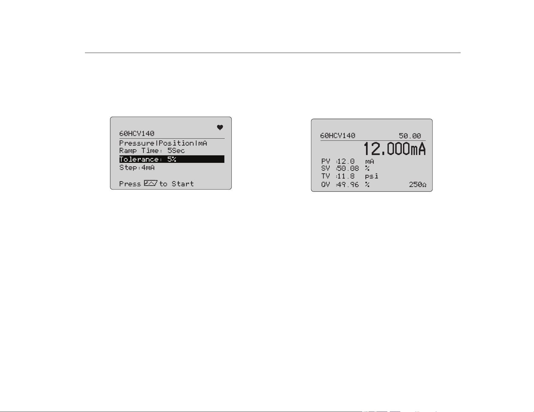
To set up:
1. Go to Signature Test Menu. See Figure 52.
Figure 52. Signature Test Setup
2. Push the knob to move the cursor through the options.
3. Confirm the Ramp Time, change if needed.
4. Change the Tolerance as required from 1 % to 20 %.
5. In the Calibrator Setup Menu, select Test Tolerance > Valve
Test Parameters to set the default test tolerances.
6. Change the size of steps as required from 0.1 mA to 4.0 mA.
To run the test:
1. Push to start the test.
The Product varies the 4 to 20 mA signal, monitors the TV and
QV variables (pressure and position), and compares it to
expected values.
• Good test result: the position variable is as expected.
• Marginal test result: the position variable value is found to
be close to the test tolerance.
• Bad test result: the position variable deviation values vary
greater than the tolerance.
2. Select Save to save the test results and upload later to the
ValveTrack software.
Or, select Discard if you do not want to save the test result.
Manual Test
Select Manual Test to see the mA signal applied and HART
variables. See Figure 53.
Figure 53. Manual Test
The HART variables that show on the display are important
information about the operation of the valve.
HART variable mapping:
PV: Digitized mA value that represents the mA value applied to the
valve.
Note
This value should agree closely with the applied mA
value.
SV: Setpoint where the valve is expected to be at in % of travel.
Valves forward acting are configured to Fail Open (FO) as the 4 to
20 mA signal moves the valve from 0 % to 100 % of travel (from
open to closed) with 4 to 20 mA signals applied. If the valve is
configured as FC and is forward acting, the valve opens as the
applied mA signal increases to 20 mA.
1.888.610.7664 sales@GlobalTestSupply.com
Fluke-Direct.com
709/709H/710
Users Manual
36
If the positioner is configured to be reverse acting, the relationship
of mA signal to control valve opening and closing is reversed.
Configuration for forward or reverse action does not change the
mode in which the valve fails.
TV: This variable is the pressure applied to the pneumatic actuator
by the valve positioner. With 4 mA applied in a Direct Acting
positioner, the minimum or 0 psi of pressure is applied and the
valve spring holds the valve into the failure mode position (FO or
FC). With 20 mA applied, the direct acting actuator has maximum
pressure applied to the actuator from the positioner moving it to
the 100 % position and the opposite of the failure position.
Reverse acting actuators respond opposite of direct acting
actuators with 4 to 20 mA signals applied.
QV: This is the position feedback variable (0 % to 100 %). The
position feedback variable should agree closely with the Setpoint
variable (SV). If it does not, the positioner should be calibrated to
better match the position of the valve or repair is required.
To run the manual test:
1. Push the , and to change the valve position and
the mA output.
2. Manually compare the variable to what is expected.
Note
When the Valve Test is set to ON (Figure 13),
changes the mA signals to step with stops at 3.8 mA,
4.2 mA, 19.8 mA, and 20.2 mA to make manual valve
testing easier (see Valve Test).
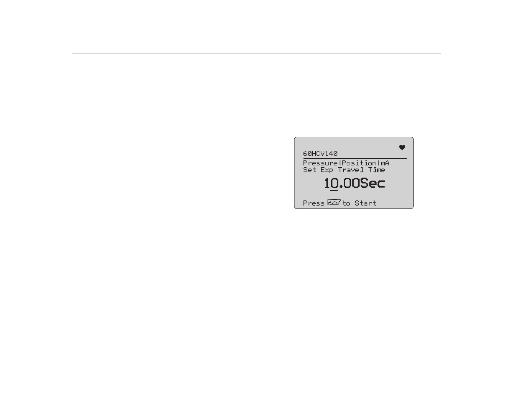
Speed Test
The Speed Test is a test of the time it takes to open and close the
valve.
To set up the expected time to cycle the valve in seconds from
10 seconds and up:
1. Move the cursor to the digit to change.
2. Rotate the selection knob to change the time value.
3. Push the selection knob to input the change.
Figure 54. Speed Test
To run the test:
1. Push to start the test.
• Good test result: the position variable is as expected.
• Marginal test result: the position variable value is found to
be close to the test tolerance.
• Bad test result: the position variable deviation values vary
greater than the tolerance.
2. Select Save to save the test results and upload later to the
ValveTrack software.
Or, select Discard if you do not want to save the test result.
1.888.610.7664 sales@GlobalTestSupply.com
Fluke-Direct.com
Precision Loop Calibrator
Valve Tests (710)
37
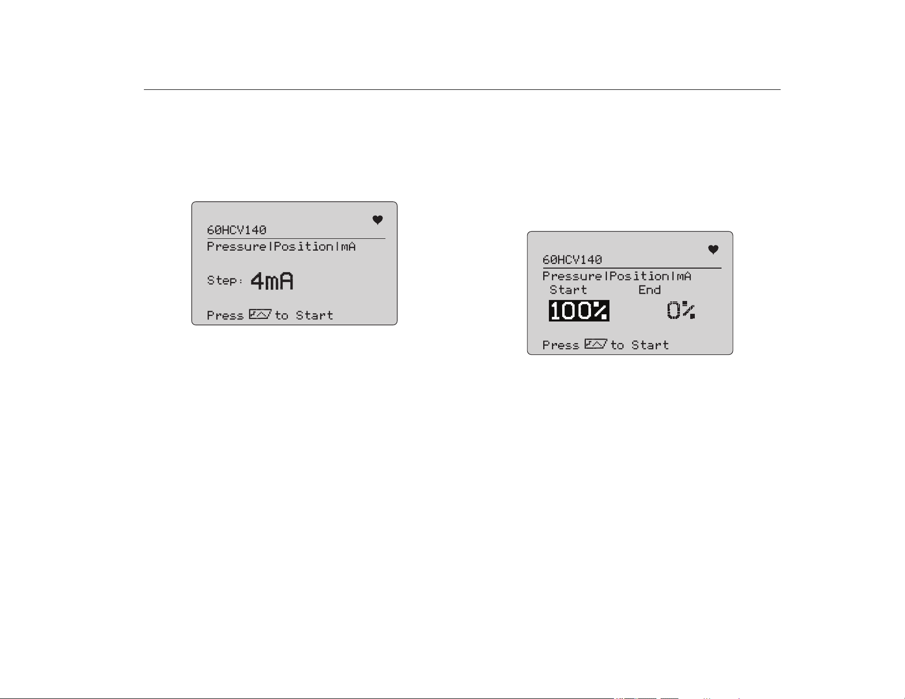
Step Test
In this test the mA signal is changed in steps and compared to the
position variable (QV).
To set up the step size for the test from 0.1 mA to 4 mA, rotate the
selection knob to change the mA value.
Figure 55. Step Test
To run the test:
1. Push to start the test.
• Good test result: the position variable is as expected.
• Marginal test result: the position variable value is found to
be close to the test tolerance.
• Bad test result: the position variable deviation values vary
greater than the tolerance.
2. Select Save to save the test results and upload later to the
ValveTrack software.
Or, select Discard if you do not want to save the test result.
Bump/Partial Test
The Bump/Partial Test is a test of the valve over a smaller portion
of the stroke, or bump the mA value, to find if the valve moves as
expected. This is also done with a Manual Test of the position or
other values.
To set up:
1. Set the start and stop stroke values in % of travel.
Figure 56. Bump/Partial Test
To run the test:
1. Push to start the test.
• Good test result: the position variable is as expected.
• Marginal test result: the position variable value is found to
be close to the test tolerance.
• Bad test result: the position variable deviation values vary
greater than the tolerance.
2. Select Save to save the test results and upload later to the
ValveTrack software.
Or, select Discard if you do not want to save the test result.
1.888.610.7664 sales@GlobalTestSupply.com
Fluke-Direct.com
709/709H/710
Users Manual
38
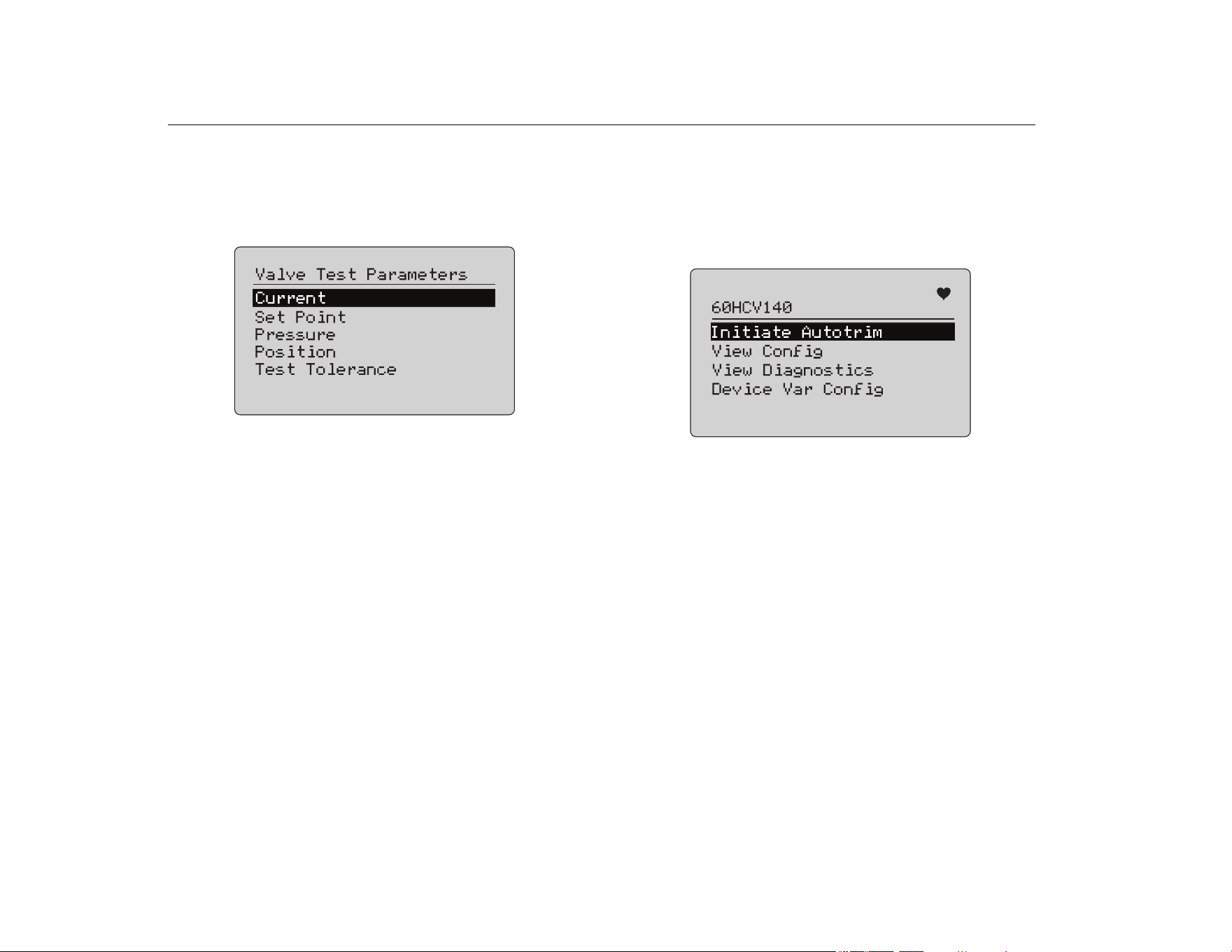
Test Configuration Screens
Use the configuration screens to set the default tolerance of the
tests:
1. In the calibrator Setup Menu (see Figure 9), select Valve Test
Parameters to review the variable mapping. See Figure 57.
Figure 57. Valve Tests
To set the Test Tolerance:
1. Go to Valve Test Parameters > Test Tolerances.
2. Change the individual test tolerances from 1 % to 20 %.
HART Comms Menu
Use the HART Comms Menu to start autotrim and view device
variables and status:
1. Connect to the HART valve.
2. Go to Modify Setup > HART Comms. See Figure 58 for the
available options.
Figure 58. HART Comms. Menu
• Initiate Autotrim: Use to autotrim the positioner. At the
end of the autotrim, the valve position is set to 50 % and
you can quickly decide if additional trimming is required.
• View Config: Supports only HART 7 devices. Use to
show the device variable classification of PV, SV, TV and
QV. Examples include:
• Pressure
• Volume Flow
•Mass Flow
If HART 7 is not supported by the device, the display
shows a warning message.
• View Diagnostics: Supports only HART 7 devices. Use to
show the status of the PV, SV, TV, and QV variables (for
example, BAD, MARGINAL, or GOOD). If HART 7 is not
supported by the device, the display shows a warning
message.
• Device Var Config: Use to view the PV, SV, TV and QV
variables of the device.
1.888.610.7664 sales@GlobalTestSupply.com
Fluke-Direct.com
Precision Loop Calibrator
Valve Tests (710)
39
Valve Test Quick Start Guide
1. Power up the 710.
a. Disconnect the mA input wires to valve if connected to a
circuit.
b. Connect the output leads from the 710 in place of the
signal wires (likely to be a bench check and not
connected to the control system).
c. To move the valve, connect the valve to regulated air
supply (house air or other compressed air supply).
2. Push
and select HART Comm Menu.
3. Select HART Comm Menu > HART Connect.
4. Rotate the selection knob to Mode and push the selection
knob to input the change.
5. Select mA Src. – HART Valve > Connect.
a. Wait for the 710 to find the valve through HART
communication.
b. Once the 710 display shows Found 1 device, push the
selection knob to input the change.
6. Select Valve Tests > Signature Test.
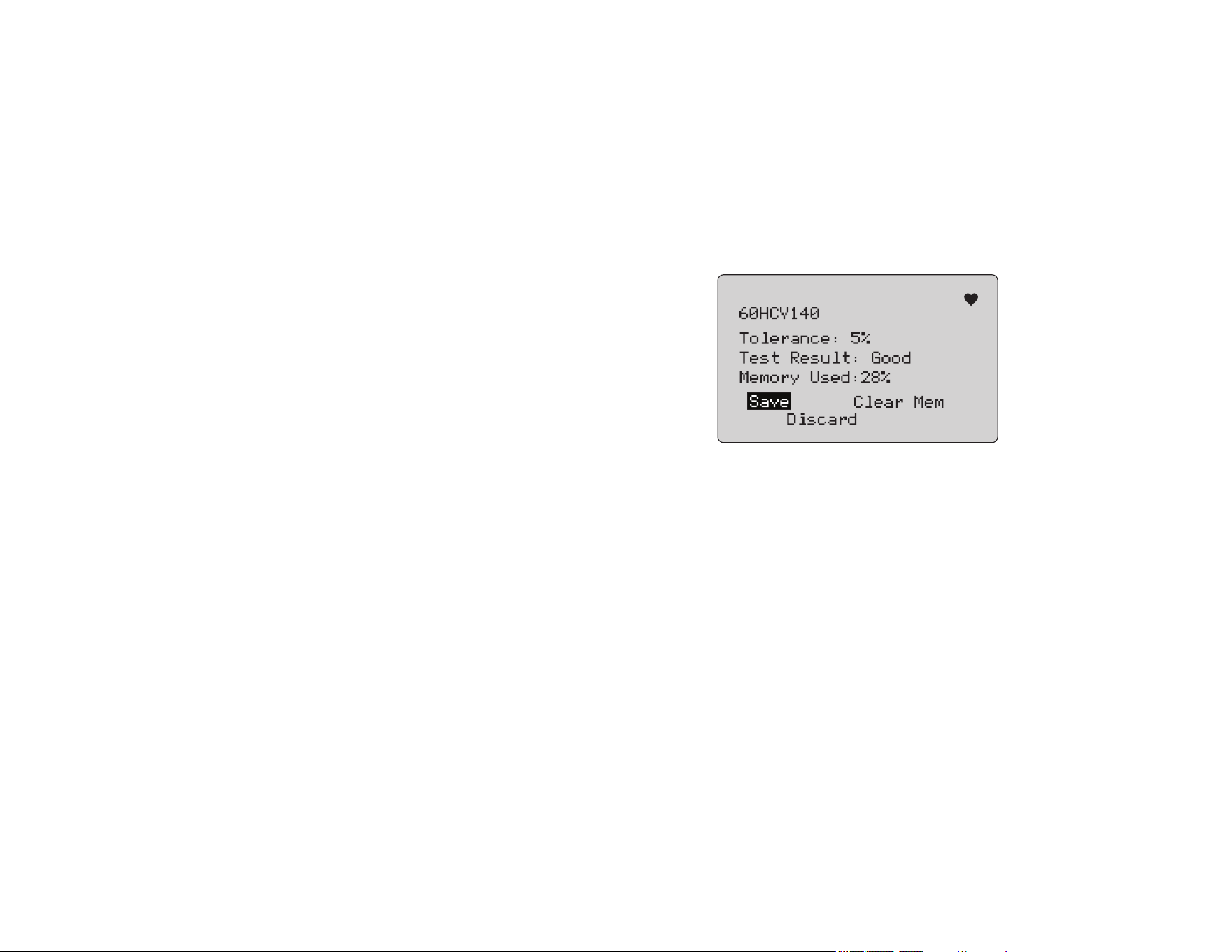
7. Push to start the test. See Figure 59.
• Good test result: the position variable is as expected.
• Marginal test result: the position variable value is found to
be close to the test tolerance.
• Bad test result: the position variable deviation values vary
greater than the tolerance.
Figure 59. Test Results
To continue, use Manual Test to see the real-time HART variables
for position and pressure (rotate the knob) as you change the mA
output signal (push , and to change the mA value).
1.888.610.7664 sales@GlobalTestSupply.com
Fluke-Direct.com
709/709H/710
Users Manual
40
Maintenance
XW Warning
For safe operation and maintenance of the
Product:
• Repair the Product before use if the battery
leaks.
• Be sure that the battery polarity is correct to
prevent battery leakage.
• Remove the input signals before you clean the
Product.
• Use only specified replacement parts.
• Have an approved technician repair the Product.
Clean the Product
Clean the Product and pressure modules with a soft cloth
dampened with water or water and mild soap.
W Caution
To prevent possible damage to the Product:
• Do not use solvents or abrasive cleansers.
• Do not allow water into the case.
Fuse
The Product is protected from overcurrent condition by an internal
self-resetting fuse. The fuse will automatically reset within a few
seconds. The fuse cannot be repaired manually.
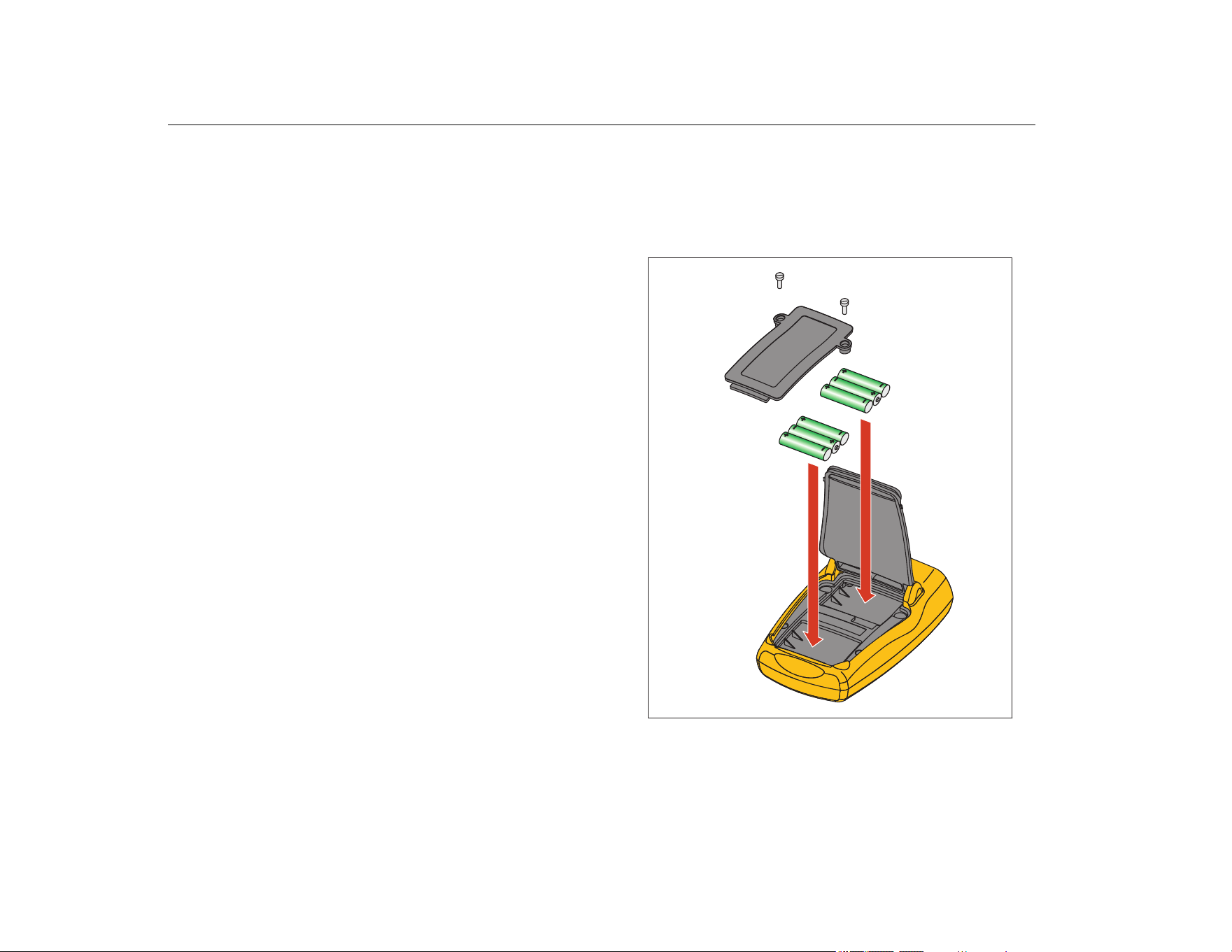
Battery Replacement
Replace the batteries when the battery indicator shows on the
display.
To replace the batteries:
1. Turn the Product over so the display is face down.
2. Lift bail to access the battery door. See Figure 60.
3. With a flat-head screwdriver, remove the battery door screws.
4. Remove the batteries.
5. Replace the old batteries. Note the correct polarity as the new
batteries are installed.
6. Attach the battery door.
7. Replace and tighten the two battery door screws.
Figure 60. Battery Replacement
1.888.610.7664 sales@GlobalTestSupply.com
Fluke-Direct.com
Precision Loop Calibrator
User-Replaceable Parts
41
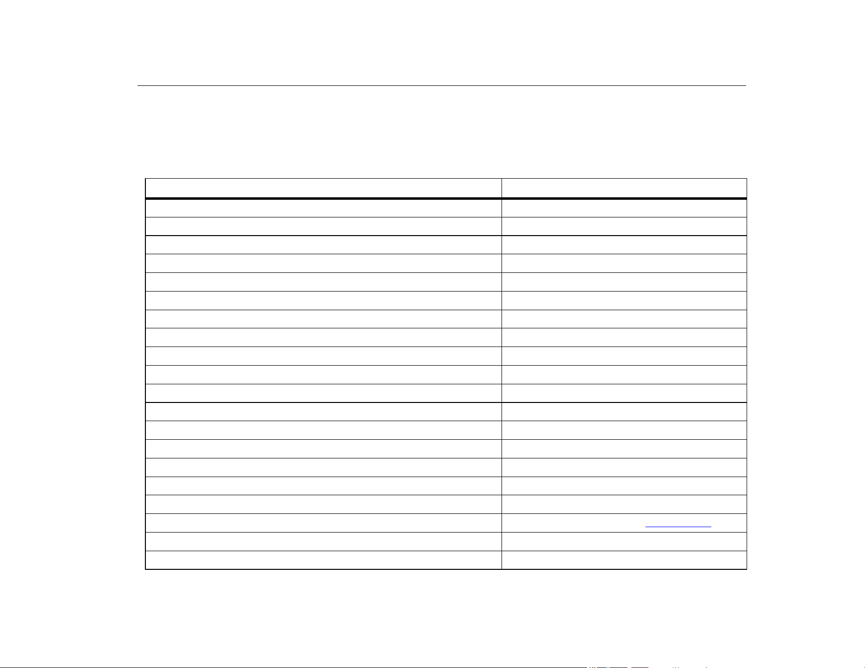
User-Replaceable Parts
Table 5 is a list of user-replaceable parts. For more information
about these items and their prices, contact a Fluke representative.
Table 5. User-Replaceable Parts
Item Fluke Part Number
Fluke-709-2005, Knob 4282155
Fluke-709-2001, Case Top 4440380
Fluke-709-2002, Case Bottom 4440371
Fluke-709-2003, Battery Door 4440405
Fluke-709-2004, Connector Panel 4440398
Fluke-709-2006, Holster, Fluke-709 4241437
Fluke-709H-2006, Holster, Fluke-709H 4241443
Fluke-709-2007, Bail, Fluke709/709H 4241455
Fluke-709-8003, Keypad, Fluke-709/709H 4252551
TL75-4201, Test Leads 855742
AC280 Suregrip Hook Clip (black) 2063165
AC280 Suregrip Hook Clip (red) 1613782
TP220 Test Probes (red) 2047206
TP220 Test Probes (black) 2063129
Alligator Clip Set, Extended Tooth 3765923
Stackable Lead Set 3669716
USB to 5-Pin Cable, 6-ft 4401616
710 ValveTrack Software
709H/TRACK, Datalogging Software & Cable 4281225
Softcase 2643273
1.888.610.7664 sales@GlobalTestSupply.com
Fluke-Direct.com

709/709H/710
Users Manual
42
Specifications
Ranges
mA ........................................... 0 mA to 24 mA
Volts......................................... 0 V dc to 30 V dc
Resolution
mA Ranges .............................. 1 µA
Voltage Range ......................... 1 mV
Accuracy......................................... 0.01 % ±2 LSD all ranges (@23 °C ±5 °C)
Stability........................................... 20 ppm of F.S. /°C from -10 °C to 18 °C and 28 °C to 55 °C
Operating Temp Range.................. -10 °C to 50 °C (14 °F to 122 °F)
Storage Temp Range ..................... -20 °C to 60 °C (-4.0 °F to 140 °F)
Altitude ........................................... 3000 meters
Ingress Protection Rating ............... IEC 60529: IP40
Humidity Range.............................. 10 % to 95 % non-condensing
Display............................................ 128 x 64 pixels, LCD Graphic with backlight, 8.6 mm high digits
Power ............................................. Six IEC LR03 batteries
Battery Life (Alkaline Batteries)...... ≥40 hours continuous use (measure mode)
Loop Compliance Voltage .............. 24 V dc @ 20 mA
Loop Drive Capability ..................... 1200 Ω without HART resistor, 950 Ω with HART resistor
Dimensions (LxWxD)...................... (152 x 93 x 44) mm, (6.0 x 3.7 x 1.7) in
Weight ............................................ 0.3 kg (9.5 oz)
1.888.610.7664 sales@GlobalTestSupply.com
Fluke-Direct.com

Precision Loop Calibrator
Specifications
43
Safety ............................................. IEC 61010-1: Pollution Degree 2
Electromagnetic Compatibility (EMC)
International ............................. IEC 61326-1: Portable Electromagnetic Environment IEC 61326-2-2
CISPR 11: Group 1, Class A
Group 1: Equipment has intentionally generated and/or uses conductively-coupled radio
frequency energy that is necessary for the internal function of the equipment itself.
Class A: Equipment is suitable for use in all establishments other than domestic and those
directly connected to a low-voltage power supply network that supplies buildings used for
domestic purposes. There may be potential difficulties in ensuring electromagnetic compatibility
in other environments due to conducted and radiated disturbances.
Caution: This equipment is not intended for use in residential environments and may not provide
adequate protection to radio reception in such environments.
Emissions that exceed the levels required by CISPR 11 can occur when the equipment is
connected to a test object.
Korea (KCC) ............................ Class A Equipment (Industrial Broadcasting & Communication Equipment)
Class A: Equipment meets requirements for industrial electromagnetic wave equipment and the
seller or user should take notice of it. This equipment is intended for use in business
environments and not to be used in homes.
USA (FCC)............................... 47 CFR 15 subpart B. This product is considered an exempt device per clause 15.103.
1.888.610.7664 sales@GlobalTestSupply.com
Fluke-Direct.com