Loading ...
Loading ...
Loading ...
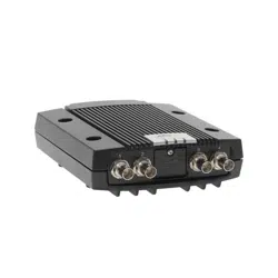
AXIS Q7424–R0N,,
Hardware Overview
NOTICE
To prevent corruption of recordings, the SD card should be unmounted before removal. To unmount, go to Setup > System
Options > Storage > SD Card a n d click Unmount.
Control button - The control button is u sed for:
• ConnectingtoanAXISVideoHostingSystemservice.See
page 40
. To connect, press and hold the button for about
1 second until the Status LE D flashes green .
• ConnectingtoAXISInternetDynamicDNSService. See
page 40
. To connect, press and hold the button for
about 3 seconds.
• Resetting the p rod uct to fa ctory default settings. See
page 47
.
Power connector - 3-pin terminal blo ck for power input.
I/O terminal connector - Use in applicat ions for e.g. motion detection, event triggering, time lapse recording and alarm notifications.
In addition to an auxili ary pow e r and a GND pin, the I/O terminal connector provides the interface to:
• Digital output — For conne cting exte rnal devices such as rela ys and LEDs. Connecte d devices can be activated by
the VAPIX® Application Programming Interface, output b uttons on the Live View page or by an Actio n Rule. The
output will show as active (shown under System Options > Ports & Devices) if the alarm device is activated.
• Digital input — An alarm input for connecting devices tha t can toggle between an open and closed circuit, for
example: PIRs, door/window contacts, glass break detectors, etc. When a signal is received the state changes and
the input becomes active (shown under System Options > Ports & Devices).
RS-485/RS-422 connector - Tw o 2-pin terminal blocks for RS -485/R S-422 serial interface used to control auxiliary eq uipment,
e.g. PTZ devices.
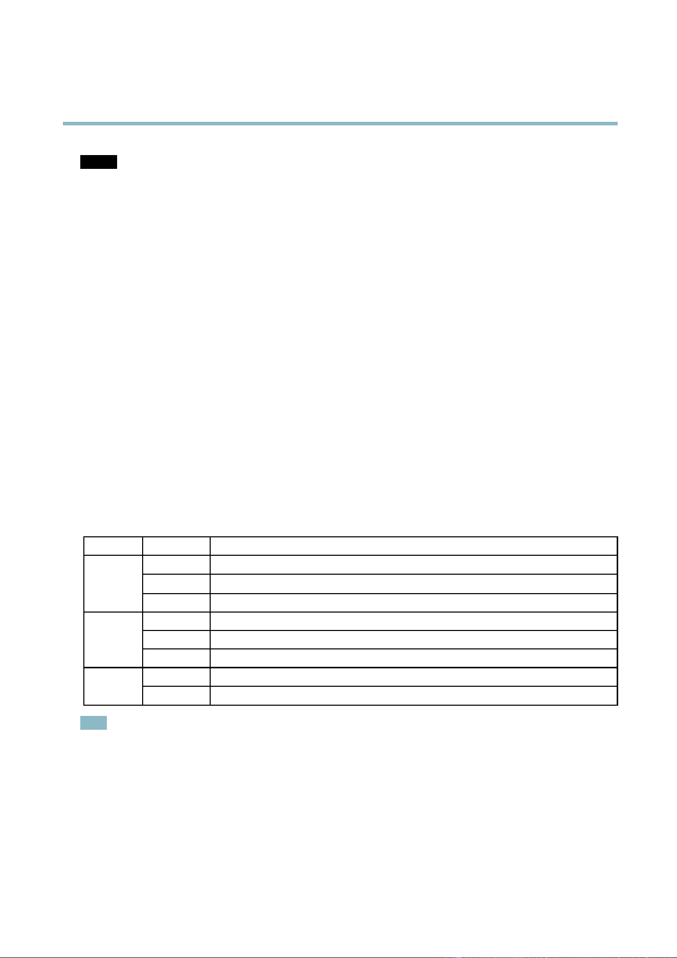
LED Indicators
LED
Color
Indication
Green
Steady for connection to a 1 GBit/s network. Flashes for network activity.
Amber
Steady for connection to a 10/100 MBit/s network. Flashes for network activity.
Network
Unlit No network connection.
Green Steady g reen for normal operation.
Amber
Steady during startup and when restoring settings.
Status
Red
Slow flash for faile d u
pgrade.
Green
Normal operation.
Power
Amber
Flashes green/amber during firmware upgrade.
Note
• The Status LED can be configured to flash while an event is active.
• The S tatus LED can be configured to flash for identifying the unit. This can be done under Setup > System Options >
Maintenance.
6
Loading ...
Loading ...
Loading ...