Loading ...
Loading ...
Loading ...
AXIS Q7424–R0N,,
Hardware Overview
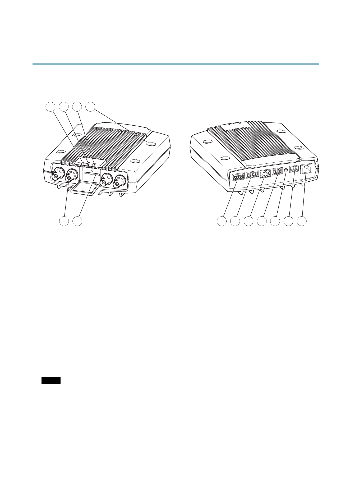
Hardware Overview
5 6 7 8 9
21 3 4
10 11 12 13
1.
LED i ndicator power
2.
LED indicator status
3.
LED indicator network
4.
Mounting holes
5.
Video input connectors
6.
SD memory card slot
7.
I/O connector
8.
Audio connectors
9.
SFP co nnector
10.
RS-485/RS-422 connector
11.
Control button
12.
Power connector
13.
Network connector (PoE)
Connectors
For technical specifications, see
page 53
.
Network connector - RJ-45 Ethernet c onnector. Supports P ower over Ethernet (PoE).
SFP connector - The unit can only use one Network interface, either an SFP module or RJ–45 connector. SFP module has higher
priority than the RJ–45 connector.
NOTICE
Due to local regulations or the environmental and electrical conditions in which the product is to be used, a shie lde d
network cable (STP) may be appropriate or required. Any network cables that are routed in outdoor environments or similar
shall be shielded (STP) and intended for their specific use. Make sure that the network switch is properly grounded. See
Electromagnetic Compatibility (EM C )
for regulatory requirements.
Au
dio terminal connector - 4–pin terminal block for audio input and output.
SD card slot - A standard or high-capacity SD card (not included) can be used for local recording with removable storage.
5
Loading ...
Loading ...
Loading ...