
Loading ...
Loading ...
Loading ...
SDS5000X Series Digital Oscilloscope User Manual
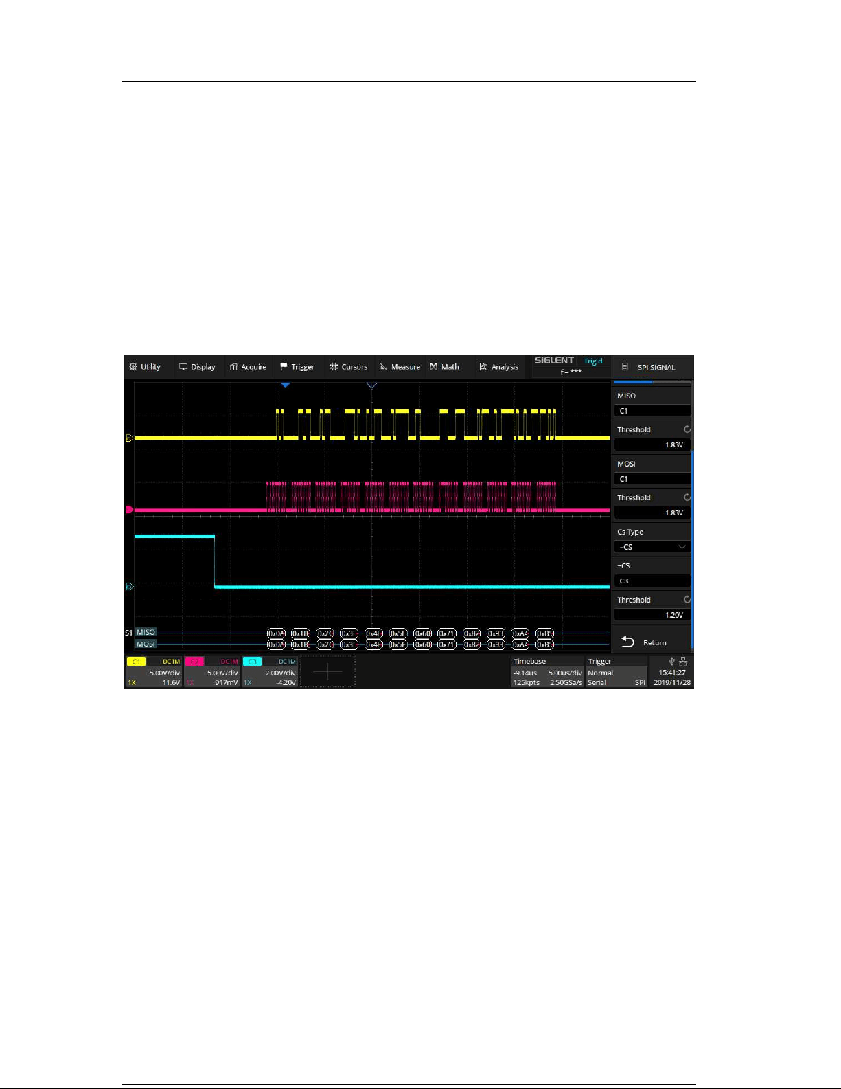
Connect the data, CLK and ~CS signals of a SPI bus respectively to C1, C2
and C3. Data width = 8-bit, Bit order = MSB, CS polarity = active low, and 12
data bytes are transmitted in one frame.
In the SPI trigger signal menu, set the source and threshold of CLK, MISO and
CS signals, then copy the trigger settings to decoding. Adjust the timebase, so
that there is a falling edge on CS signal shown in the screen:
When the CS type is set to Clock Timeout, turn on Cursor, measure the clock
idle time between frames as 150 us, and measure the interval between clock
pulses as 0.14 us, then set the timeout to a value between 0.14 and 150 us. In
this example it is set to 500 ns:
Loading ...
Loading ...
Loading ...