Loading ...
Loading ...
Loading ...
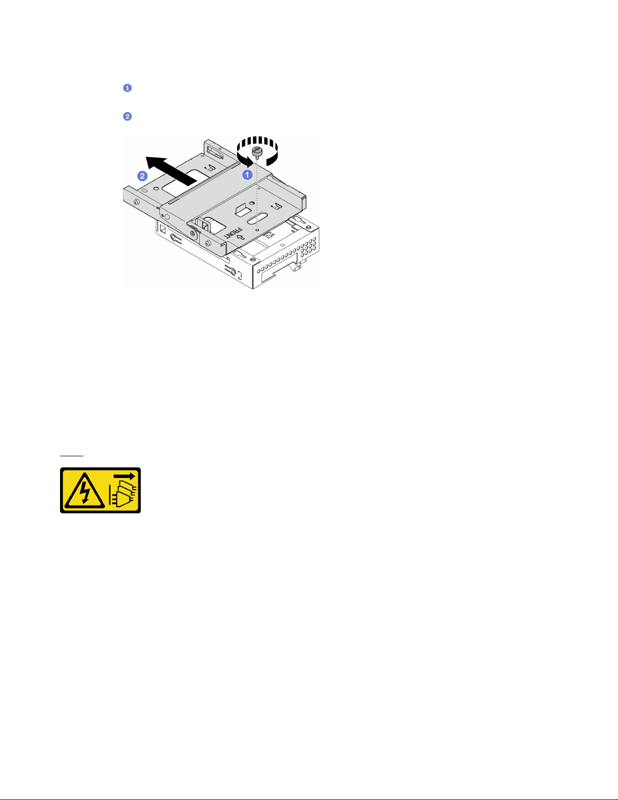
Step 2. Remove the 3.5-inch drive cage from the optical drive cage.
a.
Remove the screw that secures the 3.5-inch drive cage to the optical drive cage. Reserve
the screw to be used for reinstalling the 3.5-inch drive cage..
b.
Slide the optical drive cage to separate it from the 3.5-inch drive cage.
Figure 50. Removing the 3.5-inch drive cage from the optical drive cage
After you finish
1. Install a new 3.5-inch drive cage, see
“Install the drive cage (bay 3)” on page 68.
2. If you are instructed to return the component or optional device, follow all packaging instructions, and
use any packaging materials for shipping that are supplied to you.
Install the drive cage (bay 3)
Follow this procedure to install the drive cage to bay 3.
S002
CAUTION:
The power-control button on the device and the power switch on the power supply do not turn off the
electrical current supplied to the device. The device also might have more than one power cord. To
remove all electrical current from the device, ensure that all power cords are disconnected from the
power source.
About this task
Attention:
• Read
“Safety inspection checklist” on page iv and “Installation guidelines” on page 41 to ensure that you
work safely.
• Touch the static-protective package that contains the component to any unpainted metal surface on the
server; then, remove it from the package and place it on a static-protective surface.
Watch the procedure
68
ThinkSystem ST50 V2 Maintenance Manual
Loading ...
Loading ...
Loading ...