Loading ...
Loading ...
Loading ...
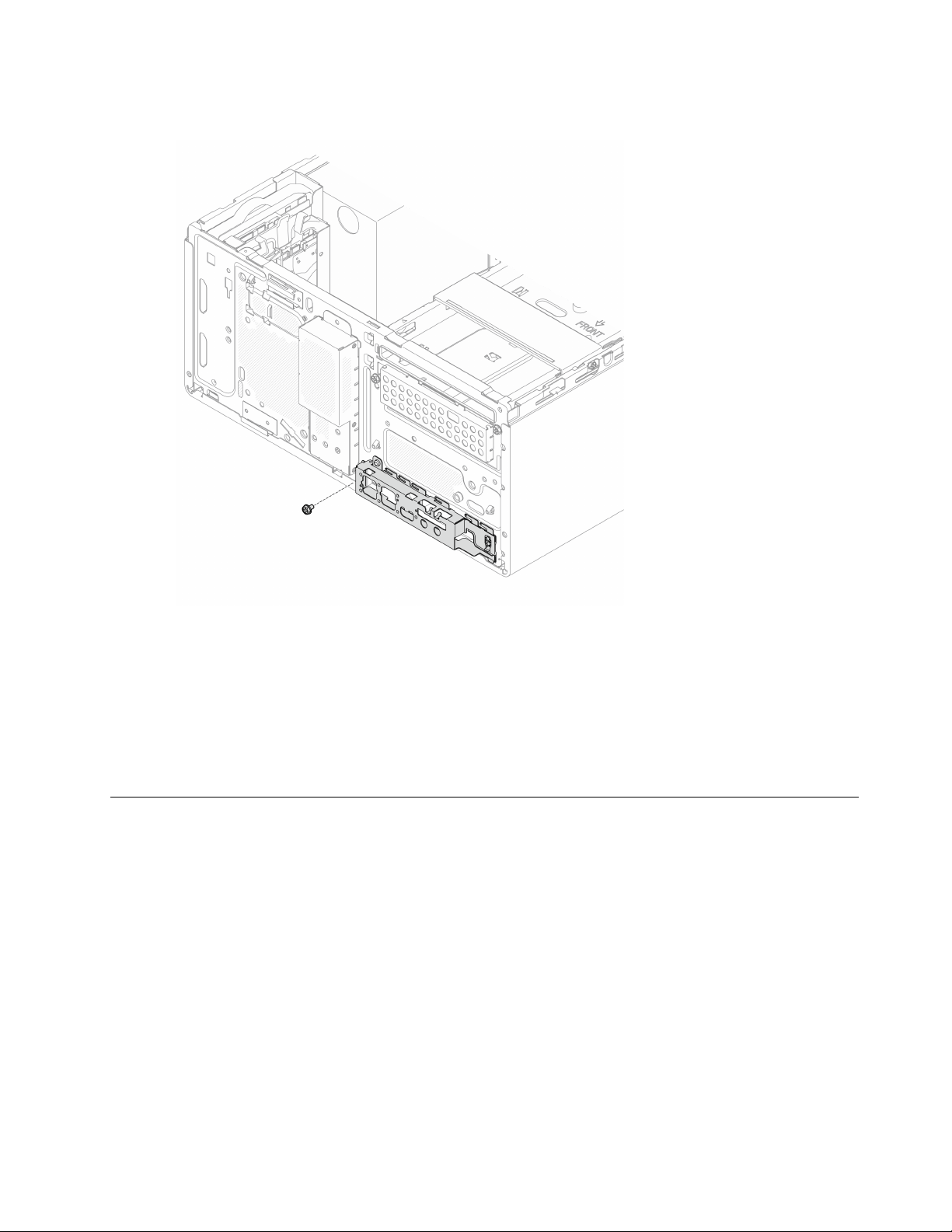
Step 2. Fasten the screw to secure the front panel to the chassis.
Figure 72. Securing front panel to the chassis
Step 3. Connect the power button cable to the system board, see “Internal cable routing” on page 19.
Procedure
1. Reinstall the front bezel, see
“Install the front bezel” on page 86.
2. Proceed to complete the parts replacement, see
“Complete the parts replacement” on page 158.
Heat sink and fan module replacement
Follow this procedure to remove and install the heat sink and fan module.
Remove the heat sink and fan module (trained technician only)
Follow this procedure to remove the heat sink and fan module. This procedure must be executed by a trained
technician.
Chapter 3. Hardware replacement procedures 93
Loading ...
Loading ...
Loading ...