Loading ...
Loading ...
Loading ...
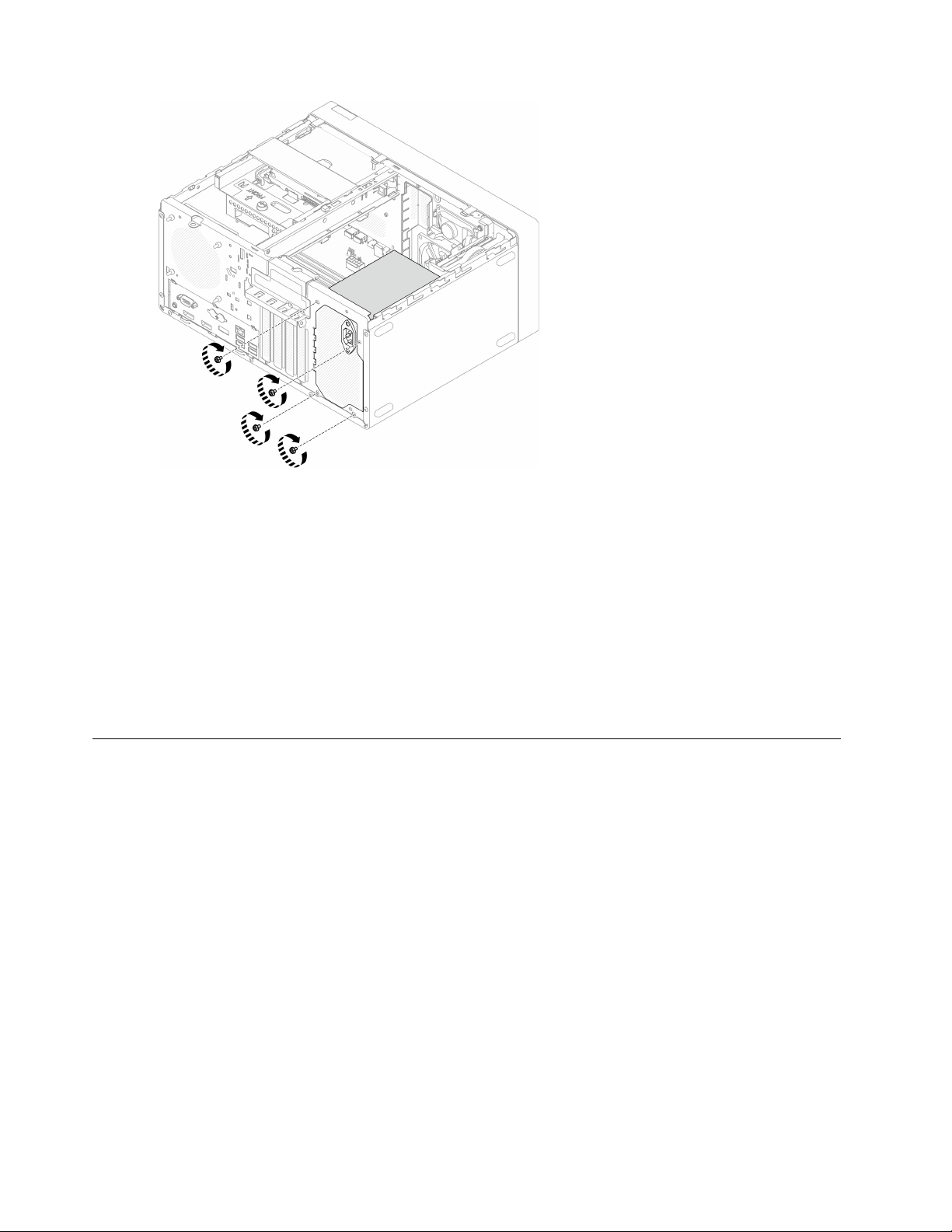
Figure 104. Securing the power supply units to the chassis
Step 3. Connect the processor and system power cables to the system board, see
“Internal cable routing”
on page 19
.
After you finish
1. Reinstall bay 1 drive cage and the 3.5-inch drive, see
“Simple-swap drive and drive cage (bay 1-2)
replacement” on page 50
.
2. If applicable, reinstall bay 2 drive cage and the 2.5-inch drive, see
“Simple-swap drive and drive cage
(bay 1-2) replacement” on page 50
.
3. Proceed to complete the parts replacement, see
“Complete the parts replacement” on page 158.
Processor replacement (trained technician only)
Use the following procedures to remove and install a processor. This procedure must be executed by a
trained technician.
Attention: Before you begin replacing a processor, make sure that you have an alcohol cleaning pad (part
number 00MP352) and gray thermal grease (part number 41Y9292).
Remove the processor (trained technician only)
Follow this procedure to remove the processor. This procedure must be executed by a trained technician.
134
ThinkSystem ST50 V2 Maintenance Manual
Loading ...
Loading ...
Loading ...