
ThinkSystem ST50 V2
Maintenance Manual
Machine Types: 7D8J and 7D8K

Note
Before using this information and the product it supports, be sure to read and understand the safety
information and the safety instructions, which are available at:
http://thinksystem.lenovofiles.com/help/topic/
safety_documentation/pdf_files.html
In addition, ensure that you are familiar with the terms and conditions of the Lenovo warranty for your server,
which can be found at:
http://datacentersupport.lenovo.com/warrantylookup
First Edition (March 2022)
© Copyright Lenovo 2022, 2022.
LIMITED AND RESTRICTED RIGHTS NOTICE: If data or software is delivered pursuant to a General Services
Administration (GSA) contract, use, reproduction, or disclosure is subject to restrictions set forth in Contract No.
GS-35F-05925.

Contents
Contents . . . . . . . . . . . . . . . . . i
Safety . . . . . . . . . . . . . . . . . . iii
Safety inspection checklist . . . . . . . . . . . iv
Chapter 1. Introduction . . . . . . . . . 1
Server form factor . . . . . . . . . . . . . . . 2
Specifications . . . . . . . . . . . . . . . . 2
Particulate contamination . . . . . . . . . . 7
Update the firmware . . . . . . . . . . . . . . 8
Tech Tips . . . . . . . . . . . . . . . . . . 9
Security advisories . . . . . . . . . . . . . . 9
Power on the server . . . . . . . . . . . . . . 9
Power off the server . . . . . . . . . . . . . . 9
Chapter 2. Server components . . . . 11
Front view . . . . . . . . . . . . . . . . . 11
Front panel . . . . . . . . . . . . . . . . 11
Side view . . . . . . . . . . . . . . . . . 13
Rear view . . . . . . . . . . . . . . . . . 14
Server locks . . . . . . . . . . . . . . . . 17
System board components . . . . . . . . . . 18
RAID adapters . . . . . . . . . . . . . . . 19
Internal cable routing. . . . . . . . . . . . . 19
Cable routing for drive bay 1 and bay 2 . . . . 21
Cable routing for drive bay 3 . . . . . . . . 23
Cable routing for optical disk drive. . . . . . 24
Cable routing for the RAID adapter and
drives . . . . . . . . . . . . . . . . . 25
Cable routing for the power supply unit . . . . 28
Cable routing for the front fan and rear fan . . 29
Cable routing for the heat sink and fan
module . . . . . . . . . . . . . . . . 30
Cable routing for the intrusion switch. . . . . 32
Cable routing for the thermal sensor . . . . . 33
Cable routing for the mono amplifier . . . . . 34
Cable routing for the power button with
LED. . . . . . . . . . . . . . . . . . 35
Parts list. . . . . . . . . . . . . . . . . . 36
Power cords . . . . . . . . . . . . . . 39
Chapter 3. Hardware replacement
procedures . . . . . . . . . . . . . . . 41
Installation guidelines . . . . . . . . . . . . 41
System reliability guidelines . . . . . . . . 42
Handling static-sensitive devices . . . . . . 43
Memory module installation rules . . . . . . . . 44
CMOS battery (CR2032) replacement . . . . . . 45
Remove the CMOS battery (CR2032) . . . . 45
Install the CMOS battery (CR2032) . . . . . 47
Drive and drive cage replacement. . . . . . . . 49
Drive bay locations. . . . . . . . . . . . 49
Simple-swap drive and drive cage (bay 1-2)
replacement . . . . . . . . . . . . . . 50
Simple-swap drive and drive cage
replacement (bay 3) . . . . . . . . . . . 62
Optical drive and drive cage replacement . . . 70
Fan replacement . . . . . . . . . . . . . . 80
Remove the fan (front and rear) . . . . . . . 80
Install the fan (front and rear) . . . . . . . . 82
Front bezel replacement . . . . . . . . . . . 84
Remove the front bezel . . . . . . . . . . 84
Install the front bezel . . . . . . . . . . . 86
Front panel replacement . . . . . . . . . . . 87
Remove the front panel . . . . . . . . . . 87
Install the front panel . . . . . . . . . . . 91
Heat sink and fan module replacement. . . . . . 93
Remove the heat sink and fan module (trained
technician only) . . . . . . . . . . . . . 93
Install the heat sink and the fan module
(trained technician only) . . . . . . . . . . 97
Intrusion switch replacement . . . . . . . . . 100
Remove the intrusion switch . . . . . . . . 100
Install the intrusion switch . . . . . . . . . 102
M.2 drive and retainer replacement . . . . . . . 104
Remove an M.2 drive . . . . . . . . . . . 104
Install an M.2 drive . . . . . . . . . . . . 106
Remove the M.2 drive retainer . . . . . . . 107
Install the M.2 drive retainer . . . . . . . . 110
Memory module replacement . . . . . . . . . 112
Remove a memory module . . . . . . . . 112
Install a memory module . . . . . . . . . 113
Mono amplifier (speaker) replacement . . . . . . 116
Remove the mono amplifier (speaker) . . . . 116
Install the mono amplifier (speaker) . . . . . 119
PCIe adapter replacement. . . . . . . . . . . 120
Remove a PCIe adapter . . . . . . . . . . 120
Install a PCIe adapter . . . . . . . . . . . 123
Power button with LED replacement. . . . . . . 126
Remove the power button with LED . . . . . 126
Install the power button with LED . . . . . . 128
Power supply unit replacement. . . . . . . . . 129
Remove the power supply unit . . . . . . . 129
Install the power supply unit . . . . . . . . 132
© Copyright Lenovo 2022, 2022 i

Processor replacement (trained technician
only) . . . . . . . . . . . . . . . . . . . 134
Remove the processor (trained technician
only) . . . . . . . . . . . . . . . . . 134
Install the processor (trained technician
only) . . . . . . . . . . . . . . . . . 136
Server replacement . . . . . . . . . . . . . 138
Remove the server from the rails . . . . . . 138
Install the server to the rails . . . . . . . . 140
Server cover replacement . . . . . . . . . . . 144
Remove the server cover . . . . . . . . . 144
Install the server cover . . . . . . . . . . 147
System board replacement (trained technician
only) . . . . . . . . . . . . . . . . . . . 149
Remove the system board (trained technician
only) . . . . . . . . . . . . . . . . . 149
Install the system board (trained technician
only) . . . . . . . . . . . . . . . . . 151
Thermal sensor replacement . . . . . . . . . . 154
Remove the thermal sensor . . . . . . . . 154
Install the thermal sensor . . . . . . . . . 156
Complete the parts replacement . . . . . . . . 158
Chapter 4. Problem
determination . . . . . . . . . . . . . 159
Event logs . . . . . . . . . . . . . . . . . 159
General problem determination procedures . . . . 159
List of POST error messages . . . . . . . . 160
Resolving suspected power problems . . . . 163
Resolving suspected Ethernet controller
problems . . . . . . . . . . . . . . . 163
Troubleshooting by symptom . . . . . . . . . 164
Power on and power off problems . . . . . . 164
Memory problems . . . . . . . . . . . . 165
Hard disk drive problems . . . . . . . . . 166
Monitor and video problems . . . . . . . . 167
Optional-device problems . . . . . . . . . 168
Intermittent problems. . . . . . . . . . . 169
Network problems . . . . . . . . . . . . 170
Observable problems. . . . . . . . . . . 171
Software problems. . . . . . . . . . . . 172
Chapter 5. Hardware disassembling
for recycle . . . . . . . . . . . . . . . 175
Disassemble the server for chassis recycle . . . . 175
Appendix A. Getting help and
technical assistance . . . . . . . . . . 177
Before you call . . . . . . . . . . . . . . . 177
Contacting Support . . . . . . . . . . . . . 178
Appendix B. Notices. . . . . . . . . . 179
Trademarks . . . . . . . . . . . . . . . . 180
Important notes . . . . . . . . . . . . . . . 180
Telecommunication regulatory statement. . . . . 180
Electronic emission notices . . . . . . . . . . 181
Taiwan BSMI RoHS declaration . . . . . . . 181
Taiwan import and export contact information . . . 181
ii ThinkSystem ST50 V2 Maintenance Manual
Safety
Before installing this product, read the Safety Information.
Antes de instalar este produto, leia as Informações de Segurança.
在安装本产品之前,请仔细阅读 Safety Information (安全信息)。
Læs sikkerhedsforskrifterne, før du installerer dette produkt.
Lees voordat u dit product installeert eerst de veiligheidsvoorschriften.
Ennen kuin asennat tämän tuotteen, lue turvaohjeet kohdasta Safety Information.
Avant d'installer ce produit, lisez les consignes de sécurité.
Vor der Installation dieses Produkts die Sicherheitshinweise lesen.
Prima di installare questo prodotto, leggere le Informazioni sulla Sicurezza.
Les sikkerhetsinformasjonen (Safety Information) før du installerer dette produktet.
Antes de instalar este produto, leia as Informações sobre Segurança.
© Copyright Lenovo 2022, 2022 iii
Antes de instalar este producto, lea la información de seguridad.
Läs säkerhetsinformationen innan du installerar den här produkten.
Safety inspection checklist
Use the information in this section to identify potentially unsafe conditions with your server. As each machine
was designed and built, required safety items were installed to protect users and service technicians from
injury.
Note: This device is not intended for use in the direct field of view at visual display workplaces. To avoid
incommoding reflections at visual display workplaces, this device must not be placed in the direct field of
view.
Attention: This is a Class A product. In a domestic environment, this product may cause radio interference
in which case the user may be required to take adequate measures.
CAUTION:
This equipment must be installed or serviced by trained personnel, as defined by the NEC, IEC 62368-
1 & IEC 60950-1, the standard for Safety of Electronic Equipment within the Field of Audio/Video,
Information Technology and Communication Technology. Lenovo assumes you are qualified in the
servicing of equipment and trained in recognizing hazards energy levels in products.
Important: Electrical grounding of the server is required for operator safety and correct system function.
Proper grounding of the electrical outlet can be verified by a certified electrician.
Use the following checklist to verify that there are no potentially unsafe conditions:
1. Make sure that the power is off and the power cord is disconnected.
2. Check the power cord.
• Make sure that the third-wire ground connector is in good condition. Use a meter to measure third-
wire ground continuity for 0.1 ohm or less between the external ground pin and the frame ground.
• Make sure that the power cord is the correct type.
To view the power cords that are available for the server:
a. Go to:
http://dcsc.lenovo.com/#/
b. Click Preconfigured Model or Configure to order.
c. Enter the machine type and model for your server to display the configurator page.
iv ThinkSystem ST50 V2 Maintenance Manual

d. Click Power ➙ Power Cables to see all line cords.
• Make sure that the insulation is not frayed or worn.
3. Check for any obvious non-Lenovo alterations. Use good judgment as to the safety of any non-Lenovo
alterations.
4. Check inside the server for any obvious unsafe conditions, such as metal filings, contamination, water or
other liquid, or signs of fire or smoke damage.
5. Check for worn, frayed, or pinched cables.
6. Make sure that the power-supply cover fasteners (screws or rivets) have not been removed or tampered
with.
© Copyright Lenovo 2022, 2022 v

vi ThinkSystem ST50 V2 Maintenance Manual
Chapter 1. Introduction
The ThinkSystem ST50 V2 server is a 4U tower server designed for performance and expansion for various IT
workloads. With the modular design, the server is flexible to be customized for maximum storage capacity or
high storage density with selectable input/output options and tiered system management.
Performance, ease of use, reliability, and expansion capabilities were key considerations in the design of the
server. These design features make it possible for you to customize the system hardware to meet your needs
today and provide flexible expansion capabilities for the future.
The server comes with a limited warranty. For details about the warranty, see:
https://support.lenovo.com/us/
en/solutions/ht503310
For details about your specific warranty, see:http://datacentersupport.lenovo.com/warrantylookup
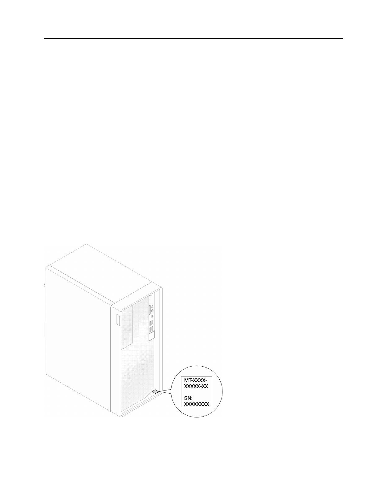
Identifying your server
When you contact Lenovo for help, the machine type and serial number information helps support
technicians to identify your server and provide faster service.
The machine type and serial number are on the ID label on the front of the server.
The following illustration shows the location of the ID label.
Note: The illustrations in this document might differ slightly from your server.
Figure 1. Location of the ID label
© Copyright Lenovo 2022, 2022 1
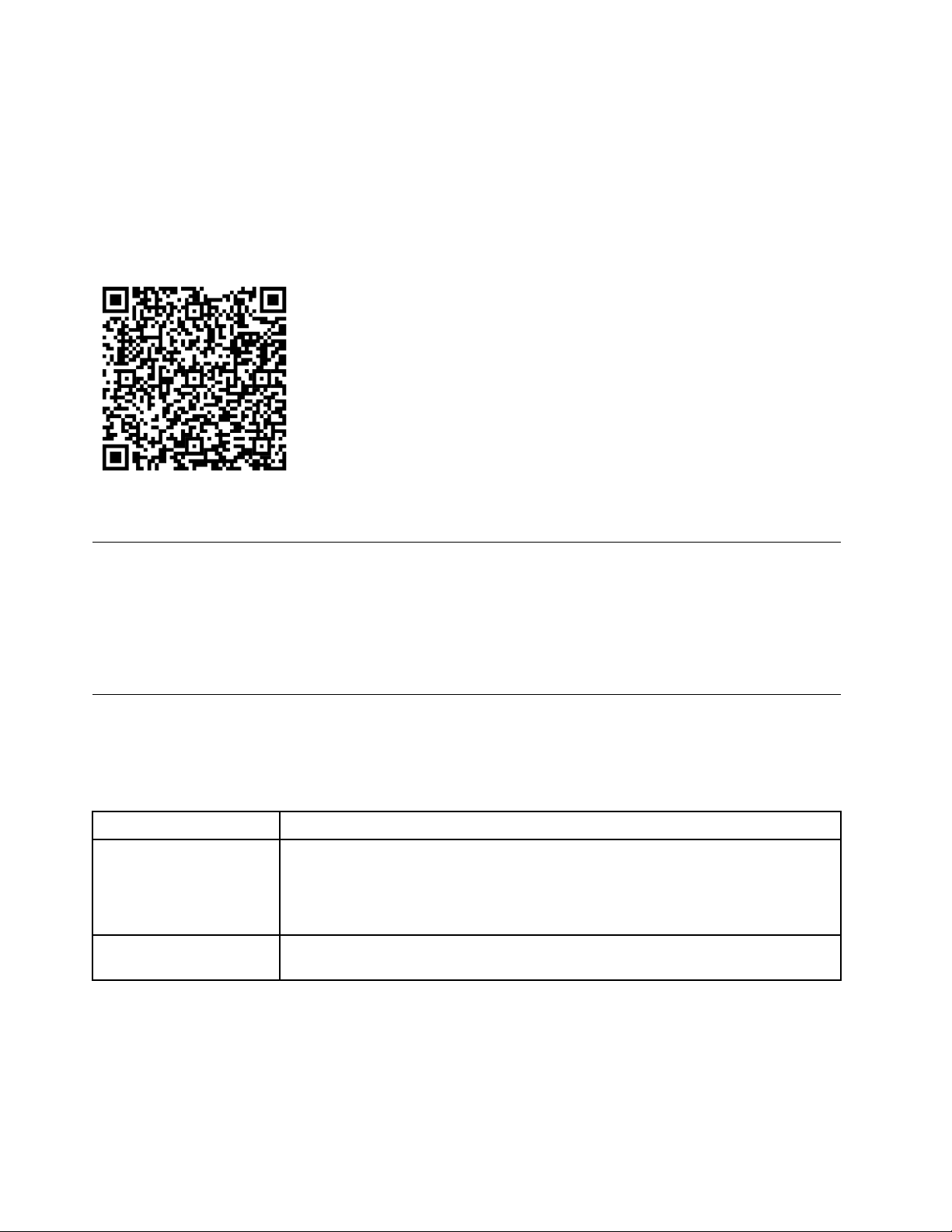
Quick response code
The system service label, which is on the inside of the server cover, provides a quick response (QR) code for
mobile access to service information. Scan the QR code with a mobile device and a QR code reader
application to get quick access to the Lenovo Service web site for this server. The Lenovo Service web site
provides additional information for parts installation and replacement videos, and error codes for server
support.
The following illustration shows the QR code.
Figure 2. QR code
Server form factor
The ThinkSystem ST50 V2 server is designed to support both tower and rack form factors.
You can change the server from tower form factor to rack form factor by installing the tower-to-rack
conversion kit. For instructions on how to install the tower-to-rack conversion kit, refer to the documentation
that comes with the conversion kit.
Specifications
The following information is a summary of the features and specifications of the server. Depending on the
model, some features might not be available, or some specifications might not apply.
Table 1. Specifications, Type 7D8J and 7D8K
Specification Description
Dimension 4U server
• Width: 170 mm (6.7 inches)
• Height: 376 mm (14.8 inches)
– Height without stands: 370 mm (14.6 inches)
• Depth: 315.4 mm (12.4 inches)
Weight (depending on the
configuration)
• Maximum: 9.4 kg (20.7 lb)
2 ThinkSystem ST50 V2 Maintenance Manual
Table 1. Specifications, Type 7D8J and 7D8K (continued)
Specification
Description
Processor This server supports one of the following Intel
®
processors:
• Xeon
®
E3–23XX
• Pentium Gold
For a list of supported processors, see
https://static.lenovo.com/us/en/serverproven/
index.shtml
.
Note:
Xeon
®
E3–23XX processor without integrated graphics feature does not support the
KVM redirection functions; GPU is required when such processor is installed. If a
processor with integrated graphics feature and a GPU are installed in the system, the
integrated graphics feature and the DisplayPorts will be disabled.
Memory • Slots: four DIMM slots (two channels, two DIMMs per channel)
• Minimum capacity: 8 GB
• Maximum capacity: 64 GB
• DIMM types:
– 8GB 1Rx8 3200MT/s ECC UDIMM
– 16GB 2Rx8 3200MT/s ECC UDIMM
Note: Pentium processor supports up to 2666 MT/s.
For more information on memory module installation rules and supported memory
speed, see
“Memory module installation rules” on page 44.
Storage expansion Two 3.5-inch drive bays (one for optional), one 2.5-inch drive bay (optional), one ODD
bay, and one M.2 drive.
• Drive bay 1
– 3.5-inch hard-disk drive or solid-state drive
• Drive bay 2 (Optional)
– One 2.5-inch hard-disk drive or solid-state drive
• Drive bay 3 (Optional)
– One 3.5-inch hard-disk drive or solid-state drive
• ODD drive bay (Optional)
– One 9mm slim SATA Optical disk drive
• M.2 drive (Optional)
– One 2280 NVMe PCIe standard M.2 module (for booting)
Expansion slots Three PCIe expansion slots are available:
• PCIe slot 1: PCI Express 4.0 x16 (FHHL 75W PCIe adapter)
• PCIe slot 2: PCI Express 3.0 x1 (FHHL, 25W PCIe adapter)
• PCIe slot 3: PCI Express 3.0 x4 in x16 slot (FHHL, 25W PCIe adapter)
Notes:
• Pentium processor supports up to PCI Express 3.0.
• When installing PCIe x8/x16 adapter to PCIe Slot 3, the PCIe adapter performance
might be degraded due to the bandwidth of PCIe slot 3 (x4).
• For PXE boot application (Preboot eXecution Environment), it is recommended to
install a PXE boot supporting Ethernet adapter for best performance.
One M.2 expansion slot is available
• One 2280 NVMe PCIe standard M.2 module (for booting) (Optional)
Chapter 1. Introduction 3
Table 1. Specifications, Type 7D8J and 7D8K (continued)
Specification
Description
Integrated functions The server supports nine universal serial bus (USB) connectors
• On the front of the server
– One USB 3.2 Gen 1 Type C port
– Two USB 3.2 Gen 1 ports
– Two USB 3.2 Gen 2 ports
• On the rear of the server
– Four USB 3.2 Gen 1 ports
Notes:
• USB 3.2 Gen 1: 5 Gbps = 640 MB/s
• USB 3.2 Gen 2: 10 Gbps = 1280 MB/s
Connectors and button on the front of the server
• Power button with LED
• One Mic-in connector*
• One combo audio jack connector*
Connectors and port on the rear of the server
• One 1 GbE RJ-45 Ethernet connector with Intel I219-LM
• Two DisplayPort connectors (4K/ 60MHz)
†
• One serial connector
• One audio line-out port*
Note:
* Supported by Windows Client OS only.
† Supported by processor with integrated graphic feature only. See the “Processor”
section at
“Specifications” on page 2 for more information.
Network
• One 1 GbE RJ-45 Ethernet connector with Intel I219-LM. See
“Rear view” on page
14
.
• Supports up to two network adapters.
Note:
For PXE boot application (Preboot eXecution Environment), it is recommended to install
a PXE boot supporting Ethernet adapter for best performance.
For a list of supported network adapters, see
https://static.lenovo.com/us/en/
serverproven/index.shtml
.
4 ThinkSystem ST50 V2 Maintenance Manual
Table 1. Specifications, Type 7D8J and 7D8K (continued)
Specification
Description
Systems management
• Intel
®
Active Management Technology (AMT) 15.0
• Lenovo XClarity Provisioning Manager Lite (optional).
• TPM 2.0 embedded
Notes:
• Make sure the power is on when executing remote access and power policy setup.
• Ignore the warning message “Unrecoverable PS/2 or USB keyboard failure,” because
the system does not support PS/2 devices.
• Some Lenovo systems management applications, including XClarity Administrator,
XClarity Controller, XClarity Energy Manager, and XClarity Essentials, are not
supported by ST50 V2.
• For information on the Lenovo XClarity Provisioning Manager Lite, see the LXPM
documentation compatible with your server at
https://sysmgt.lenovofiles.com/help/
topic/lxpm_frontend/lxpm_product_page.html
.
RAID (depending on model) Software RAID
Onboard 6 Gb SATA controller that supports AHCI mode (JBOD) or RSTe mode (RAID).
RSTe mode supports RAID 0, 1 and 5.
Hardware RAID
The server supports RAID level 0 and 1.
The RAID adapter should be installed in PCIe slot 1.
The following RAID adapter options are available for this server:
• ThinkSystem 4350-8i SAS/SATA 12Gb HBA
• ThinkSystem RAID 5350-8i PCIe 12Gb Adapter
For a list of supported adapters, see:
https://static.lenovo.com/us/en/serverproven/
index.shtml
.
Note:
Hard-disk drives or solid-state drives can be installed in the same server but are not
supported in the same RAID array.
Graphics processing unit
(GPU) adapter
The following option GPU adapter is available for this server:
• ThinkSystem NVIDIA Quadro T1000 8GB PCIe Active GPU
– Must be installed in PCIe expansion slot 1
– This GPU adapter supports 8K resolution.
– It is recommend to use certified display adapter cables.
Fans This server supports up to three fans:
• When processor TDP is lower than 95 watts
– One front fan
– One rear fan (only when drive bay 3 is installed)
– One processor heat sink fan
• When processor TDP is 95 watts
– One front fan
– One processor heat sink fan
Chapter 1. Introduction 5
Table 1. Specifications, Type 7D8J and 7D8K (continued)
Specification
Description
Electrical input This server supports one of the following non-hot-swap, non-redundant power supplies:
• Fixed ATX 300 watt Single-Output Gold
– Input power 115Vac or 230Vac
This power supply does not support Intel Xeon
®
E3–2388G and E3–2378.
• Fixed ATX 500 watt Multi-Output Platinum
– Input power 115Vac or 230Vac
Minimal configuration for
debugging
• One processor
• One 8 GB ECC UDIMM in slot 1
• One power supply
• One 3.5-inch drive in drive bay 1
• Power cord
• One system front fan
Acoustical noise emissions
• Sound power level (L
WAd):
– Idling
– Typical: 3.5 Bel
– Maximum: 5.0 Bel
– Operating
– Typical: 5.4 Bel
– Maximum: 5.4 Bel
• Sound pressure level (L
pAm):
– Idling
– Typical: 25 dBA
– Maximum: 37 dBA
– Operating
– Typical: 40 dBA
– Maximum: 40 dBA
Notes:
1. These sound levels were measured in controlled acoustical environments according
to procedures specified by ISO 7779 and are reported in accordance with ISO
9296.
2. The declared acoustic sound levels are based on the following configurations,
which may change depending on configuration/conditions:
• Typical: 1x 80W CPU, 4x 32GB DIMM, 2x HDD or SSD, 1x 960G M.2, RAID
5350-8i, 1x 300W PSU
• Maximum: 1x 95W CPU, 4x 32GB DIMM, 2x HDD or SSD, 1x 960G M.2, 1x
T1000GPU, 1x 500W PSU
Heat output Approximate heat output:
• Minimum configuration: 443 BTU, 130 W (in BTU per hour and watts)
• Maximum configuration: 754 BTU, 221 W (in BTU per hour and watts)
6 ThinkSystem ST50 V2 Maintenance Manual
Table 1. Specifications, Type 7D8J and 7D8K (continued)
Specification
Description
Environment
ThinkSystem ST50 V2 complies with ASHRAE Class A2 specifications.
• Air temperature:
– Operating
– ASHRAE Class A2: 10°C to 35°C (50°F to 95°F); the maximum ambient
temperature decreases by 1°C for every 300 m (984 ft) increase in altitude
above 900 m (2,953 ft).
– Server off: -10°C to 60°C (14°F to 140°F)
– Shipment/storage: -20°C to 60°C (-4°F to 140°F)
• Maximum altitude: 3,050 m (10,000 ft)
• Relative Humidity (non-condensing):
– Operating
– ASHRAE Class A2: 8% to 80%; maximum dew point: 21°C (70°F)
– Shipment/storage: 8% to 90%
• Particulate contamination
Attention: Airborne particulates and reactive gases acting alone or in combination
with other environmental factors such as humidity or temperature might pose a risk to
the server. For information about the limits for particulates and gases, see
“Particulate contamination” on page 7.
Operating systems Supported and certified operating systems:
• Microsoft Windows Server
• VMware ESXi
• Red Hat Enterprise Linux
• SUSE Linux Enterprise Server
• Ubuntu
References:
• Complete list of available operating systems:
https://lenovopress.com/osig.
• OS deployment instructions: See “Deploy the operating system” in Setup Guide.
Particulate contamination
Attention: Airborne particulates (including metal flakes or particles) and reactive gases acting alone or in
combination with other environmental factors such as humidity or temperature might pose a risk to the
device that is described in this document.
Risks that are posed by the presence of excessive particulate levels or concentrations of harmful gases
include damage that might cause the device to malfunction or cease functioning altogether. This
specification sets forth limits for particulates and gases that are intended to avoid such damage. The limits
must not be viewed or used as definitive limits, because numerous other factors, such as temperature or
moisture content of the air, can influence the impact of particulates or environmental corrosives and gaseous
contaminant transfer. In the absence of specific limits that are set forth in this document, you must
implement practices that maintain particulate and gas levels that are consistent with the protection of human
health and safety. If Lenovo determines that the levels of particulates or gases in your environment have
caused damage to the device, Lenovo may condition provision of repair or replacement of devices or parts
on implementation of appropriate remedial measures to mitigate such environmental contamination.
Implementation of such remedial measures is a customer responsibility.
Chapter 1. Introduction 7
Table 2. Limits for particulates and gases
Contaminant Limits
Reactive gases
Severity level G1 as per ANSI/ISA 71.04-1985
1
:
• The copper reactivity level shall be less than 300 Angstroms per month (Å/month ≈ 0.0039 μg/
cm
2
-hour weight gain).
2
• The silver reactivity level shall be less than 200 Å/month (Å/month ≈ 0.0035 μg/cm
2
-hour
weight gain).
3
• The reactive monitoring of gaseous corrosivity must be conducted approximately 5 cm (2 in.) in
front of the rack on the air inlet side at one-quarter and three-quarter frame height off the floor
or where the air velocity is much higher.
Airborne
particulates
Data centers must meet the cleanliness level of ISO 14644-1 class 8.
For data centers without airside economizer, the ISO 14644-1 class 8 cleanliness might be met by
choosing one of the following filtration methods:
• The room air might be continuously filtered with MERV 8 filters.
• Air entering a data center might be filtered with MERV 11 or preferably MERV 13 filters.
For data centers with airside economizers, the choice of filters to achieve ISO class 8 cleanliness
depends on the specific conditions present at that data center.
• The deliquescent relative humidity of the particulate contamination should be more than 60%
RH.
4
• Data centers must be free of zinc whiskers.
5
1
ANSI/ISA-71.04-1985. Environmental conditions for process measurement and control systems: Airborne
contaminants. Instrument Society of America, Research Triangle Park, North Carolina, U.S.A.
2
The derivation of the equivalence between the rate of copper corrosion growth in the thickness of the corrosion
product in Å/month and the rate of weight gain assumes that Cu2S and Cu2O grow in equal proportions.
3
The derivation of the equivalence between the rate of silver corrosion growth in the thickness of the corrosion
product in Å/month and the rate of weight gain assumes that Ag
2S is the only corrosion product.
4
The deliquescent relative humidity of particulate contamination is the relative humidity at which the dust absorbs
enough water to become wet and promote ionic conduction.
5
Surface debris is randomly collected from 10 areas of the data center on a 1.5 cm diameter disk of sticky
electrically conductive tape on a metal stub. If examination of the sticky tape in a scanning electron microscope
reveals no zinc whiskers, the data center is considered free of zinc whiskers.
Update the firmware
Go to Lenovo Datacenter Support site for the latest firmware update package.
To update the firmware from a flash device, complete the following steps:
1. Go to
https://datacentersupport.lenovo.com/tw/en/products/servers/thinksystem/st50v2/downloads/driver-
list/
. All the downloadable firmware packages for ST50 V2 are available on this site.
2. Download the latest version of firmware update packages.
3. Follow the instructions enclosed in the package to update the firmware.
Note: Perform the firmware update in operating system accordingly to the instructions.
8
ThinkSystem ST50 V2 Maintenance Manual
Tech Tips
Lenovo continually updates the support website with the latest tips and techniques that you can use to solve
issues that your server might encounter. These Tech Tips (also called retain tips or service bulletins) provide
procedures to work around issues or solve problems related to the operation of your server.
To find the Tech Tips available for your server:
1. Go to
http://datacentersupport.lenovo.com and navigate to the support page for your server.
2. Click on the documentation icon
from the navigation pane.
3. Click Documentation Type ➙ Solution from the drop-down menu.
Follow the on-screen instructions to choose the category for the problem that you are having.
Security advisories
Lenovo is committed to developing products and services that adhere to the highest security standards in
order to protect our customers and their data. When potential vulnerabilities are reported, it is the
responsibility of the Lenovo Product Security Incident Response Team (PSIRT) to investigate and provide
information to our customers so they may put mitigation plans in place as we work toward providing
solutions.
The list of current advisories is available at the following location:
https://datacentersupport.lenovo.com/
product_security/home
Power on the server
The server can be turned on (power LED on) in any of the following ways:
• Press the power button. Before the operating system starts running, you can press Enter to enter Startup
Interrupt Menu. In this menu, a few options are available for various purposes:
– Press Esc to resume to normal startup.
– Press F1 to enter the Setup Utility.
– Press F10 to diagnose hardware.
– Press F11 to choose a temporary startup device.
– Press Ctrl + P to enter the Management Engine setup screen or initiate a remote connection.
– Press Enter to pause.
• The server can restart automatically after a power interruption.
Note: If the boot screen lingers with the message of “System Security - The system has been tempered
with,” it means the server cover is not properly installed. Remove and reinstall it (see
“Server cover
replacement” on page 144
); then, restart the server.
For information about powering off the server, see
“Power off the server” on page 9.
Power off the server
The server remains in a standby state when it is connected to a power source. To remove all power from the
server (power-on LED off), you must disconnect all power cables.
To place the server in a standby state (power-on LED flashes once per second):
Chapter 1. Introduction 9

• Start an orderly shutdown using the operating system (if supported by your operating system).
• Press the power-on button to start an orderly shutdown (if supported by your operating system).
• Press and hold the power button for more than 4 seconds to force a shutdown.
10
ThinkSystem ST50 V2 Maintenance Manual
Chapter 2. Server components
This section provides information that helps locate the server components.
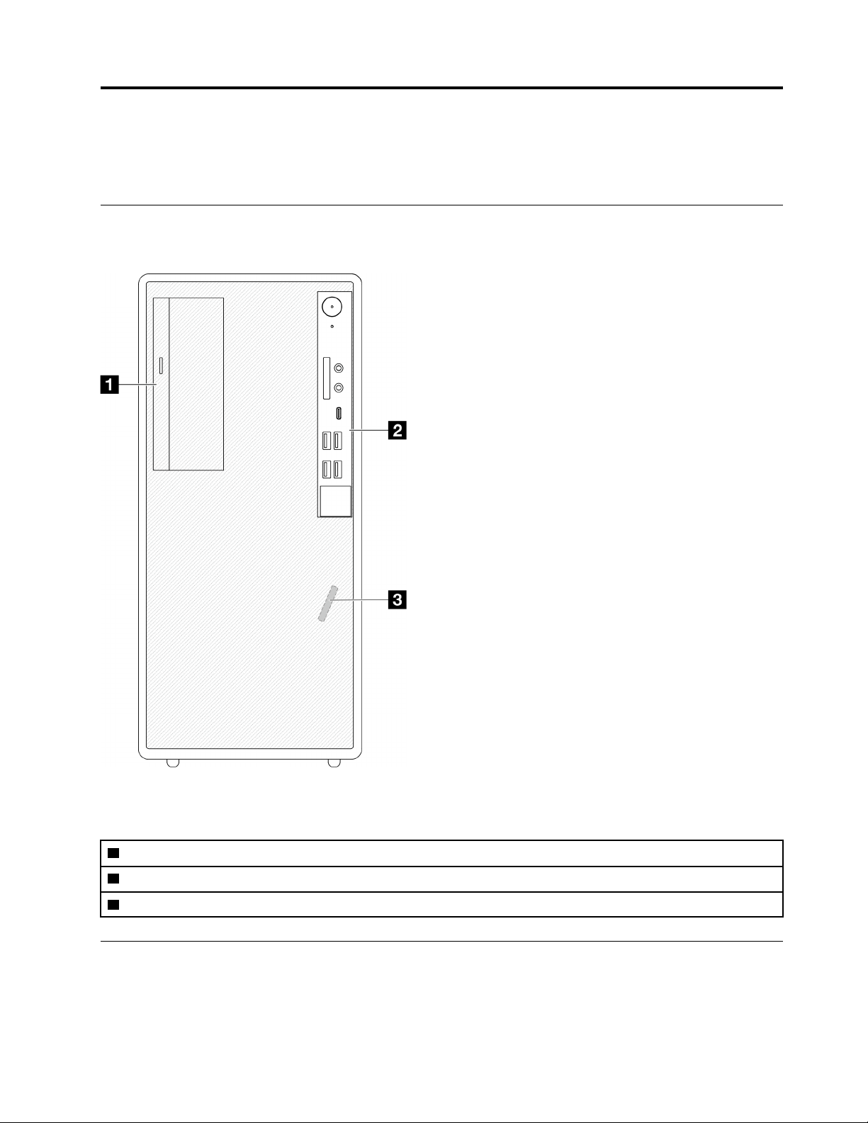
Front view
Read this section to identify important components on the front of this server.
Figure 3. Front view
Table 3. Front view
1 Slim SATA optical disk drive (optional)
2 Front panel. See “Front panel” on page 11 for more information.
3 Front thermal sensor
Front panel
Some crucial key controls, connectors, and LEDs are located on the front panel of the server.
The following illustration shows the controls, connectors, and LEDs on the front panel of the server.
© Copyright Lenovo 2022, 2022 11
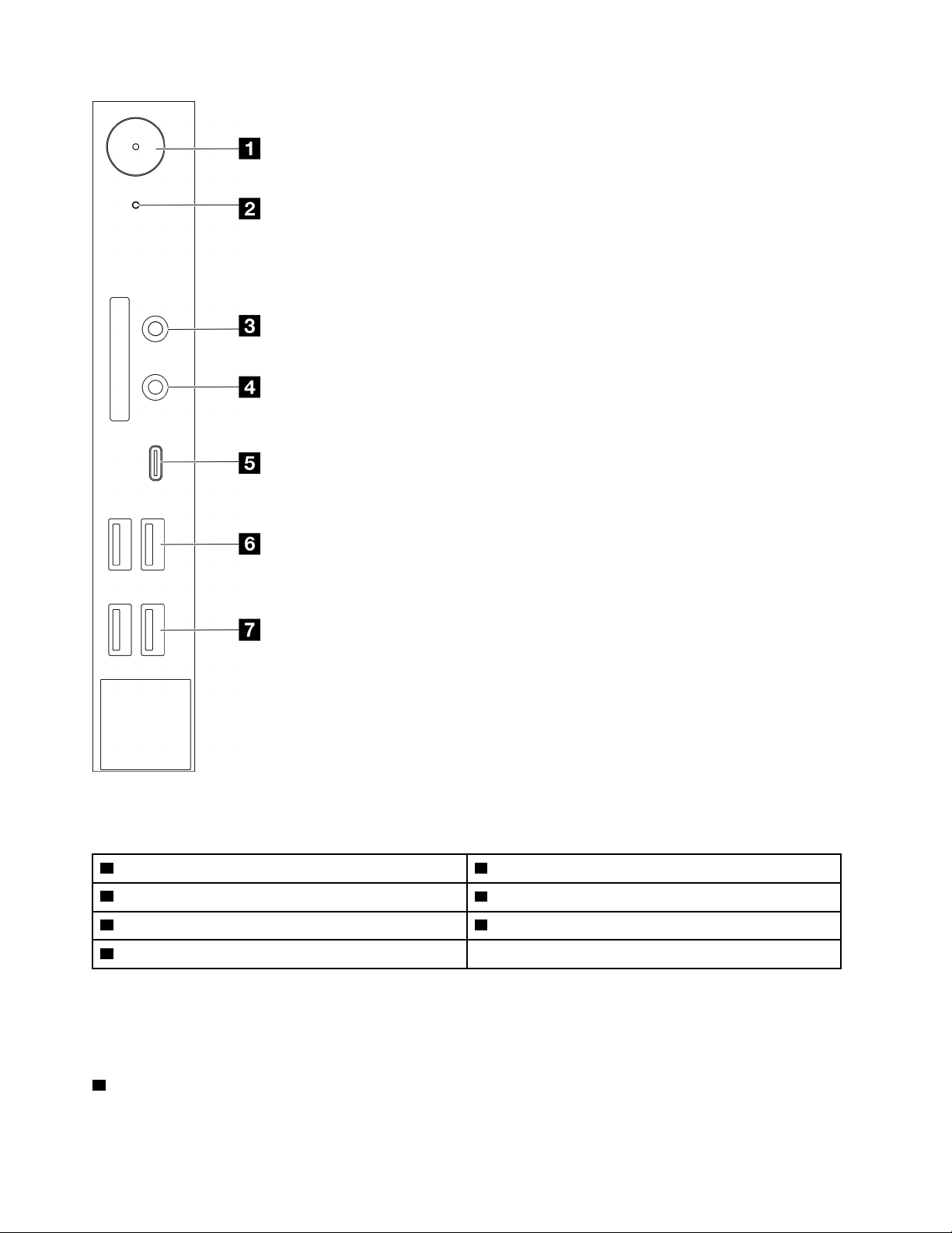
Figure 4. Components on the front panel
Table 4. Components on the front panel
1 Power button with power status (white) 5 USB Type-C 3.2 Gen2 connector
2 Drive activity LED (white) 6 Two USB 3.1 Gen1 connectors
3 Mic-in connector (Windows Client OS only) 7 Two USB 3.2 Gen 2 connectors
4 Headset connector (Windows Client OS only)
Notes:
• USB 3.2 Gen 1: 5 Gbps = 640 MB/s
• USB 3.2 Gen 2: 10 Gbps = 1280 MB/s
1 Power button with power status LED (white)
12
ThinkSystem ST50 V2 Maintenance Manual
Press the power button to turn on the server, or hold it for several seconds to turn the server off when the
server cannot be turned off in the operating system. The power status LED helps determine the current
power status.
Table 5. Power button LED behavior
Status Color Description
Solid on
White
DC power is present and the server is on.
Off
None
No DC power is present and the server is off.
2 Drive activity LED (white)
This LED indicates the activity of the drives.
Note: The drive activity LED only indicates the activities of drives that are connected to the SATA ports on
the system board.
Table 6. Drive activity LED behavior
Status Color Description
Solid on
White The drives are active.
Off
None The drives are not active.
3 Mic-in connector
Plug in microphone to this connector.
Note: This connector is only supported by Windows Client OS.
4 Headset connector
Plug in headset with microphone to this connector. A standard headphone or microphone can also be
plugged into the connector.
Note: This connector is only supported by Windows Client OS.
5 USB Type-C 3.2 Gen2 connector
One USB Type-C 3.2 Gen2 connector on the front panel that is available for a device that require USB 2.0 or
3.0 connection, such as a keyboard, a mouse, or a USB flash drive.
6 Two USB 3.1 Gen1 connectors
There are two USB 3.1 Gen1 connectors on the front panel. These connectors are available for a device that
require USB 3.0 connection, such as a keyboard, a mouse, or a USB flash drive.
7 Two USB 3.1 Gen2 connectors
There are two USB 3.1 Gen2 connectors on the front panel. These connectors are available for a device that
require USB 3.0 connection, such as a keyboard, a mouse, or a USB flash drive.
Side view
See this topic to learn about the components visible from the side of the server.
Chapter 2. Server components 13
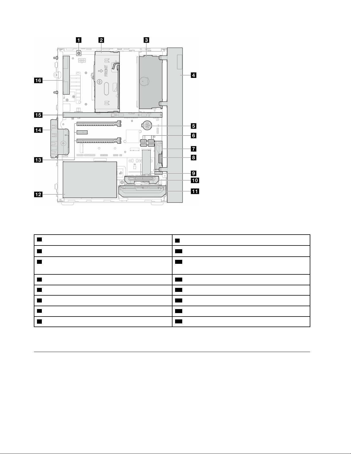
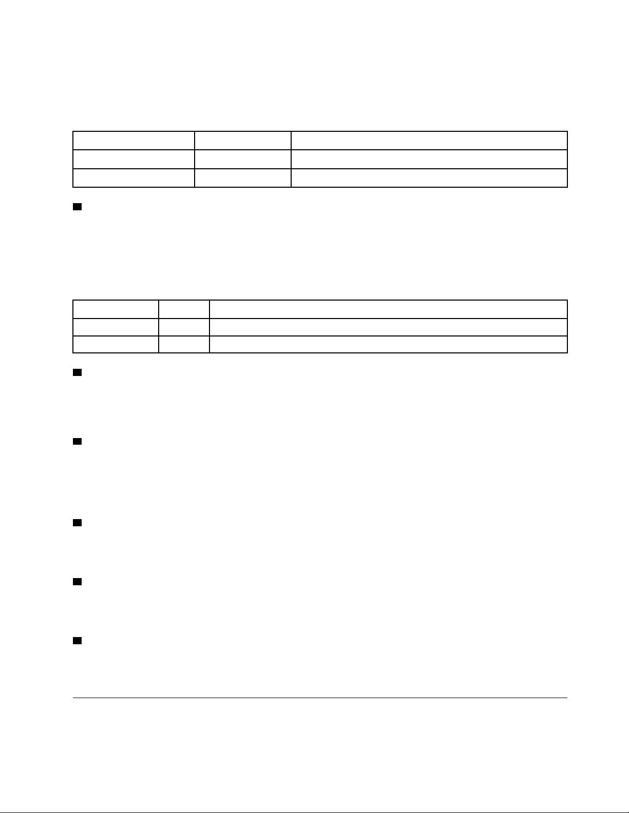
Figure 5. Side view
Table 7. Side view
1 Intrusion switch
9 M.2 drive*
2 Drive bay 3 (One 3.5-inch SATA drive)* 10 Drive bay 2 (One 2.5-inch SATA drive)*
3 ODD drive bay (One 9mm slim SATA Optical disk drive)
*
11 Drive bay 1 (One 3.5-inch SATA drive)
4 Front bezel 12 Power supply unit
5 3V CMOS battery (CR2032) 13 PCIe slot 1–3
6 SATA 1–4 connectors 14 PCIe adapter retainer
7 Front fan
15 Cage bar
8 Mono amplifier (speaker)
16 Rear fan
* Optional components.
Rear view
Refer this section to identify important components on the rear of the server.
14
ThinkSystem ST50 V2 Maintenance Manual
Figure 6. Rear view
Table 8. Rear view
1 Padlock loop
8 Two USB 3.2 Gen1 connectors
2 PCIe slot 1 9 1 GB RJ45 Ethernet connector
3 PCIe slot 2 10 DisplayPort 2 connector (Supported by processor
with integrated graphic feature only.)
4 PCIe slot 3 11 DisplayPort 1 connector (Supported by processor
with integrated graphic feature only.)
5 Kensington lock
12 Serial port connector
6 Power cord connector
13 Audio line-out connector (Windows Client OS only)
7 Two USB 3.2 Gen1 connectors
Notes:
• USB 3.2 Gen 1: 5 Gbps = 640 MB/s
• USB 3.2 Gen 2: 10 Gbps = 1280 MB/s
1 Padlock loop
This loop is available for installing a padlock. See “Server locks” on page 17 for more information.
Chapter 2. Server components 15
2 PCIe slot 1
PCIe slot 1 is a PCI Express 4.0 x16 expansion slot that is compatible with FHHL 75W PCIe adapter.
3 PCIe slot 2
PCIe slot 2 is a PCI Express 3.0 x1 slot that is compatible with FHHL 25W PCIe adapter.
4 PCIe slot 3
PCIe slot 3 is a PCI Express 3.0 x4 in x16 slot that is compatible with FHHL 25W PCIe adapter.
5 Kensington lock
This loop is available for installing a Kensington lock. See
“Server locks” on page 17 for more information.
6 Power cord connector
Connect the power cord to this component.
7 8 USB 3.2 Gen1 connectors
There are four USB 3.1 Gen1 connectors on the front panel. These connectors are available for a device that
require USB 3.0 connection, such as a keyboard, a mouse, or a USB flash drive.
9 1 GB RJ45 Ethernet connector
Connect an Ethernet cable to this connector for a LAN . This connector comes with LED for status indication.
Table 9. Ethernet connector LED behavior
Color Description
Yellow The network is connected and active.
Orange The network bandwidth is 1Gb
Green
The network bandwidth is 100MB
10 11 DisplayPort connectors
Connect a DisplayPort-compatible video device, such as a monitor, to this connector.
Supported by processor with integrated graphic feature only. See the “Processor” section at
“Specifications”
on page 2
for more information.
12 Serial port connector
Connect a 9-pin serial device to this connector.
13 Audio line-out connector
Connect a audio device, such as speakers or earphones, to this connector.
Notes:
1. This connector is only supported by Windows Client OS.
2. User may be aware of the low frequency noise via audio port in particular environments.
3. Excessive sound pressure from earphone/headphone can cause hearing damage.
16
ThinkSystem ST50 V2 Maintenance Manual
Server locks
Locking the server cover prevents unauthorized access to the inside of your server.
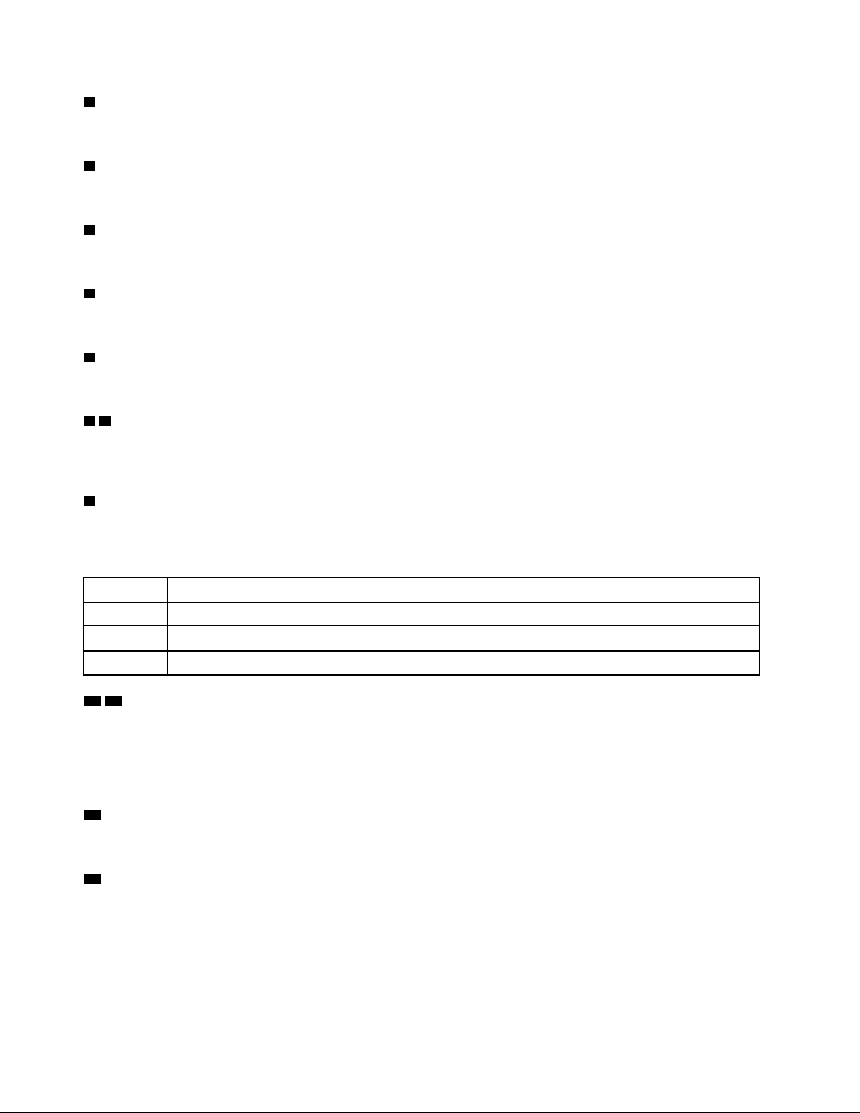
Kensington-style cable lock
You can use a Kensington-style cable lock to secure your server to a desk, table, or other non-permanent
fixture. The cable lock attaches to the security-lock slot at the rear of the server, and is operated with a key or
combination. The cable lock also locks the buttons used to remove the server cover. This is the same type of
lock used with many notebook computers. You can order an integrated cable lock directly from Lenovo by
searching for Kensington at:
http://datacentersupport.lenovo.com
Figure 7. Kensington-style cable lock
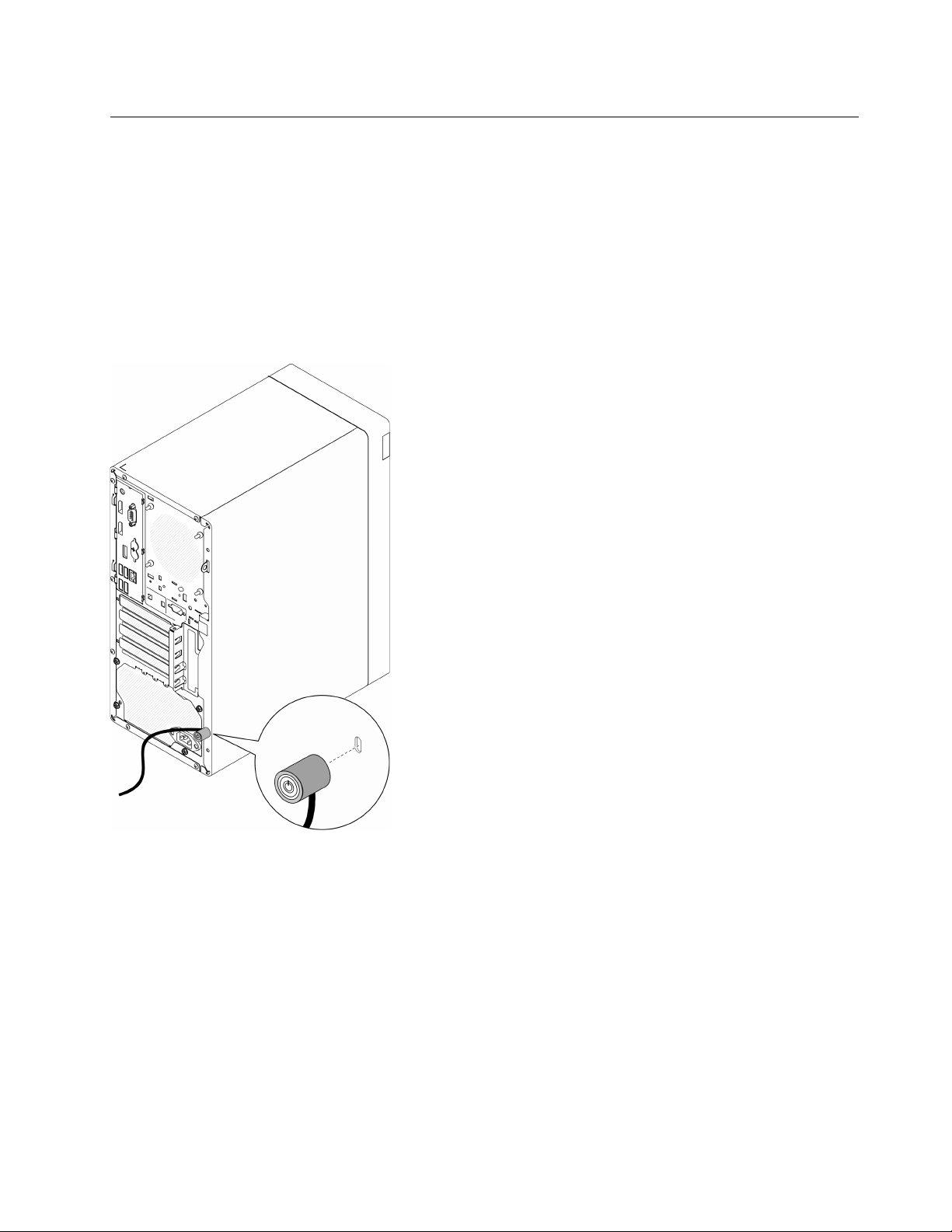
Padlock
This server comes with a padlock loop. When a padlock is installed, the server cover cannot be removed.
Chapter 2. Server components 17
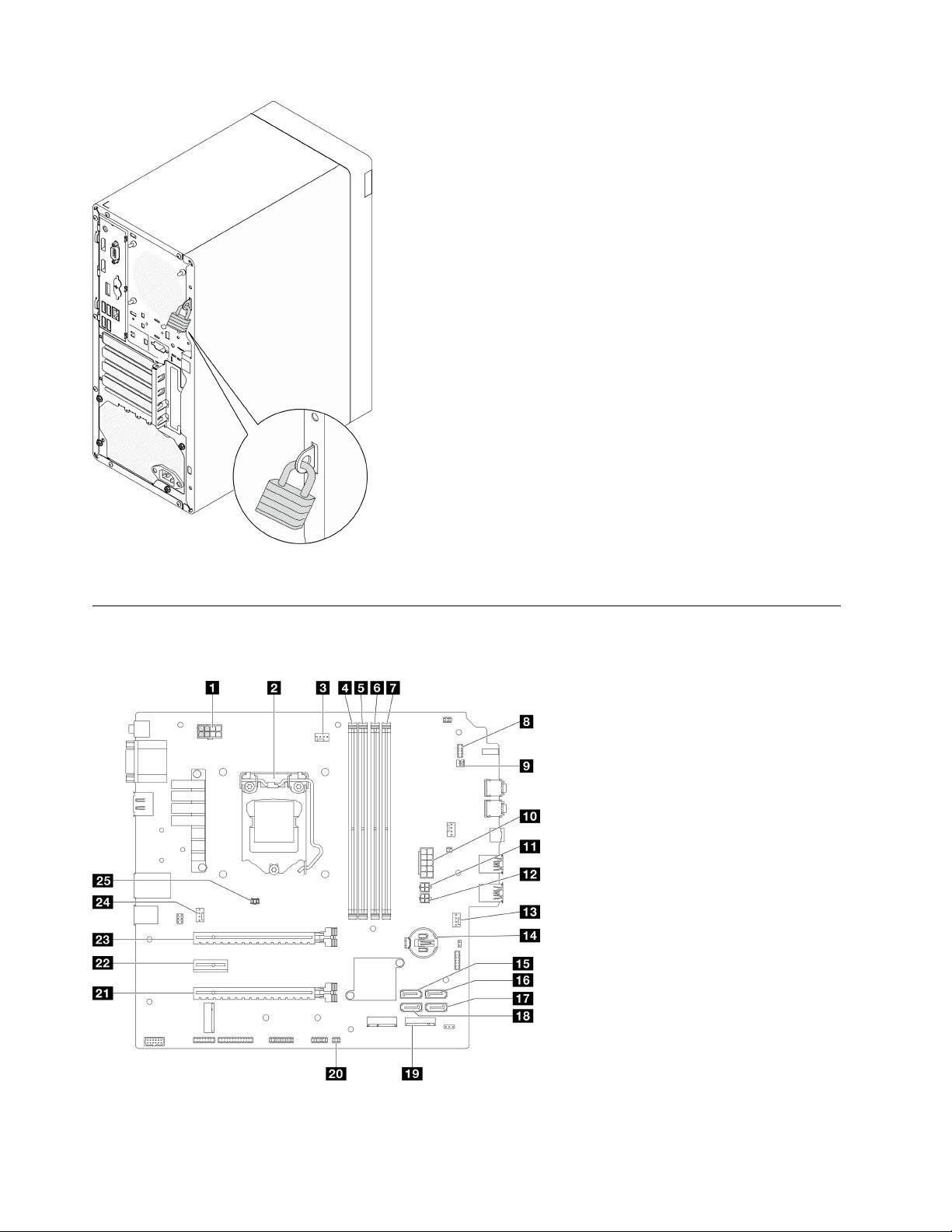
Figure 8. Padlock
System board components
The illustration in this section shows the component locations on the system board.
Figure 9. System board components
18 ThinkSystem ST50 V2 Maintenance Manual
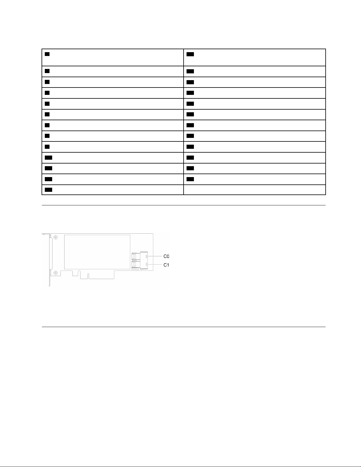
Table 10. Components on the system board
1 Processor power connector
Note: The 2x2 pins marked in grey are for 300W PSU.
14 3V battery (CR2032)
2 Processor
15 SATA 3 connector (drive bay 3)
3 Processor heat sink fan power connector
16 SATA 4 connector (ODD drive)
4 Memory module slot 1
17 SATA 2 connector (drive bay 2)
5 Memory module slot 2
18 SATA 1 connector (drive bay 1)
6 Memory module slot 3 19 M.2 connector
7 Memory module slot 4 20 Thermal sensor connector
8 Power button with LED connector
21 PCIe slot 3 (PCI Express 3.0 x4 )
9 Mono amplifier (speaker) connector 22 PCIe slot 2 (PCI Express 3.0 x1)
10 System power connector 23 PCIe slot 1 (PCI Express 4.0 x16)
11 SATA power 1 connector
24 Rear fan connector
12 SATA power 2 connector
25 Intrusion switch connector
13 Front fan connector
RAID adapters
Use this information to locate the connectors on the optional RAID adapters.
Figure 10. Connectors on SATA/SAS RAID adapter (8i)
Note: The RAID adapter should be installed in PCIe slot 1.
Internal cable routing
Some of the components in the server come with internal cables meant for specific connectors.
Cable routing guidelines
Before connecting the cables, read the following guidelines carefully:
• Turn off the server before you connect or disconnect any internal cables.
• Refer to the documentation that comes with any external devices for additional cabling instructions.
• Make use of the identifiers printed on the cables to locate the proper connectors.
• Ensure that the cable is not pinched and does not cover any connectors or obstruct any components on
the system board.
Chapter 2. Server components 19
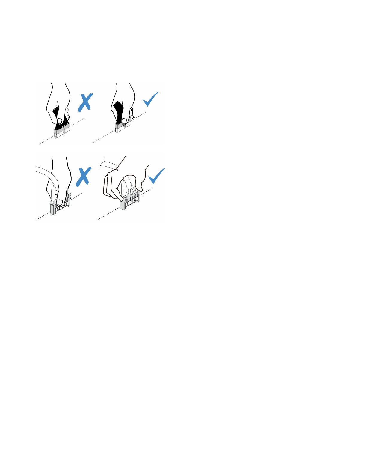
Note: Disengage all latches, release tabs, or locks on cable connectors when you disconnect cables from
the system board. Failing to release them before removing the cables will damage the cable sockets on the
system board, which are fragile. Any damage to the cable sockets might require replacing the system board.
Figure 11. Pressing the release tab to disengage the connector
Figure 12. Squeezing the release tabs at both sides to disengage the connector
20 ThinkSystem ST50 V2 Maintenance Manual
Cable routing for drive bay 1 and bay 2
Read this section to learn about cable routing for the drive in bay 1 and bay 2.
Drive bay 1
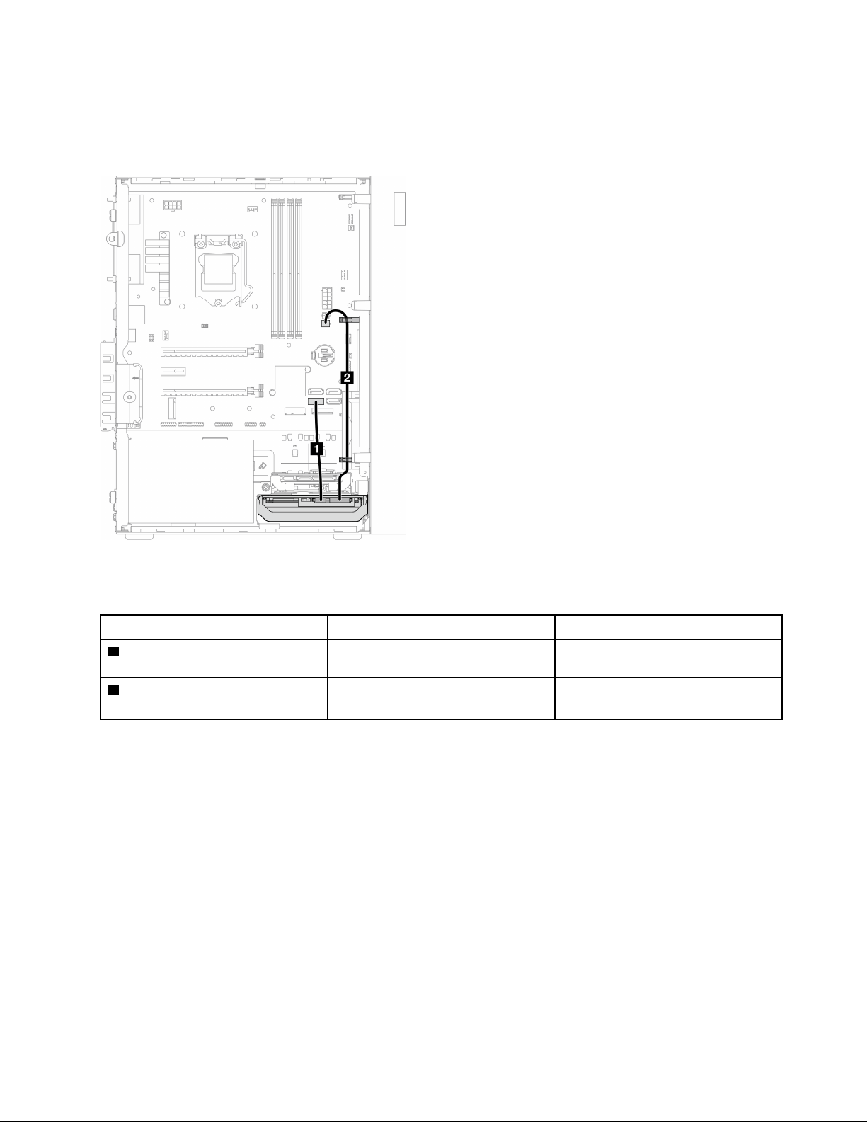
Figure 13. Cable routing for drive bay 1
Table 11. Cable routing for drive bay 1
Cable From To
1 1st 3.5 or 2.5 HDD SATA cable,
185 mm
Bay 1 drive signal connector
SATA 1 connector
2 1st 3.5 and 2.5 HDD Power Cable
(300 mm + 80 mm)
Bay 1 drive power connector SATA power 2 connector
Make sure to follow the “Cable routing guidelines” in
“Internal cable routing” on page 19.
For the system-board connector locations, see
“System board components” on page 18.
Chapter 2. Server components 21
Drive bay 2
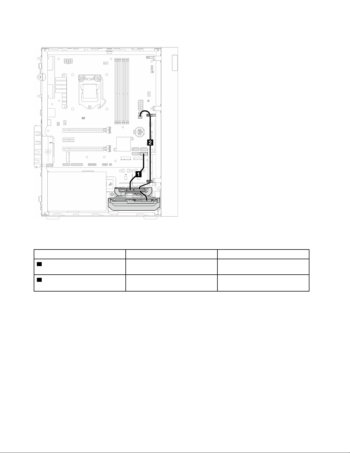
Figure 14. Cable routing for drive bay 2
Table 12. Cable routing for drive bay 2
Cable
From To
1 1st 3.5 or 2.5 HDD SATA cable,
185 mm
Bay 2 drive signal connector
SATA 2 connector
2 1st 3.5 and 2.5 HDD Power Cable
(300 mm + 80 mm)
Bay 2 drive power connector and bay
1 drive power connector
SATA power 2 connector
Make sure to follow the “Cable routing guidelines” in
“Internal cable routing” on page 19.
For the system-board connector locations, see
“System board components” on page 18.
22
ThinkSystem ST50 V2 Maintenance Manual
Cable routing for drive bay 3
Read this section to learn about cable routing for the drive in bay 3.
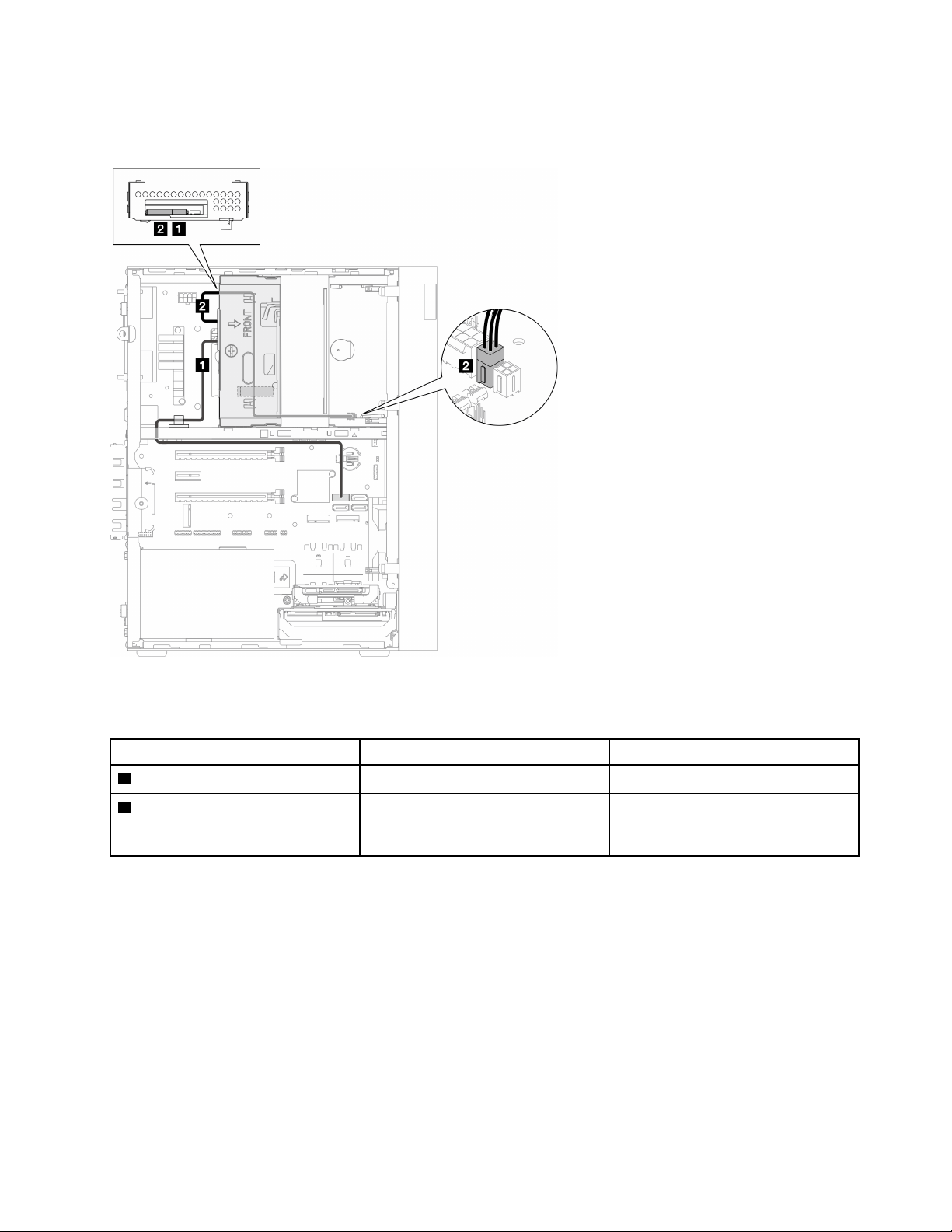
Figure 15. Cable routing for drive bay 3
Table 13. Cable routing for drive bay 3
Cable From To
1 SATA cable 1 latch (520 mm)
Bay 3 drive signal connector
SATA 3 connector
2 Slim ODD, second 3.5-inch drive
and 2.5-inch drive power cable ( 300
mm + 210 mm + 110 mm)
Bay 3 drive power connector SATA power 1 connector
Make sure to follow the “Cable routing guidelines” in
“Internal cable routing” on page 19.
For the system-board connector locations, see
“System board components” on page 18.
Chapter 2. Server components 23
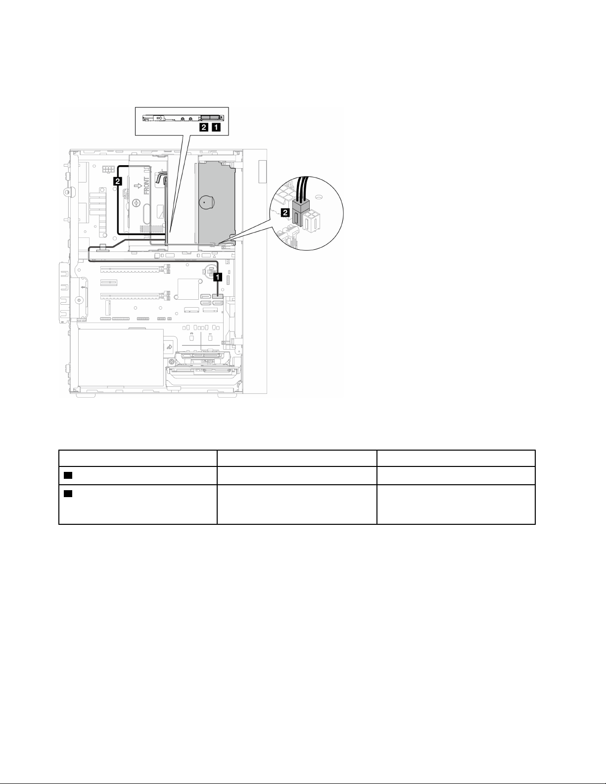
Cable routing for optical disk drive
Read this section to learn about cable routing for the optical disk drive.
Figure 16. Cable routing for optical disk drive
Table 14. Cable routing for optical disk drive
Cable From To
1 SATA cable 1 latch (520 mm) Optical disk drive signal connector
SATA 4 connector
2 Slim ODD, second 3.5-inch drive
and 2.5-inch drive power cable ( 300
mm + 210 mm + 110 mm)
Optical disk drive power connector SATA power 1 connector
Make sure to follow the “Cable routing guidelines” in
“Internal cable routing” on page 19.
For the system-board connector locations, see
“System board components” on page 18.
24
ThinkSystem ST50 V2 Maintenance Manual
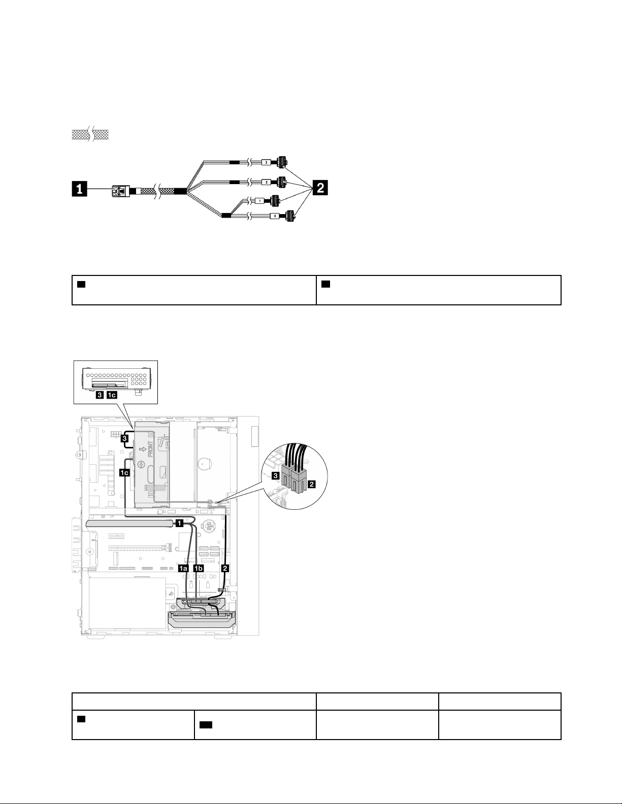
Cable routing for the RAID adapter and drives
Read this section to learn about cable routing for the RAID adapter and drives.
RAID adapter cable
The break lines indicate that part of the cable is hidden in the illustration.
Figure 17. Mini SAS HD to 4 SATA 7-pin cable
Table 15. Mini SAS HD to 4 SATA 7-pin cable
1 Connector for the RAID adapter (connector C0). See
“RAID adapters” on page 19.
2 Connectors for the drives
Cable routing for three drives with the RAID adapter
Note: The RAID adapter should be installed in PCIe slot 1.
Figure 18. Cable routing for three drives with the RAID adapter
Table 16. Cable routing for three drives with the RAID adapter
Cable
From To
1 Mini SAS HD to 4 SATA
7-pin cable
1a cable labeled as “0”
Bay 1 drive signal
connector
C0 connector on the RAID
adapter
Chapter 2. Server components 25
Table 16. Cable routing for three drives with the RAID adapter (continued)
Cable
From To
1b cable labeled as “1”
Bay 2 drive signal
connector
1c cable labeled as “2”
Bay 3 drive signal
connector
2 1st 3.5 and 2.5 HDD Power Cable (300 mm + 80 mm)
Bay 2 drive power
connector and bay 1 drive
power connector
SATA power 2 connector
3 Slim ODD, second 3.5-inch drive and 2.5-inch drive
power cable ( 300 mm + 210 mm + 110 mm)
Bay 3 drive power
connector
SATA power 1 connector
Make sure to follow the “Cable routing guidelines” in
“Internal cable routing” on page 19.
For the system-board connector locations, see
“System board components” on page 18.
26
ThinkSystem ST50 V2 Maintenance Manual
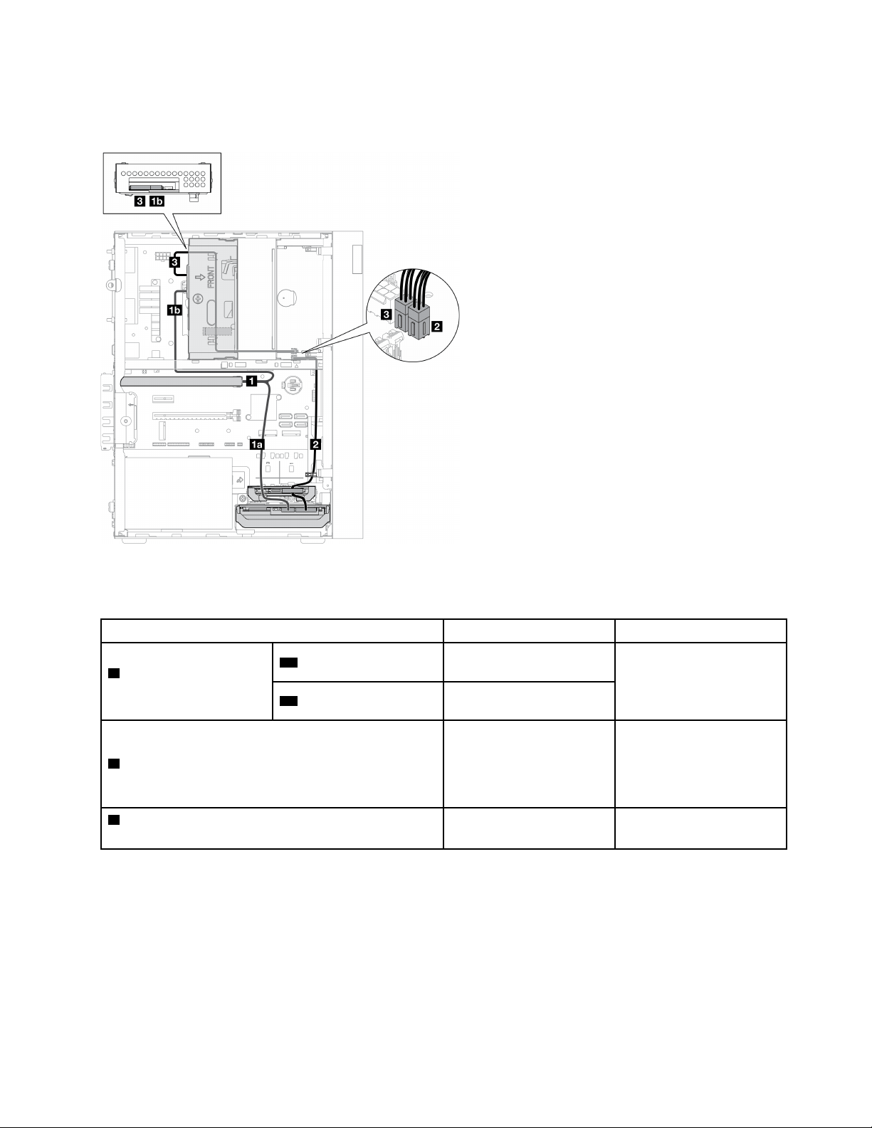
Cable routing for two drives with the RAID adapter
Note: The RAID adapter should be installed in PCIe slot 1.
Figure 19. Cable routing for two drives with the RAID adapter
Table 17. Cable routing for two drives with the RAID adapter
Cable
From To
1 Mini SAS HD to 4 SATA
7-pin cable
1a cable labeled as “0”
Bay 1 drive signal
connector
C0 connector on the RAID
adapter
1b cable labeled as “2”
Bay 3 drive signal
connector
2 1st 3.5 and 2.5 HDD Power Cable (300 mm + 80 mm)
Bay 2 drive power
connector* and bay 1 drive
power connector
Note: * Depending on
server configuration.
SATA power 2 connector
3 Slim ODD, second 3.5-inch drive and 2.5-inch drive
power cable ( 300 mm + 210 mm + 110 mm)
Bay 3 drive power
connector
SATA power 1 connector
Make sure to follow the “Cable routing guidelines” in
“Internal cable routing” on page 19.
For the system-board connector locations, see
“System board components” on page 18.
Chapter 2. Server components 27
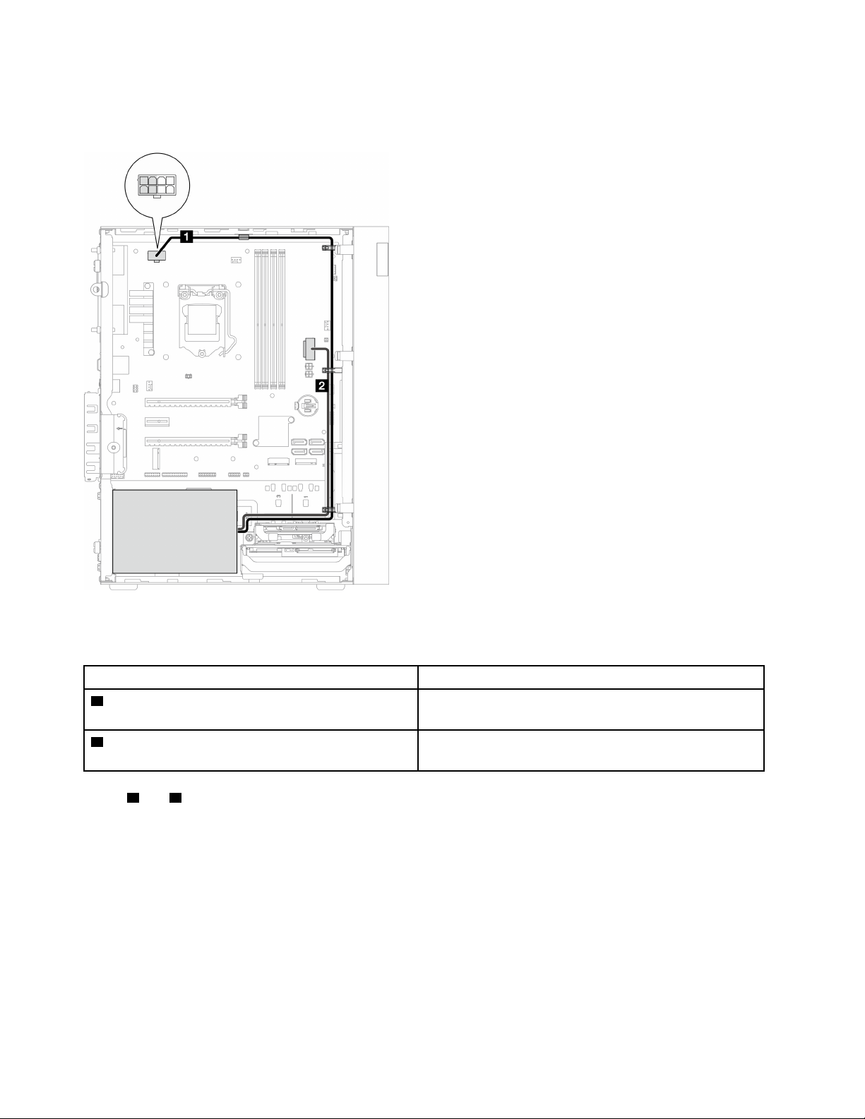
Cable routing for the power supply unit
Read this section to learn about cable routing for the power supply unit.
Figure 20. Cable routing for the power supply unit
Table 18. Cable routing for the power supply unit
From To
1 Micro-fit to 1X15P and 1X4P Y-splitter power cable
(4-pin or 8-pin SATA connector for processor power)
Processor power connector
Note: The 2x2 pins marked in grey are for 300W PSU.
2 Micro-fit to 1X15P and 1X4P Y-splitter power cable
(15-pin connector for system power)
System power connector
Note:
1 and 2 are parts of the same Y-splitter cable.
Make sure to follow the “Cable routing guidelines” in
“Internal cable routing” on page 19.
For the system-board connector locations, see
“System board components” on page 18.
28
ThinkSystem ST50 V2 Maintenance Manual
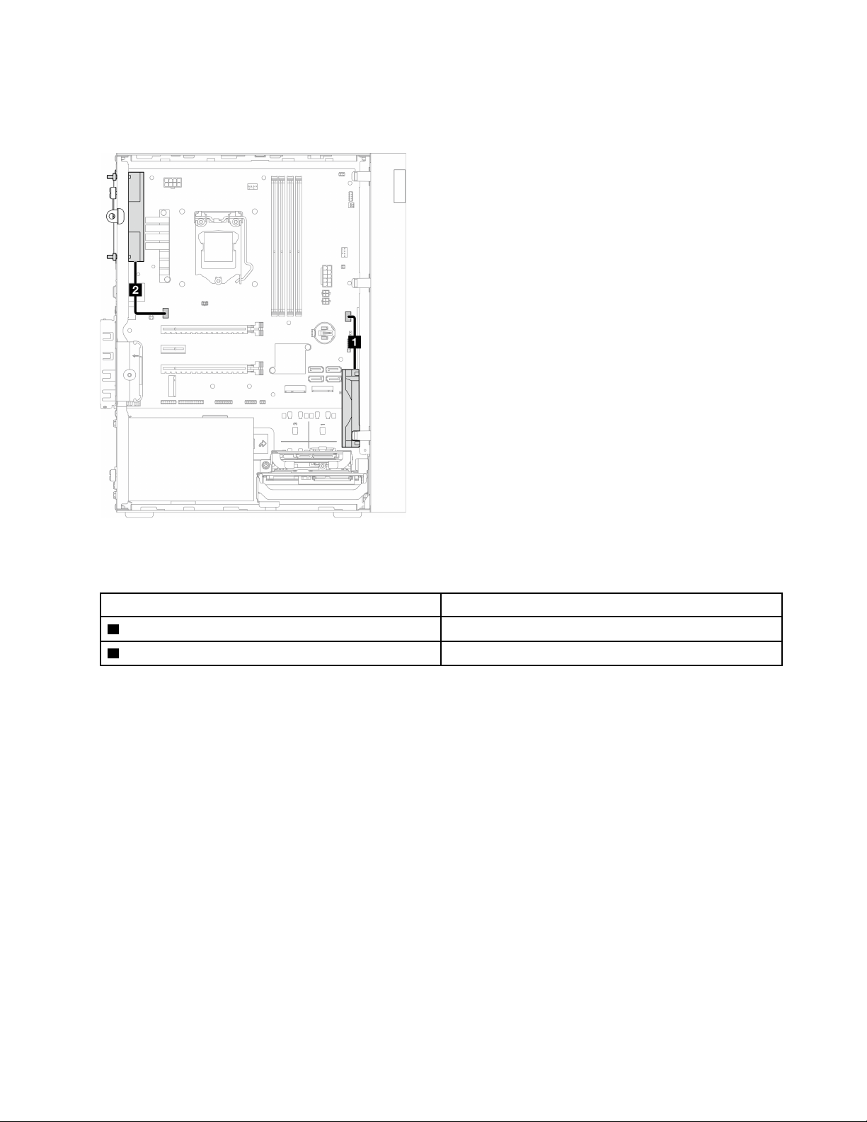
Cable routing for the front fan and rear fan
Read this section to learn about cable routing for the front fan and rear fan.
Figure 21. Cable routing for the front fan and rear fan
Table 19. Cable routing for the heat sink and fan module
From To
1 Front fan cable
Front fan connector
2 Rear fan cable
Rear fan connector
Make sure to follow the “Cable routing guidelines” in
“Internal cable routing” on page 19.
For the system-board connector locations, see
“System board components” on page 18.
Chapter 2. Server components 29
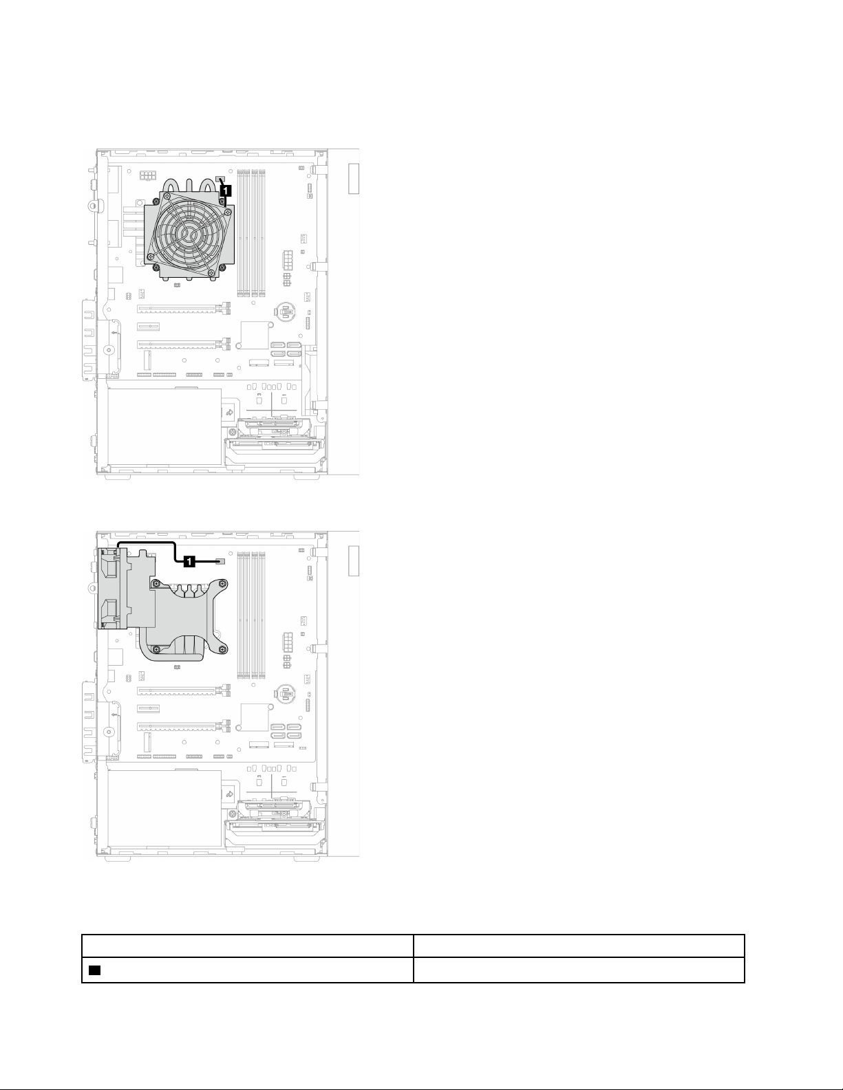
Cable routing for the heat sink and fan module
Read this section to learn about cable routing for the heat sink and fan module.
Figure 22. Cable routing for the heat sink and fan module for processor with TDP lower than 95W
Figure 23. Cable routing for the heat sink and fan module for processor with 95W TDP
Table 20. Cable routing for the heat sink and fan module
From To
1 Heat sink and fan module cable
Processor heat sink fan power connector
30 ThinkSystem ST50 V2 Maintenance Manual


Cable routing for the intrusion switch
Read this section to learn about cable routing for the intrusion switch.
Figure 24. Cable routing for the intrusion switch
Table 21. Cable routing for the intrusion switch
From To
1 Intrusion switch cable
Intrusion switch connector
For the system-board connector locations, see
“System board components” on page 18.
32
ThinkSystem ST50 V2 Maintenance Manual
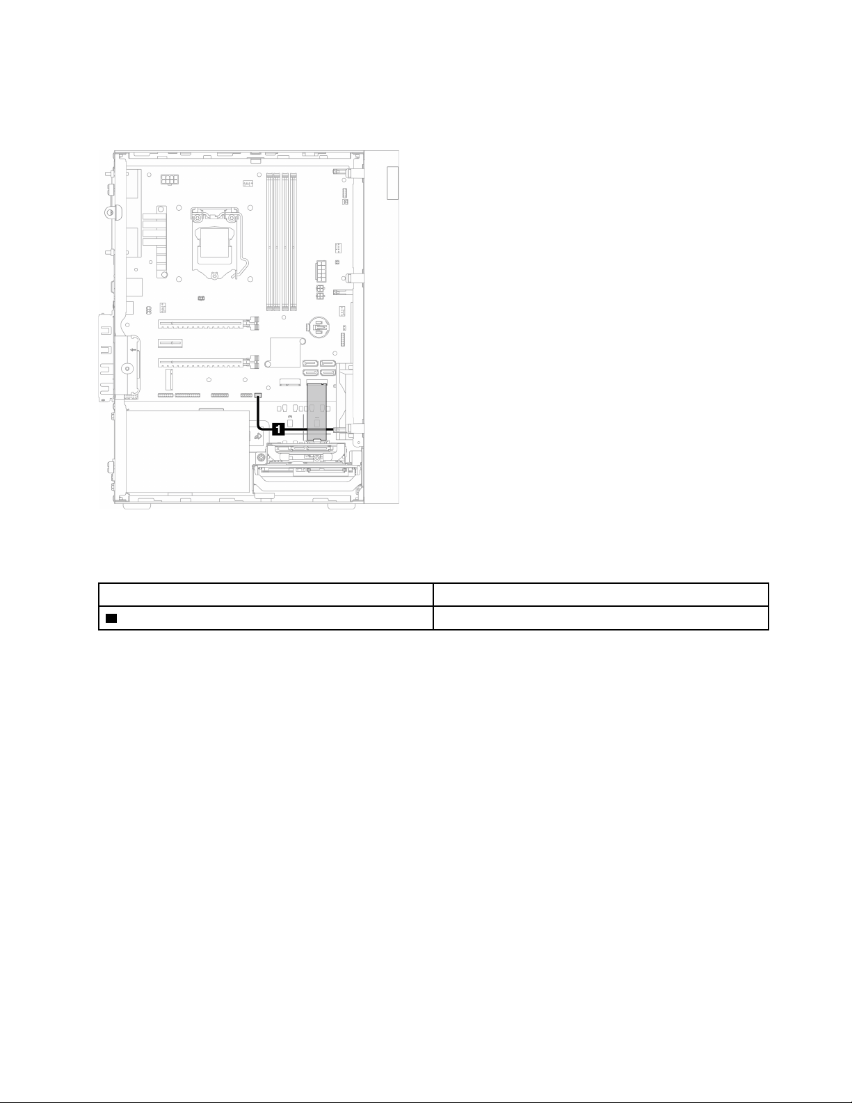
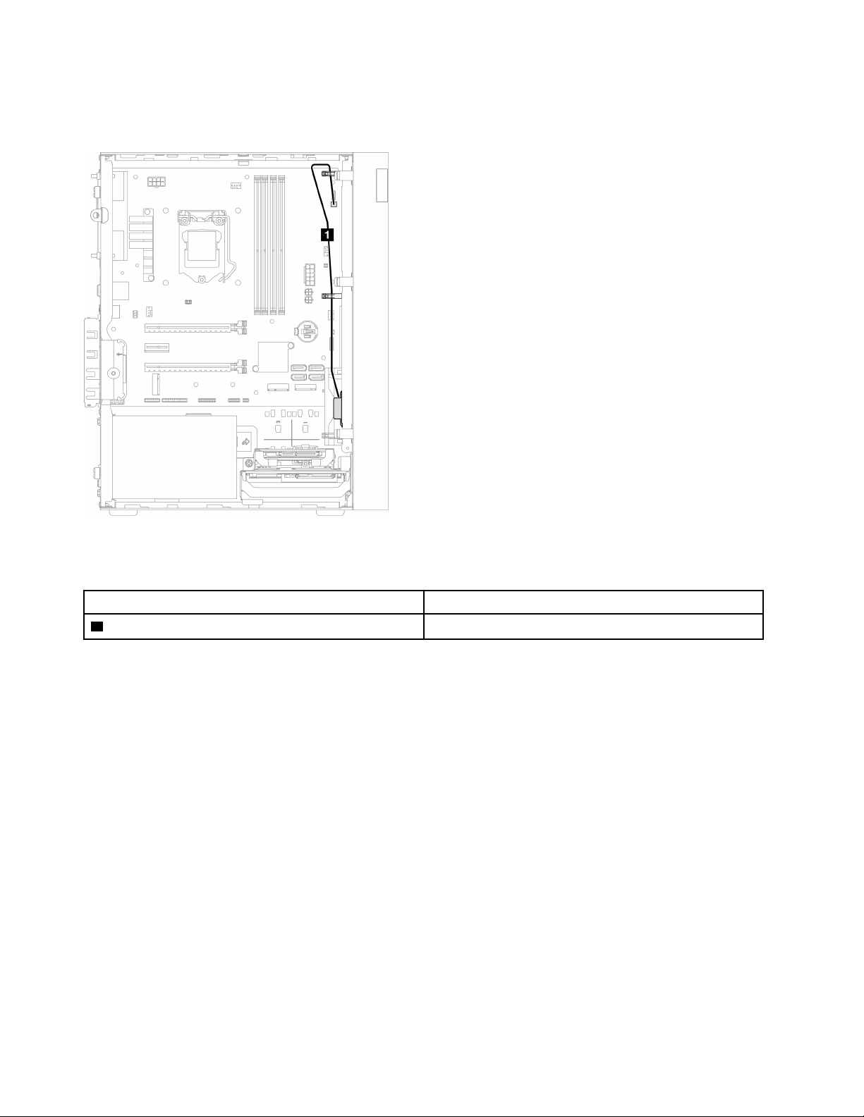
Cable routing for the thermal sensor
Read this section to learn about cable routing for the thermal sensor.
Figure 25. Cable routing for the thermal sensor
Table 22. Cable routing for the thermal sensor
From To
1 Thermal sensor cable
Thermal sensor connector
Note: If applicable, place the thermal sensor cable under the M.2 drive.
Make sure to follow the “Cable routing guidelines” in
“Internal cable routing” on page 19.
For the system-board connector locations, see
“System board components” on page 18.
Chapter 2. Server components 33
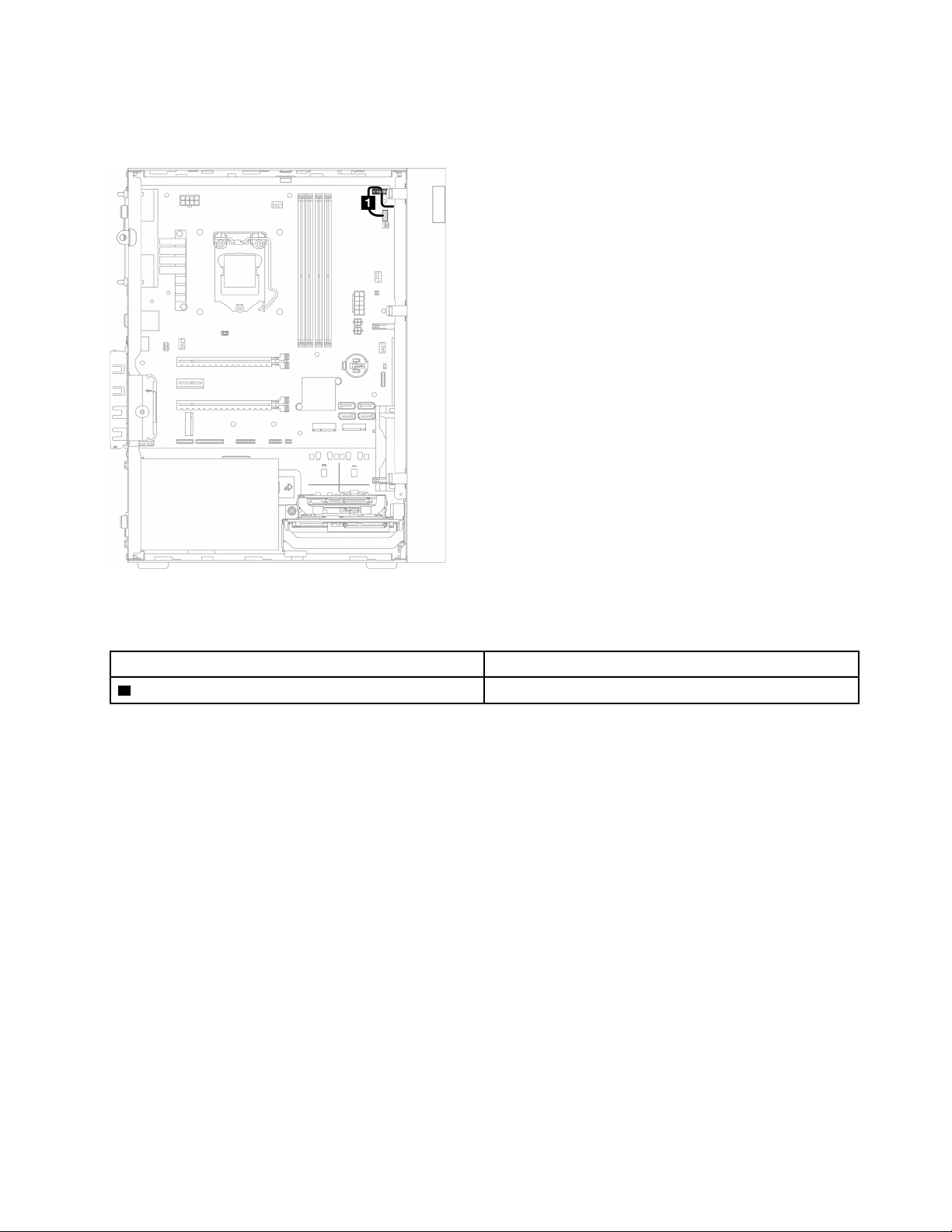
Cable routing for the mono amplifier
Read this section to learn about cable routing for the mono amplifier.
Figure 26. Cable routing for the mono amplifier
Table 23. Cable routing for the mono amplifier
From To
1 Mono amplifier cable Mono amplifier connector
Make sure to follow the “Cable routing guidelines” in
“Internal cable routing” on page 19.
For the system-board connector locations, see
“System board components” on page 18.
34
ThinkSystem ST50 V2 Maintenance Manual
Cable routing for the power button with LED
Read this section to learn about cable routing for the power button with LED.
Figure 27. Cable routing for the power button with LED
Table 24. Cable routing for the power button with LED
From To
1 Power button with LED cable
Power button with LED connector
Make sure to follow the “Cable routing guidelines” in
“Internal cable routing” on page 19.
For the system-board connector locations, see
“System board components” on page 18.
Chapter 2. Server components 35
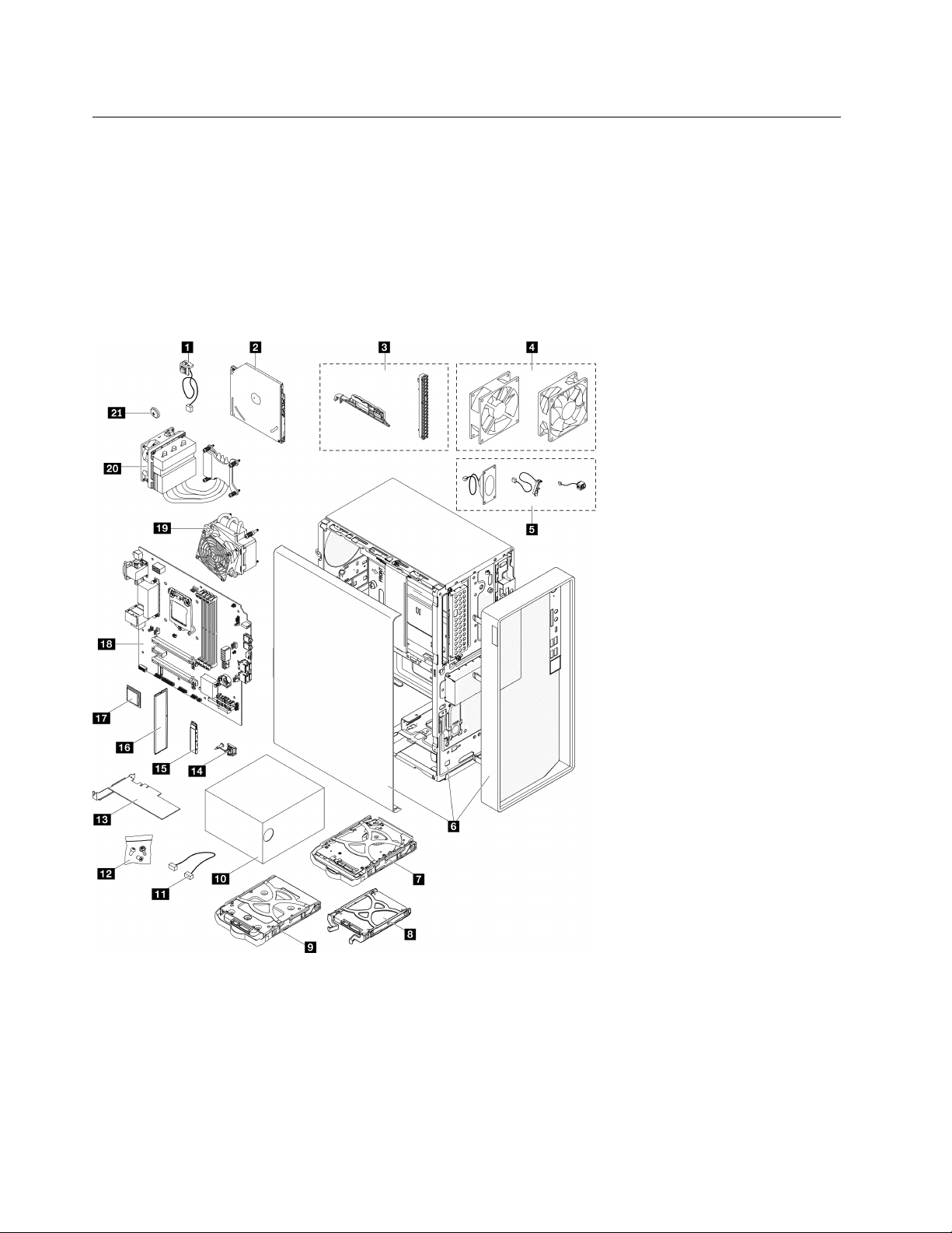
Parts list
Use the parts list to identify each of the components that are available for your server.
Note: Depending on the model, your server might look slightly different from the illustration.
For more information about ordering parts:
1. Go to
http://datacentersupport.lenovo.com and navigate to the support page for your server.
2. Click Parts.
3. Enter the serial number to view a listing of parts for your server.
Figure 28. Server components
The parts listed in the following table are identified as one of the following:
• Tier 1 customer replaceable unit (CRU): Replacement of Tier 1 CRUs is your responsibility. If Lenovo
installs a Tier 1 CRU at your request with no service agreement, you will be charged for the installation.
• Tier 2 customer replaceable unit (CRU): You may install a Tier 2 CRU yourself or request Lenovo to
install it, at no additional charge, under the type of warranty service that is designated for your server.
36 ThinkSystem ST50 V2 Maintenance Manual

• Field replaceable unit (FRU): FRUs must be installed only by trained service technicians.
• Consumable and Structural parts: Purchase and replacement of consumable and structural parts is
your responsibility. If Lenovo acquires or installs a structural component at your request, you will be
charged for the service.
Table 25. Parts listing
Index
Description
Tier 1 CRU Tier 2 CRU FRU
Consumable
and Structural
parts
For more information about ordering parts:
1. Go to
http://datacentersupport.lenovo.com and navigate to the support page for your server.
2. Click Parts.
3. Enter the serial number to view a listing of parts for your server.
1
Intrusion switch
√
2
Optical disk drive
√
3
Bezel kit (including the optical disk
drive bezel and latch)
√
4
Fan kit (including the front fan and rear
fan)
√
5
Cable kit (including the mono amplifier,
thermal sensor, and the power button
cable)
√
6
Chassis (with front bezel and server
cover)
√
7
3.5-inch hard-disk drive assembly
√
8
2.5-inch solid-state drive assembly
√
9
3.5-inch solid-state drive assembly
√
10
Power supply unit
√
11
Cable
√
12
Screw kit
√
13
PCIe adapter
√
14
M.2 drive retainer
√
15
M.2 drive
√
16
Memory module
√
17
Processor
√
18
System board
√
19
Heat sink and fan module (for
processor with TDP lower than 95W)
√
Chapter 2. Server components 37
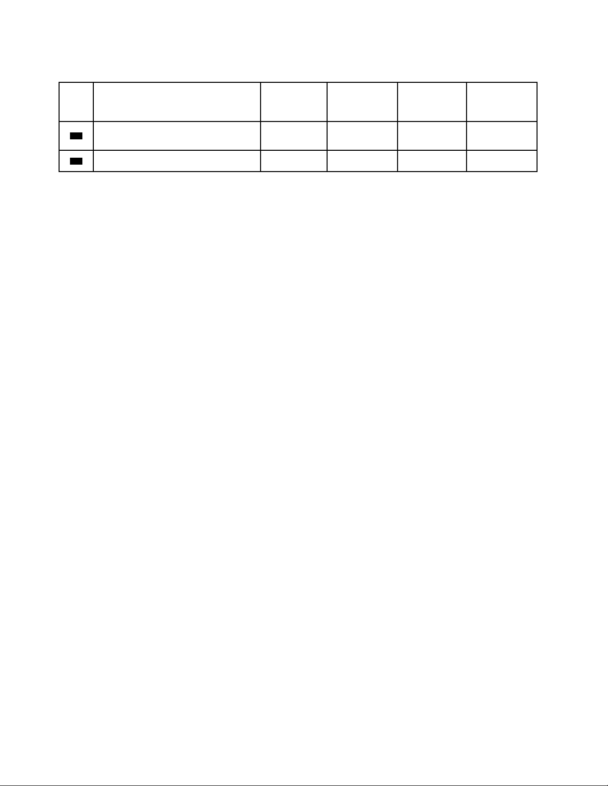
Table 25. Parts listing (continued)
Index
Description
Tier 1 CRU Tier 2 CRU FRU
Consumable
and Structural
parts
20
Heat sink and fan module (for
processor with 95W TDP)
√
21
3V CMOS battery (CR2032)
√
38 ThinkSystem ST50 V2 Maintenance Manual

Power cords
Several power cords are available, depending on the country and region where the server is installed.
To view the power cords that are available for the server:
1. Go to:
http://dcsc.lenovo.com/#/
2. Click Preconfigured Model or Configure to order.
3. Enter the machine type and model for your server to display the configurator page.
4. Click Power ➙ Power Cables to see all line cords.
Notes:
• For your safety, a power cord with a grounded attachment plug is provided to use with this product. To
avoid electrical shock, always use the power cord and plug with a properly grounded outlet.
• Power cords for this product that are used in the United States and Canada are listed by Underwriter's
Laboratories (UL) and certified by the Canadian Standards Association (CSA).
• For units intended to be operated at 115 volts: Use a UL-listed and CSA-certified cord set consisting of a
minimum 18 AWG, Type SVT or SJT, three-conductor cord, a maximum of 15 feet in length and a parallel
blade, grounding-type attachment plug rated 15 amperes, 125 volts.
• For units intended to be operated at 230 volts (U.S. use): Use a UL-listed and CSA-certified cord set
consisting of a minimum 18 AWG, Type SVT or SJT, three-conductor cord, a maximum of 15 feet in length
and a tandem blade, grounding-type attachment plug rated 15 amperes, 250 volts.
• For units intended to be operated at 230 volts (outside the U.S.): Use a cord set with a grounding-type
attachment plug. The cord set should have the appropriate safety approvals for the country in which the
equipment will be installed.
• Power cords for a specific country or region are usually available only in that country or region.
Chapter 2. Server components 39

40 ThinkSystem ST50 V2 Maintenance Manual

Chapter 3. Hardware replacement procedures
This section provides installation and removal procedures for all serviceable system components. Each
component replacement procedure references any tasks that need to be performed to gain access to the
component being replaced.
For more information about ordering parts:
1. Go to
http://datacentersupport.lenovo.com and navigate to the support page for your server.
2. Click Parts.
3. Enter the serial number to view a listing of parts for your server.
Note: If you replace a part, such as an adapter, that contains firmware, you might also need to update the
firmware for that part.
Installation guidelines
Before installing components in your server, read the installation guidelines.
Before installing optional devices, read the following notices carefully:
Attention: Prevent exposure to static electricity, which might lead to system halt and loss of data, by
keeping static-sensitive components in their static-protective packages until installation, and handling these
devices with an electrostatic-discharge wrist strap or other grounding system.
• Read the safety information and guidelines to ensure that you work safely.
– A complete list of safety information for all products is available at:
http://thinksystem.lenovofiles.com/
help/topic/safety_documentation/pdf_files.html
– “Handling static-sensitive devices” on page 43
• Make sure the components you are installing are supported by the server. For a list of supported optional
components for the server, see
https://static.lenovo.com/us/en/serverproven/index.shtml.
• When you install a new server, download and apply the latest firmware. This will help ensure that any
known issues are addressed, and that your server is ready to work with optimal performance. Go to
https://datacentersupport.lenovo.com/tw/en/products/servers/thinksystem/st50v2/downloads/driver-list/ to
download firmware updates for your server.
Important: Some cluster solutions require specific code levels or coordinated code updates. If the
component is part of a cluster solution, verify that the latest level of code is supported for the cluster
solution before you update the code.
• It is good practice to make sure that the server is working correctly before you install an optional
component.
• Keep the working area clean, and place removed components on a flat and smooth surface that does not
shake or tilt.
• Do not attempt to lift an object that might be too heavy for you. If you have to lift a heavy object, read the
following precautions carefully:
– Make sure that you can stand steadily without slipping.
– Distribute the weight of the object equally between your feet.
– Use a slow lifting force. Never move suddenly or twist when you lift a heavy object.
– To avoid straining the muscles in your back, lift by standing or by pushing up with your leg muscles.
© Copyright Lenovo 2022, 2022 41

• Make sure that you have an adequate number of properly grounded electrical outlets for the server,
monitor, and other devices.
• Back up all important data before you make changes related to the disk drives.
• Have a small flat-blade screwdriver, a small Phillips screwdriver, and a T8 torx screwdriver available.
• You do not have to turn off the server to remove or install hot-swap power supplies or hot-plug USB
devices. However, you must turn off the server before you perform any steps that involve removing or
installing adapter cables, and you must disconnect the power source from the server before you perform
any steps that involve removing or installing a DIMM.
• Blue on a component indicates touch points, where you can grip to remove a component from or install it
in the server, open or close a latch, and so on.
• Terra cotta on a component or an orange label on or near a component indicates that the component can
be hot-swapped if the server and operating system support hot-swap capability, which means that you
can remove or install the component while the server is still running. (Orange can also indicate touch
points on hot-swap components.) See the instructions for removing or installing a specific hot-swap
component for any additional procedures that you might have to perform before you remove or install the
component.
• The Red strip on the drives, adjacent to the release latch, indicates that the drive can be hot-swapped if
the server and operating system support hot-swap capability. This means that you can remove or install
the drive while the server is still running.
Note: See the system specific instructions for removing or installing a hot-swap drive for any additional
procedures that you might need to perform before you remove or install the drive.
• After finishing working on the server, make sure you reinstall all safety shields, guards, labels, and ground
wires.
System reliability guidelines
Review the system reliability guidelines to ensure proper system cooling and reliability.
Make sure the following requirements are met:
• When the server comes with redundant power, a power supply must be installed in each power-supply
bay.
• Adequate space around the server must be spared to allow server cooling system to work properly. Leave
approximately 50 mm (2.0 in.) of open space around the front and rear of the server. Do not place any
object in front of the fans.
• For proper cooling and airflow, refit the server cover before you turn the power on. Do not operate the
server for more than 30 minutes with the server cover removed, for it might damage server components.
• Cabling instructions that come with optional components must be followed.
• A failed fan must be replaced within 48 hours since malfunction.
• A removed hot-swap drive must be replaced within two minutes after removal.
• A removed hot-swap power supply must be replaced within two minutes after removal.
• Every air baffle that comes with the server must be installed when the server starts (some servers might
come with more than one air baffle). Operating the server with a missing air baffle might damage the
processor.
• All processor sockets must contain either a socket cover or a processor with heat sink.
• When more than one processor is installed, fan population rules for each server must be strictly followed.
42
ThinkSystem ST50 V2 Maintenance Manual

Handling static-sensitive devices
Review these guidelines before you handle static-sensitive devices to reduce the possibility of damage from
electrostatic discharge.
Attention: Prevent exposure to static electricity, which might lead to system halt and loss of data, by
keeping static-sensitive components in their static-protective packages until installation, and handling these
devices with an electrostatic-discharge wrist strap or other grounding system.
• Limit your movement to prevent building up static electricity around you.
• Take additional care when handling devices during cold weather, for heating would reduce indoor
humidity and increase static electricity.
• Always use an electrostatic-discharge wrist strap or other grounding system.
• While the device is still in its static-protective package, touch it to an unpainted metal surface on the
outside of the server for at least two seconds. This drains static electricity from the package and from your
body.
• Remove the device from the package and install it directly into the server without putting it down. If it is
necessary to put the device down, put it back into the static-protective package. Never place the device
on the server or on any metal surface.
• When handling a device, carefully hold it by the edges or the frame.
• Do not touch solder joints, pins, or exposed circuitry.
• Keep the device from others’ reach to prevent possible damages.
Chapter 3. Hardware replacement procedures 43
Memory module installation rules
Memory modules must be installed in a specific order based on the memory configuration of the server.
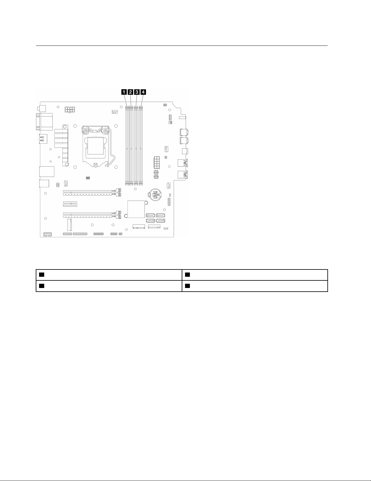
The following illustration shows the location of the memory module slots on the system board.
Figure 29. Memory module slots on the system board
Table 26. Memory module slots on the system board
1 Memory module slot 1 3 Memory module slot 3
2 Memory module slot 2 4 Memory module slot 4
Independent mode
This server supports independent mode only.
Independent mode provides high performance memory capability. You can populate all channels with no
matching requirements. Individual channels can run at different DIMM timings, but all channels must run at
the same interface frequency.
Make sure to adhere to the following rules:
• All memory modules installed should be identical in type and capacity.
• Do not mix memory modules with different voltages.
• Do not mix low-voltage and regular UDIMMs. (2R memory module only)
For a list of supported Memory module slot options, see:
https://static.lenovo.com/us/en/serverproven/
index.shtml
44 ThinkSystem ST50 V2 Maintenance Manual
Table 27. Memory module installation rules and order for Independent Mode
Total
memory
modules
Memory channel A Memory channel B
Slot 1 Slot 2
Slot 3 Slot 4
1 V
2*
V V
4†
V V V V
* See the following for the maximum memory speed supported:
• Maximum memory speed supported by same memory capacity:
– Xeon
®
E3–23XX: up to 3200 MT/s
– Pentium Gold: up to 2666 MT/s
† See the following for the maximum memory speed supported:
• 8GB 1Rx8 DIMM
– Xeon
®
E3–23XX: up to 3200 MT/s
– Pentium Gold: up to 2666 MT/s
• 16GB 2Rx8
– Xeon
®
E3–23XX: up to 2933 MT/s
– Pentium Gold: up to 2400 MT/s
CMOS battery (CR2032) replacement
Follow this procedure to remove and install the CMOS battery (CR2032).
Remove the CMOS battery (CR2032)
S002
CAUTION:
The power-control button on the device and the power switch on the power supply do not turn off the
electrical current supplied to the device. The device also might have more than one power cord. To
remove all electrical current from the device, ensure that all power cords are disconnected from the
power source.
Chapter 3. Hardware replacement procedures 45
S004
CAUTION:
When replacing the lithium battery, use only Lenovo specified part number or an equivalent type
battery recommended by the manufacturer. If your system has a module containing a lithium battery,
replace it only with the same module type made by the same manufacturer. The battery contains
lithium and can explode if not properly used, handled, or disposed of.
Do not:
• Throw or immerse into water
• Heat to more than 100°C (212°F)
• Repair or disassemble
Dispose of the battery as required by local ordinances or regulations.
S005
CAUTION:
The battery is a lithium ion battery. To avoid possible explosion, do not burn the battery. Exchange it
only with the approved part. Recycle or discard the battery as instructed by local regulations.
About this task
Attention:
• Read
“Safety inspection checklist” on page iv and “Installation guidelines” on page 41 to ensure that you
work safely.
• Turn off the server and peripheral devices, and disconnect the power cords and all external cables, see
“Power off the server” on page 9.
• If the server is in a rack, remove it from the rack. See
“Remove the server from the rails” on page 138.
• Remove any locking device that secures the server, such as a Kensington lock or a padlock.
• Place the server on its side with the cover up.
Watch the procedure
A video of this procedure is available at YouTube:
https://www.youtube.com/playlist?list=PLYV5R7hVcs-
AU3iY3F7lq3qfqr5caGbIu
.
Procedure
Step 1. Make preparation for the task.
a. Remove the server cover, see “Remove the server cover” on page 144.
46
ThinkSystem ST50 V2 Maintenance Manual
Note: The heat sink and processor could be very hot. To avoid burning yourself, wait for a few
minutes after turning off the server before you remove the server cover.
Step 2. Locate the CMOS battery on the system board. See
“System board components” on page 18.
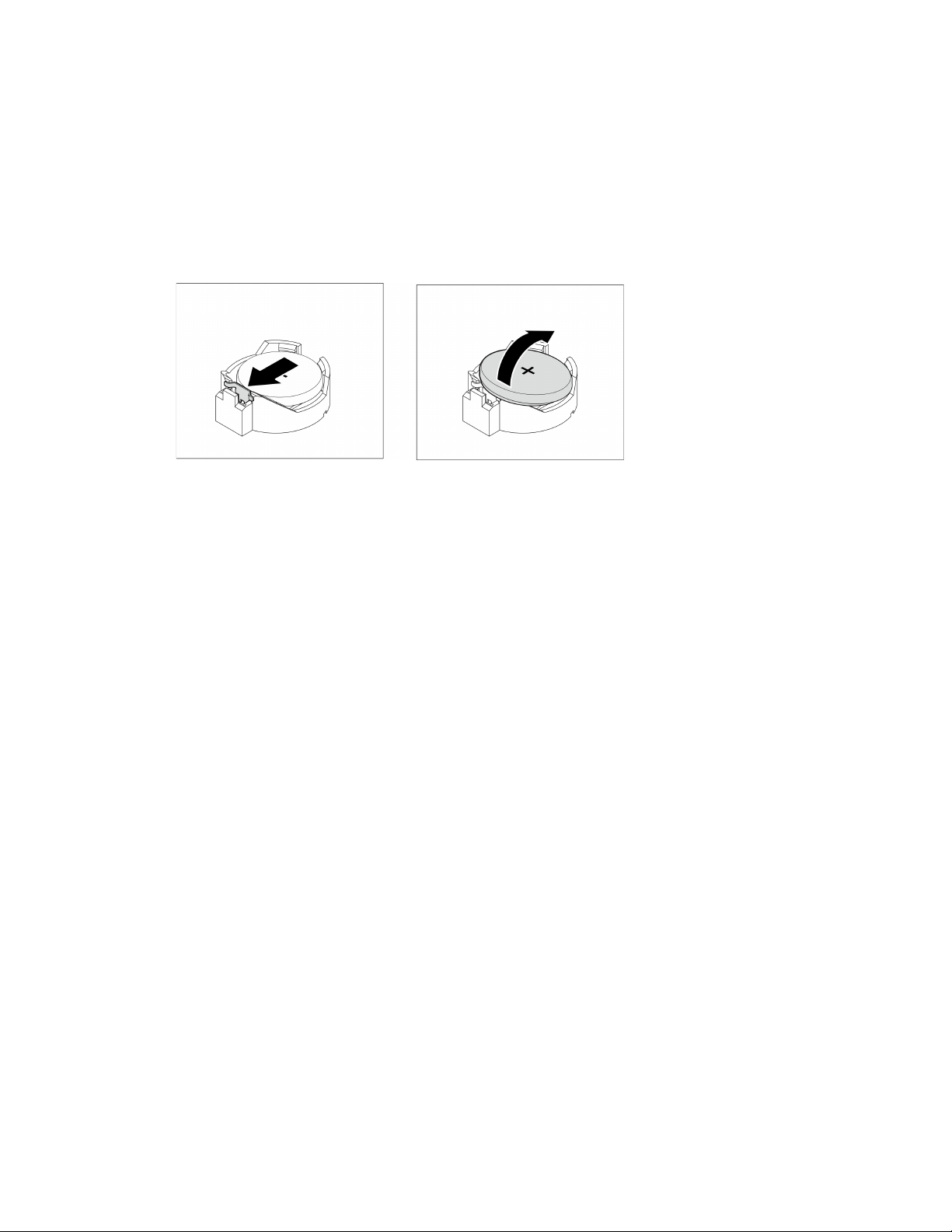
Step 3. Gently press on the nub on the side of the CMOS battery as illustrated; then, pivot the battery away
from the seat to remove it.
Attention: Avoid excessive force on the CMOS battery, as it might damage the socket on the
system board and result in system board replacement.
Figure 30. Removing the CMOS battery (CR2032)
After you finish
1. Install a new CMOS battery. See
“Install the CMOS battery (CR2032)” on page 47.
Note: Make sure to install the CMOS battery before powering on the server. Otherwise, it might cause
system abnormality.
2. Dispose the CMOS battery as required by local ordinances or regulations.
Install the CMOS battery (CR2032)
Consider the following when replacing the CMOS battery in the server:
• When replacing the CMOS battery, you must replace it with another CMOS battery of the same type from
the same manufacturer.
• After replacing the CMOS battery, make sure to reconfigure the server and reset system date and time.
• To avoid possible danger, make sure to read and follow the safety statements.
• Lenovo has designed this product with your safety in mind. The CMOS battery must be handled correctly
to avoid possible danger. If you install the CMOS battery, do adhere to the following instructions.
Note: In the U. S., call 1-800-IBM-4333 for information about battery disposal.
• If you replace the original CMOS battery with a heavy-metal battery or a battery with heavy-metal
components, be aware of the following environmental consideration. Batteries and accumulators that
contain heavy metals must not be disposed of along with normal domestic waste. They should be taken
back free of charge by for recycle or proper disposal by the manufacturer, distributor, or representatives.
Chapter 3. Hardware replacement procedures 47
S002
CAUTION:
The power-control button on the device and the power switch on the power supply do not turn off the
electrical current supplied to the device. The device also might have more than one power cord. To
remove all electrical current from the device, ensure that all power cords are disconnected from the
power source.
S004
CAUTION:
When replacing the lithium battery, use only Lenovo specified part number or an equivalent type
battery recommended by the manufacturer. If your system has a module containing a lithium battery,
replace it only with the same module type made by the same manufacturer. The battery contains
lithium and can explode if not properly used, handled, or disposed of.
Do not:
• Throw or immerse into water
• Heat to more than 100°C (212°F)
• Repair or disassemble
Dispose of the battery as required by local ordinances or regulations.
S005
CAUTION:
The battery is a lithium ion battery. To avoid possible explosion, do not burn the battery. Exchange it
only with the approved part. Recycle or discard the battery as instructed by local regulations.
About this task
Attention:
• Read
“Safety inspection checklist” on page iv and “Installation guidelines” on page 41 to ensure that you
work safely.
• Touch the static-protective package that contains the component to any unpainted metal surface on the
server; then, remove it from the package and place it on a static-protective surface.
Watch the procedure
48
ThinkSystem ST50 V2 Maintenance Manual
A video of this procedure is available at YouTube: https://www.youtube.com/playlist?list=PLYV5R7hVcs-
AU3iY3F7lq3qfqr5caGbIu
.
Procedure
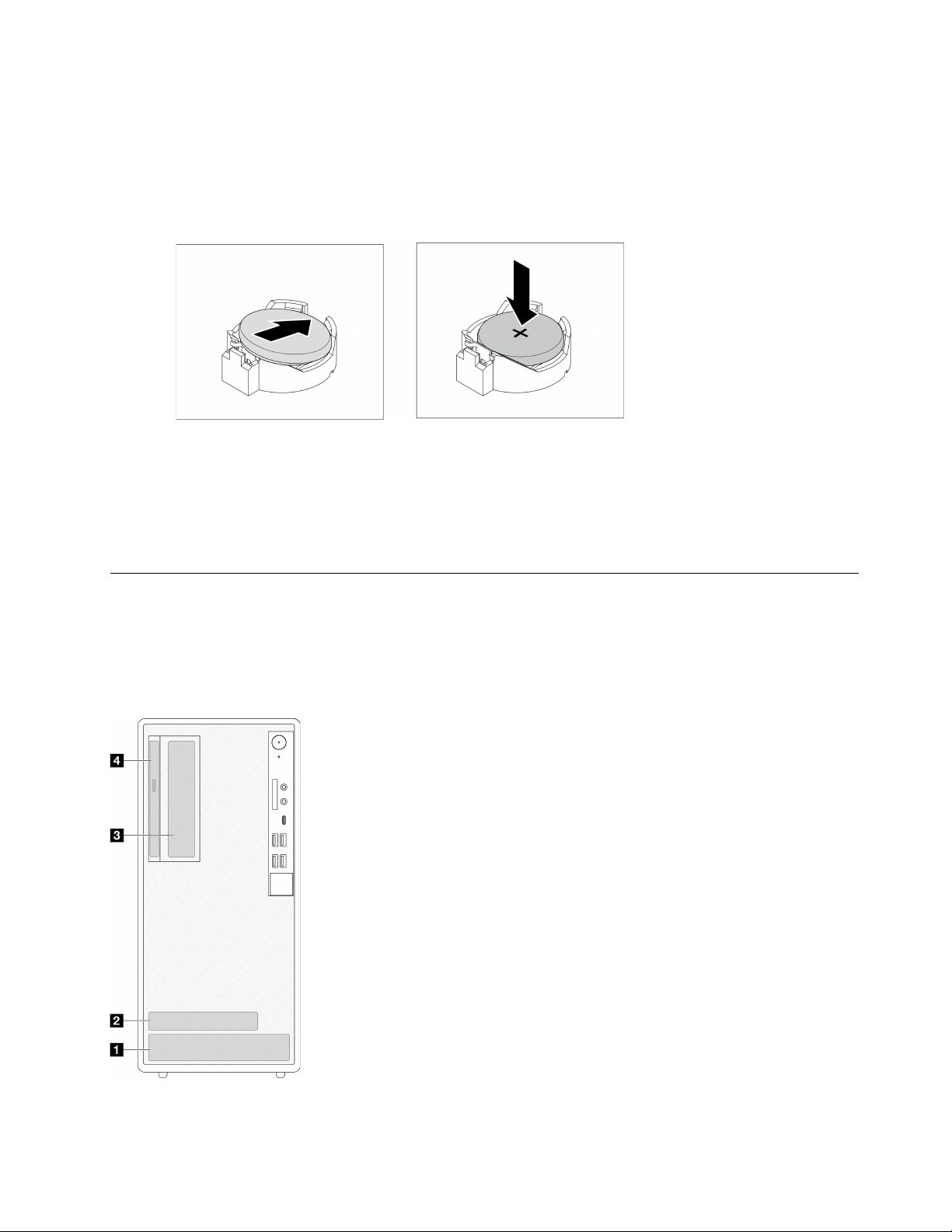
Step 1. Place the CMOS battery on top of the socket with the positive (+) symbol facing up, and press the
battery into the seat until it clicks in place.
Figure 31. Installing the CMOS battery
After you finish
1. Reset date, time, and all the passwords.
2. Proceed to complete the parts replacement, see
“Complete the parts replacement” on page 158.
Drive and drive cage replacement
Follow this procedure to remove and install a drive or a drive cage.
Drive bay locations
See the following illustration for the locations of drive bays and the types of drives supported.
Figure 32. Drive bay locations
Chapter 3. Hardware replacement procedures 49
Drive bay Types of drive supported
1 Bay 1 3.5-inch simple-swap drive
2 Bay 2 2.5-inch simple-swap drive
3 Bay 3 3.5-inch simple-swap drive
4 Optical drive bay 9mm slim SATA Optical disk drive
Simple-swap drive and drive cage (bay 1-2) replacement
Follow this procedure to install a simple-swap drive and drive cage into bay 1 or bay 2.
Remove a simple-swap drive (bay 1-2)
Follow this procedure to remove a simple-swap drive from bay 1 and bay 2.
S002
CAUTION:
The power-control button on the device and the power switch on the power supply do not turn off the
electrical current supplied to the device. The device also might have more than one power cord. To
remove all electrical current from the device, ensure that all power cords are disconnected from the
power source.
About this task
Attention:
• Read
“Safety inspection checklist” on page iv and “Installation guidelines” on page 41 to ensure that you
work safely.
• Turn off the server and peripheral devices, and disconnect the power cords and all external cables, see
“Power off the server” on page 9.
• If the server is in a rack, remove it from the rack. See
“Remove the server from the rails” on page 138.
• Remove any locking device that secures the server, such as a Kensington lock or a padlock.
• Place the server on its side with the cover up.
Watch the procedure
A video of this procedure is available at YouTube:
https://www.youtube.com/playlist?list=PLYV5R7hVcs-
AU3iY3F7lq3qfqr5caGbIu
.
Procedure
Step 1. Make preparation for this task.
a. Remove the server cover, see
“Remove the server cover” on page 144.
Attention: The heat sink and processor could be very hot. To avoid burning yourself, wait for a
few minutes after turning off the server before you remove the server cover.
Step 2. Disconnect every cable from the drive assembly.
50
ThinkSystem ST50 V2 Maintenance Manual
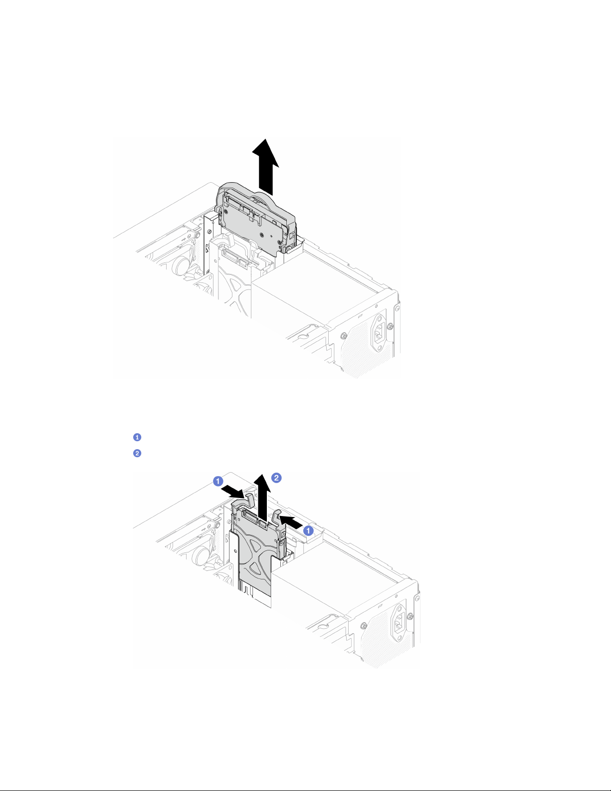
Step 3. Remove the simple-swap drive assembly.
Remove the simple-swap drive assembly from drive bay 1
Grasp the retainer handle, and lift the drive assembly out of the drive bay.
Figure 33. Removing drive assembly from drive bay 1
Remove the simple-swap drive assembly from drive bay 2
a.
Pinch the retainer handles.
b.
Lift the drive assembly out from the drive bay.
Figure 34. Removing drive assembly from drive bay 2
Chapter 3. Hardware replacement procedures 51
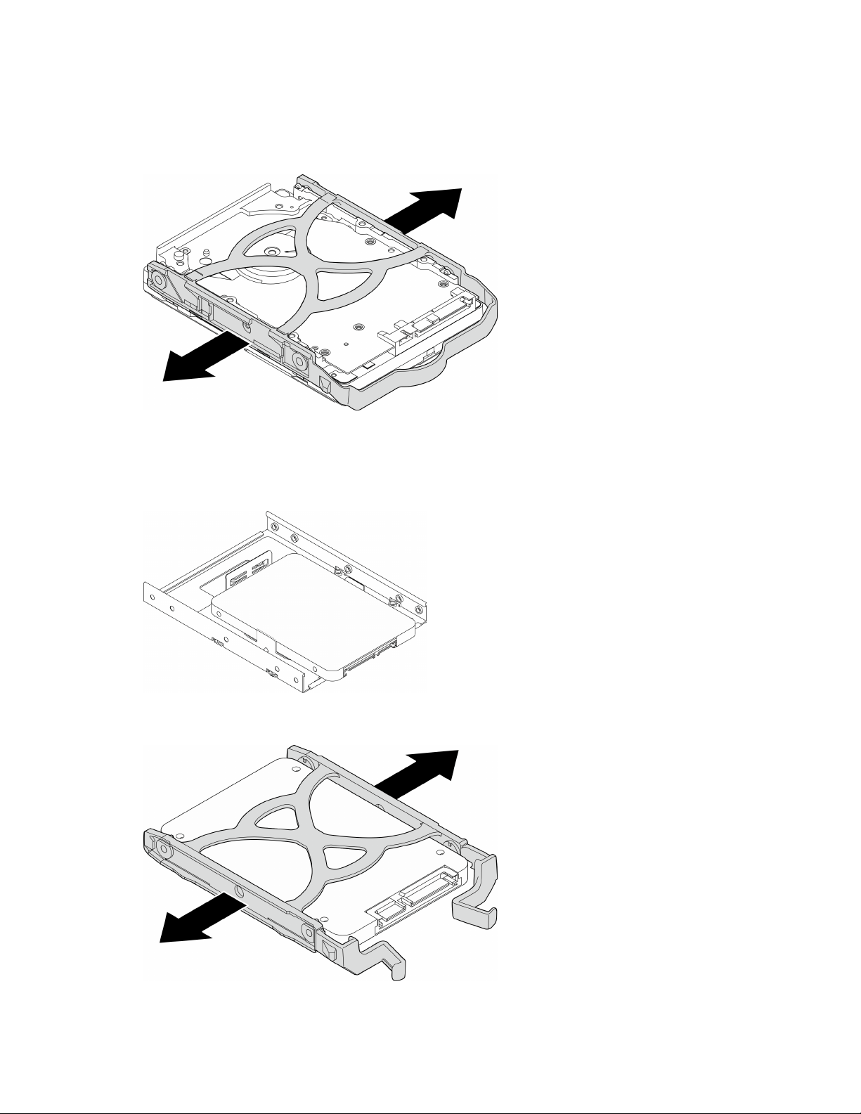
Step 4. If necessary, remove the drive from the retainer. Tear both sides of the retainer apart, and remove
the drive.
Remove a 3.5-inch drive from the retainer
Figure 35. Removing a 3.5-inch drive from the retainer
Note: Depending on the configuration, the 3.5-inch drive may be the model in the illustration
below.
Remove a 2.5-inch drive from the retainer
Figure 36. Removing a 2.5-inch drive from the retainer
52 ThinkSystem ST50 V2 Maintenance Manual
After you finish
1. Install a 3.5-inch drive to drive bay 1 or a 2.5-inch drive to drive bay 2, see
“Install a simple-swap drive
(bay 1-2)” on page 53
.
2. If you are instructed to return the component or optional device, follow all packaging instructions, and
use any packaging materials for shipping that are supplied to you.
Install a simple-swap drive (bay 1-2)
Follow this procedure to install a simple-swap drive to bay 1 or bay 2.
S002
CAUTION:
The power-control button on the device and the power switch on the power supply do not turn off the
electrical current supplied to the device. The device also might have more than one power cord. To
remove all electrical current from the device, ensure that all power cords are disconnected from the
power source.
About this task
Attention:
• Read
“Safety inspection checklist” on page iv and “Installation guidelines” on page 41 to ensure that you
work safely.
• Touch the static-protective package that contains the component to any unpainted metal surface on the
server; then, remove it from the package and place it on a static-protective surface.
• Make sure the type of drives to be installed is supported. Following are the types supported:
– 3.5-inch simple-swap hard-disk drive or solid-state drive in drive bay 1 and drive bay 3
– 2.5-inch simple-swap solid-state drive in drive bay 2
For a complete list of supported optional devices for the server, see
https://static.lenovo.com/us/en/
serverproven/index.shtml
.
• If there are more than one drives to be installed, determine installation order based on the following rules:
– Start with solid-state drives, and proceed with hard-disk drives.
– When installing one 3.5-inch solid-state drive and one 3.5-inch hard-disk drive, install the solid-state
drive in bay 1 and the hard-disk drive in bay 3.
– Start with the drive with the lowest capacity.
– Start with bay 1, proceed to bay 2, and bay 3.
Note: Drives of different types and different capacities are allowed to be installed in one server, but not in
the same RAID array. The drives in a single RAID array must be the same type and the same capacity. See
https://sysmgt.lenovofiles.com/help/topic/LXPML/RAID_setup.html for more details.
Watch the procedure
A video of this procedure is available at YouTube:
https://www.youtube.com/playlist?list=PLYV5R7hVcs-
AU3iY3F7lq3qfqr5caGbIu
.
Chapter 3. Hardware replacement procedures 53
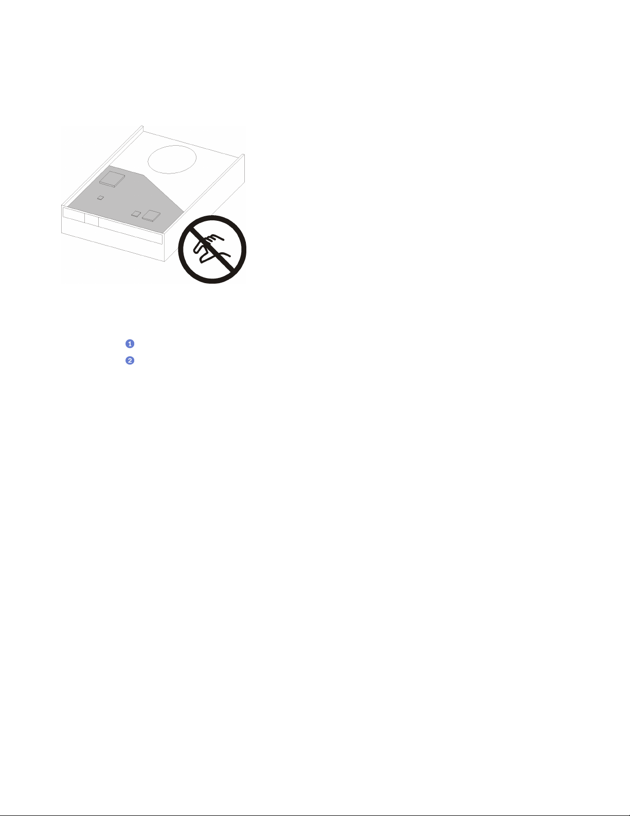
Procedure
Note: To prevent from damaging the drive with static discharge, do not touch the circuit board on the
bottom of the drive.
Figure 37. Circuit board on the drive
Step 1. Install a 3.5-inch or 2.5-inch drive to the retainer
a.
Slightly tear both sides of the retainer apart.
b.
Align the four holes on the drive with the corresponding pins on the retainer; then, fit the
drive into the retainer.
Note: The drive connectors should face the retainer handles.
Install a 3.5-inch drive into the retainer
54
ThinkSystem ST50 V2 Maintenance Manual
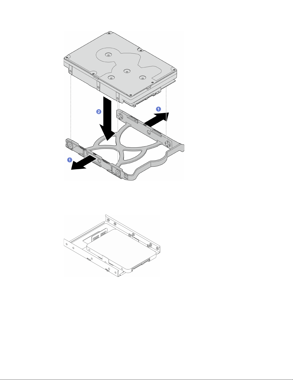
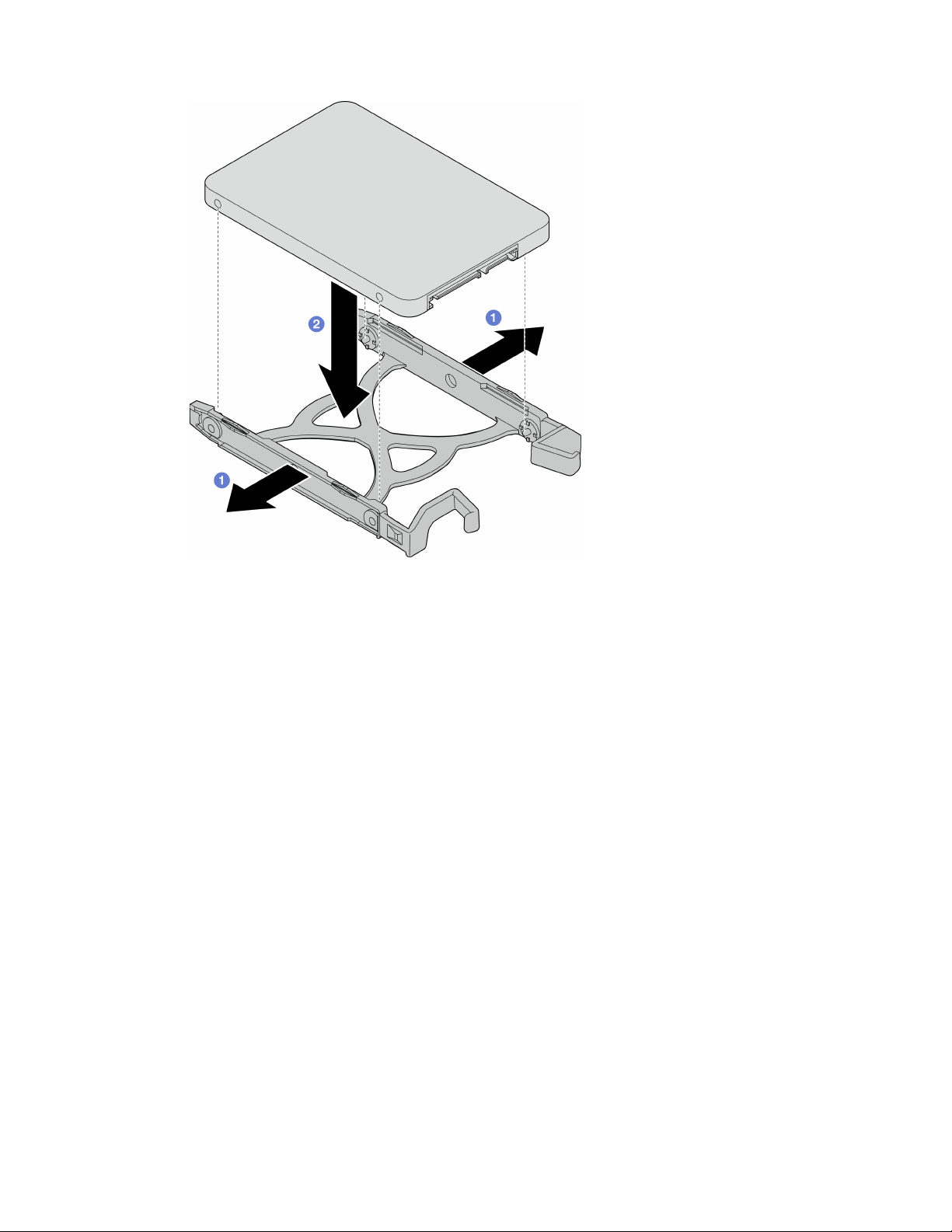
Figure 39. Installing a 2.5-inch drive into the retainer
Step 2. Face the retainer handles upward and push the drive assembly into the drive bay. Press the drive
assembly firmly to ensure it is seated correctly.
Install 3.5-inch drive assembly into drive bay 1
56
ThinkSystem ST50 V2 Maintenance Manual
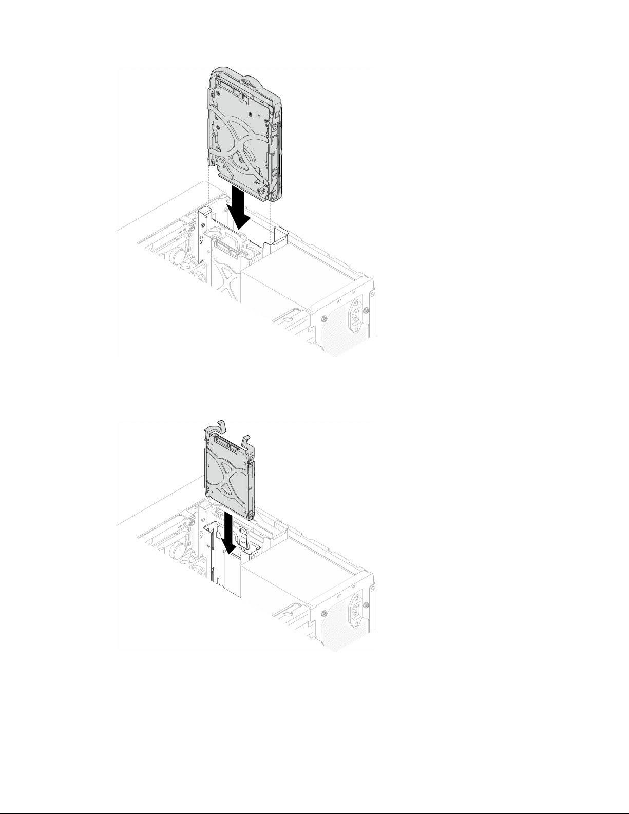
Figure 40. Install 3.5-inch drive assembly into drive bay 1
Install 2.5-inch drive assembly into drive bay 2
Figure 41. Install 2.5-inch drive assembly into drive bay 2
Step 3. Connect the signal and power cable to the system board, see “Internal cable routing” on page 19.
After you finish
1. Complete the parts replacement, see
“Complete the parts replacement” on page 158.
Chapter 3. Hardware replacement procedures 57
2. Check the drive activity LED on the front panel to verify if the drives are operating correctly.
Table 28. Drive activity LED behavior
Status Color Description
Solid on
White The drives are active.
Off
None The drives are not active.
3. Use the Lenovo XClarity Provisioning Manager Lite to configure the RAID if necessary. For more
information, see
https://sysmgt.lenovofiles.com/help/topic/LXPML/RAID_setup.html.
Remove the drive cage (bay 1-2)
Follow this procedure to remove the drive cage from bay 1 or bay 2.
S002
CAUTION:
The power-control button on the device and the power switch on the power supply do not turn off the
electrical current supplied to the device. The device also might have more than one power cord. To
remove all electrical current from the device, ensure that all power cords are disconnected from the
power source.
About this task
Attention:
• Read
“Safety inspection checklist” on page iv and “Installation guidelines” on page 41 to ensure that you
work safely.
• Turn off the server and peripheral devices, and disconnect the power cords and all external cables, see
“Power off the server” on page 9.
• If the server is in a rack, remove it from the rack. See
“Remove the server from the rails” on page 138.
• Remove any locking device that secures the server, such as a Kensington lock or a padlock.
• Place the server on its side with the cover up.
Watch the procedure
A video of this procedure is available at YouTube:
https://www.youtube.com/playlist?list=PLYV5R7hVcs-
AU3iY3F7lq3qfqr5caGbIu
.
Procedure
Step 1. Make preparation for this task.
a. Remove the server cover. See
“Remove the server cover” on page 144.
Attention: The heat sinks and processor could be very hot. To avoid burning yourself, wait for
a few minutes after turning off the server before you remove the server cover.
b. Remove the simple-wasp drive from drive bay 1 or drive bay 2, see “Remove a simple-swap
drive (bay 1-2)” on page 50.
Step 2. Remove the bay 2 drive cage.
58
ThinkSystem ST50 V2 Maintenance Manual
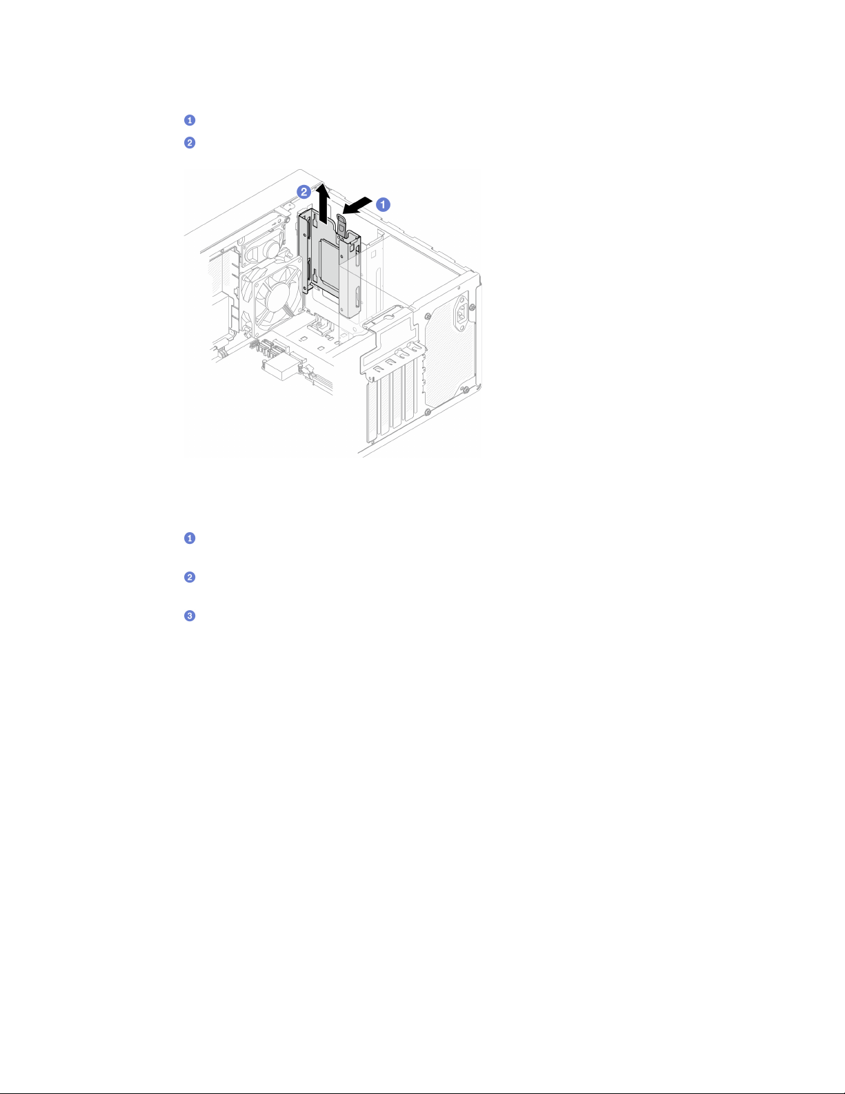
Note: Remove the bay 2 drive cage first; then, proceed to remove the bay 1 drive cage.
a.
Slightly pull out the latch on the bay 2 drive cage to release it from the bay 1 drive cage.
b.
Pull the bay 2 drive cage out from the chassis.
Figure 42. Removing drive cage from drive bay 2
Step 3. Remove the bay 1 drive cage.
a.
From outside of the chassis, remove the screw that secures the bay 1 drive cage to the
chassis.
b.
From inside of the chassis, remove the screw that secures the bay 1 drive cage to the
chassis.
c.
Pull the bay 1 drive cage out from the chassis.
Chapter 3. Hardware replacement procedures 59
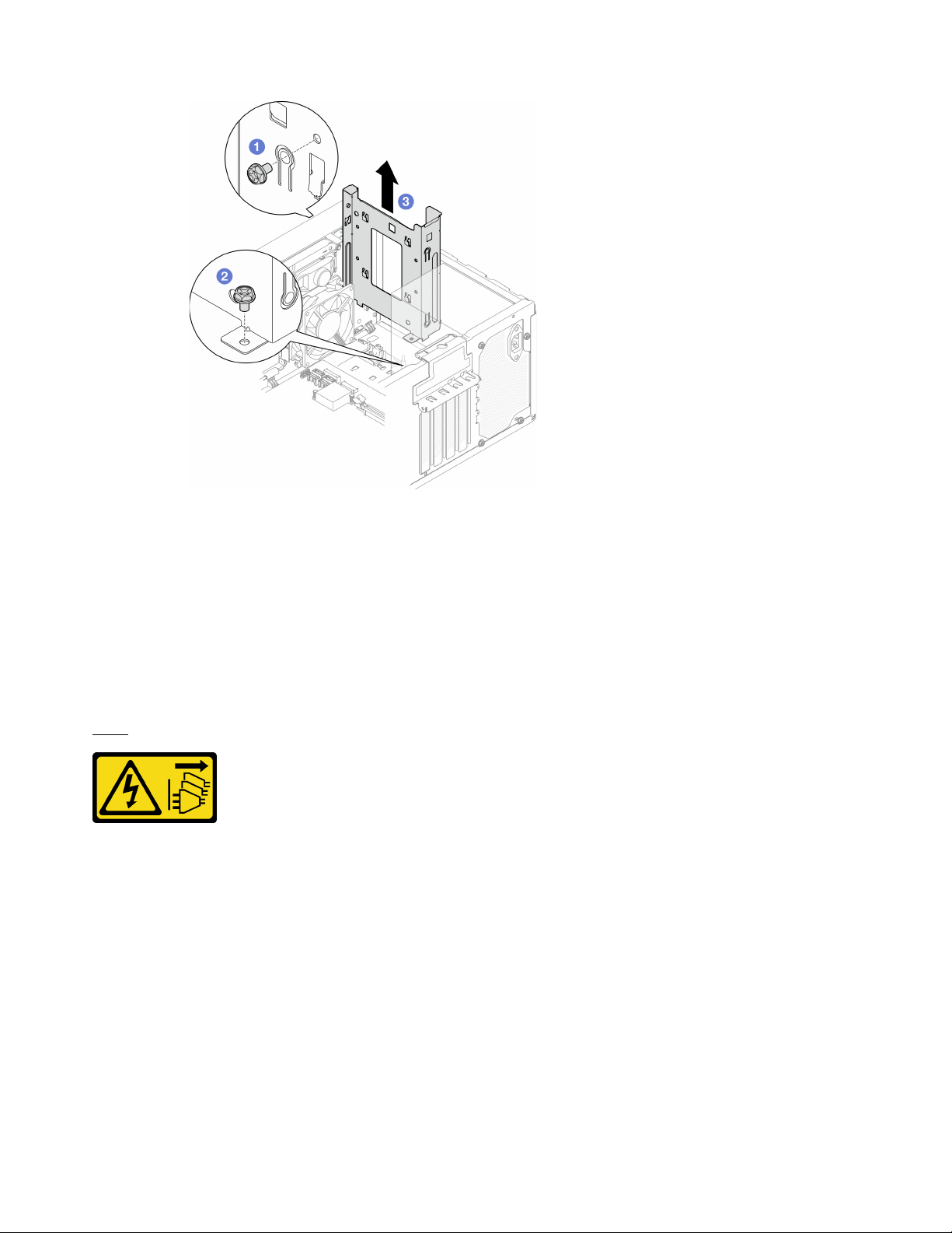
Figure 43. Removing drive cage from drive bay 1
After you finish
1. Install a new drive cage, see
“Install the drive cage (bay 1-2)” on page 60.
2. If you are instructed to return the component or optional device, follow all packaging instructions, and
use any packaging materials for shipping that are supplied to you.
Install the drive cage (bay 1-2)
Follow this procedure to install the bay 1 drive cage bay 2 drive cage.
S002
CAUTION:
The power-control button on the device and the power switch on the power supply do not turn off the
electrical current supplied to the device. The device also might have more than one power cord. To
remove all electrical current from the device, ensure that all power cords are disconnected from the
power source.
About this task
Attention:
• Read
“Safety inspection checklist” on page iv and “Installation guidelines” on page 41 to ensure that you
work safely.
Watch the procedure
60
ThinkSystem ST50 V2 Maintenance Manual
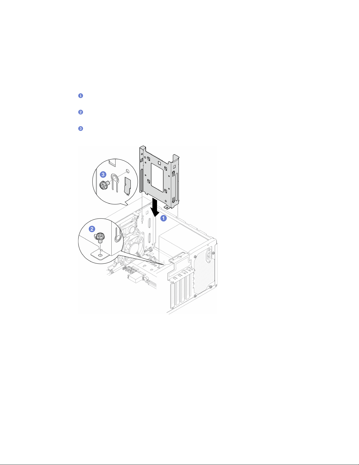
A video of this procedure is available at YouTube: https://www.youtube.com/playlist?list=PLYV5R7hVcs-
AU3iY3F7lq3qfqr5caGbIu
.
Procedure
Note: Install the bay 1 drive cage first; then, proceed to install the bay 2 drive cage.
Step 1. Install the bay 1 drive cage.
a.
Align the bay 1 drive cage to the slots on chassis; then, install it into the chassis. Make sure
the drive cage is seated correctly in the chassis.
b.
From the inside of the chassis, fasten the screw that secures the bay 1 drive cage to the
chassis.
c.
From the outside of the chassis, fasten the screw that secures the bay 1 drive cage to the
chassis.
Figure 44. Installing drive cage to bay 1
Step 2. Install the bay 2 drive cage.
Align the four hooks on both drive cages, and attache bay 2 drive cage to bay 1 drive cage; then,
slide the bay 2 drive cage downward until the four hooks on both drive cages are fully engaged.
Make sure the latch on the bay 2 drive cage is also engaged with the hook on bay 1 drive cage.
Chapter 3. Hardware replacement procedures 61
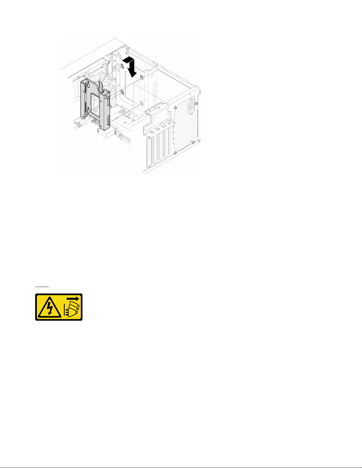
Figure 45. Installing the drive bay 2 cage
After you finish
1. Install simple-swap drives if necessary, see
“Install a simple-swap drive (bay 1-2)” on page 53.
2. Complete the parts replacement, see
“Complete the parts replacement” on page 158.
Simple-swap drive and drive cage replacement (bay 3)
Follow this procedure to remove and install a simple-swap drive or drive cage from and into bay 3.
Remove a simple-swap drive (bay 3)
Follow this procedure to remove a simple-swap drive from bay 3.
S002
CAUTION:
The power-control button on the device and the power switch on the power supply do not turn off the
electrical current supplied to the device. The device also might have more than one power cord. To
remove all electrical current from the device, ensure that all power cords are disconnected from the
power source.
About this task
Attention:
• Read
“Safety inspection checklist” on page iv and “Installation guidelines” on page 41 to ensure that you
work safely.
• Turn off the server and peripheral devices, and disconnect the power cords and all external cables, see
“Power off the server” on page 9.
62
ThinkSystem ST50 V2 Maintenance Manual
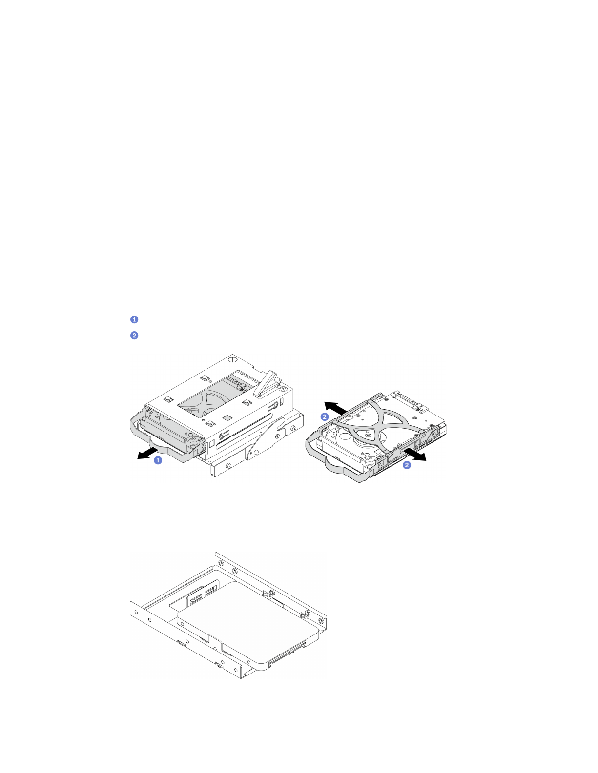
• If the server is in a rack, remove it from the rack. See “Remove the server from the rails” on page 138.
• Remove any locking device that secures the server, such as a Kensington lock or a padlock.
• Place the server on its side with the cover up.
Watch the procedure
A video of this procedure is available at YouTube:
https://www.youtube.com/playlist?list=PLYV5R7hVcs-
AU3iY3F7lq3qfqr5caGbIu
.
Procedure
Step 1. Make preparation for this task.
a. Remove the server cover, see
“Remove the server cover” on page 144.
Note: The heat sink and processor could be very hot. To avoid burning yourself, wait for a few
minutes after turning off the server before you remove the server cover.
b. If applicable, remove the optical drive, see
“Remove an optical drive” on page 70.
c. Remove the optical drive cage from the chassis, see
“Remove the optical drive cage” on page
76
.
Step 2. Remove the 3.5-inch drive.
a.
Slide the drive retainer out from the drive cage.
b.
Tear both sides of the retainer apart and remove the drive from the retainer.
Figure 46. Removing the 3.5-inch drive
Note: Depending on the configuration, the 3.5-inch drive may be the model in the illustration
below.
After you finish
Chapter 3. Hardware replacement procedures 63
1. Install a new 3.5-inch drive, see “Install a simple-swap drive (bay 3)” on page 64.
2. If you are instructed to return the component or optional device, follow all packaging instructions, and
use any packaging materials for shipping that are supplied to you.
Install a simple-swap drive (bay 3)
Follow this procedure to install a simple-swap drive to bay 3.
S002
CAUTION:
The power-control button on the device and the power switch on the power supply do not turn off the
electrical current supplied to the device. The device also might have more than one power cord. To
remove all electrical current from the device, ensure that all power cords are disconnected from the
power source.
About this task
Attention:
• Read
“Safety inspection checklist” on page iv and “Installation guidelines” on page 41 to ensure that you
work safely.
• Touch the static-protective package that contains the component to any unpainted metal surface on the
server; then, remove it from the package and place it on a static-protective surface.
• Make sure the type of drives to be installed is supported. Following are the types supported:
– 3.5-inch simple-swap hard-disk drive or solid-state drive in drive bay 1 and drive bay 3
– 2.5-inch simple-swap solid-state drive in drive bay 2
For a complete list of supported optional devices for the server, see
https://static.lenovo.com/us/en/
serverproven/index.shtml
.
• If there are more than one drives to be installed, determine installation order based on the following rules:
– Start with solid-state drives, and proceed with hard-disk drives.
– When installing one 3.5-inch solid-state drive and one 3.5-inch hard-disk drive, install the solid-state
drive in bay 1 and the hard-disk drive in bay 3.
– Start with the drive with the lowest capacity.
– Start with bay 1, proceed to bay 2, and bay 3.
Note: Drives of different types and different capacities are allowed to be installed in one server, but not in
the same RAID array. The drives in a single RAID array must be the same type and the same capacity. See
https://sysmgt.lenovofiles.com/help/topic/LXPML/RAID_setup.html for more details.
Watch the procedure
A video of this procedure is available at YouTube:
https://www.youtube.com/playlist?list=PLYV5R7hVcs-
AU3iY3F7lq3qfqr5caGbIu
.
Procedure
64 ThinkSystem ST50 V2 Maintenance Manual
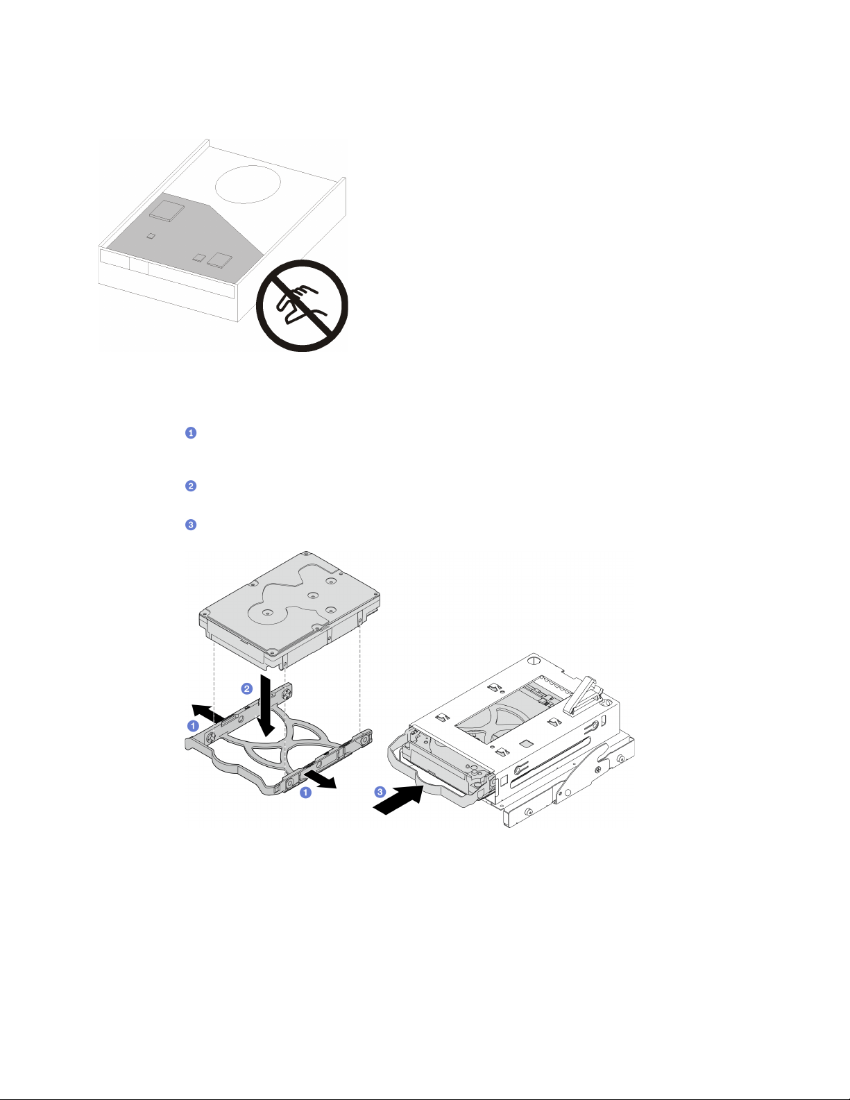
Note: To prevent from damaging the drive with static discharge, do not touch the circuit board on the
bottom of the drive.
Figure 47. Circuit board on the drive
Step 1. Install the 3.5-inch drive to the drive cage.
a.
Slightly tear both sides of the retainer apart.
Attention: Position the drive connectors on the opposite side of the retainer handles.
b.
Align the four holes on the drive with the corresponding pins on the retainer; then, fit the
drive into the retainer.
c.
Slide the drive into the drive cage.
Figure 48. Installing a 3.5-inch drive to the drive cage
Attention: If you are installing a 3.5-inch drive as the model in the illustration below:
Chapter 3. Hardware replacement procedures 65
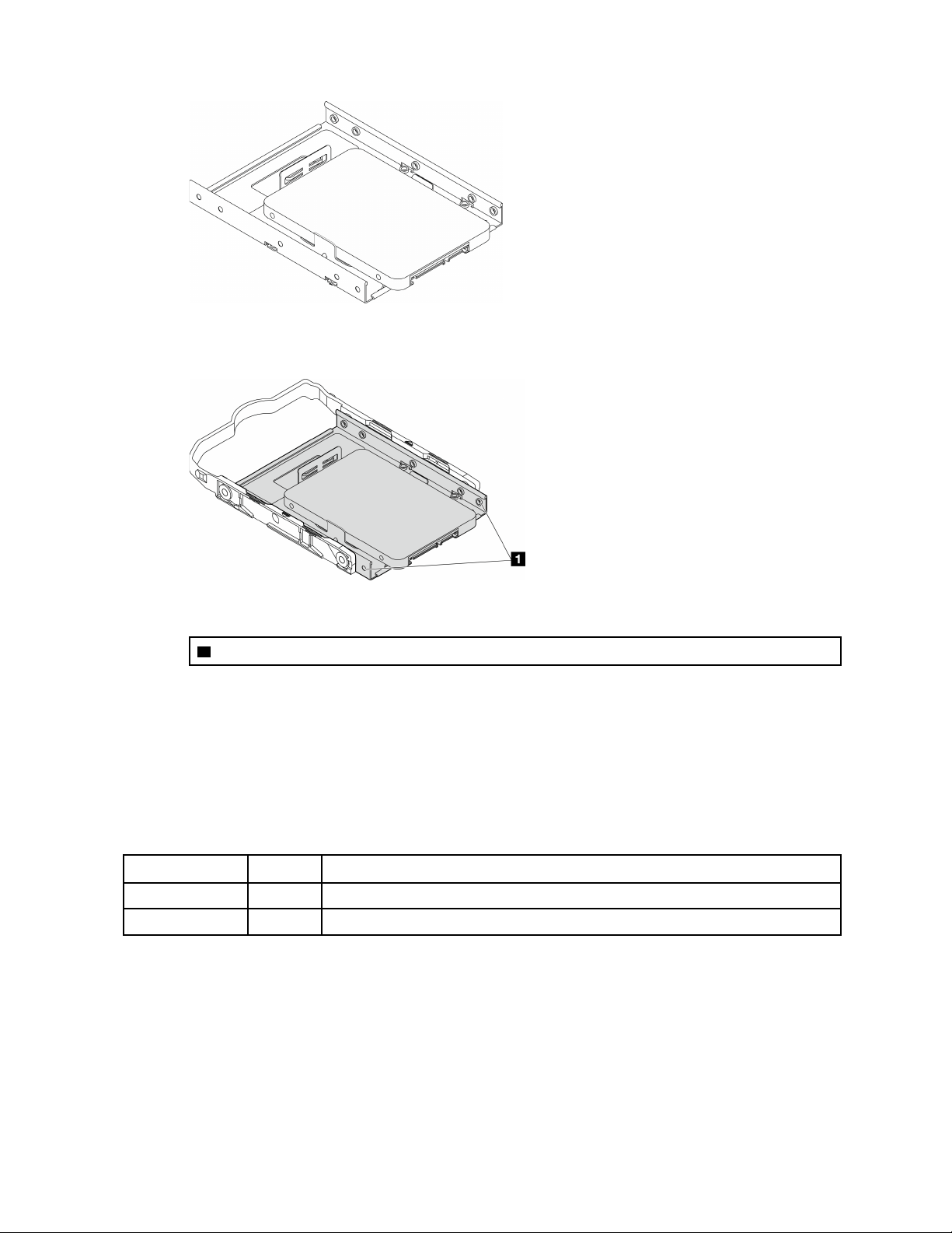
Make sure the screw holes that are nearest to the drive connector are outside of the drive
retainer.
Figure 49. Drive screw hole placement on retainer
1 Screw holes nearest to the drive connector
After you finish
1. Install the optical drive cage, see “Install the optical drive cage” on page 78.
2. Connect the signal and power cable to the system board, see
“Internal cable routing” on page 19.
3. Complete the parts replacement, see
“Complete the parts replacement” on page 158.
4. Check the drive activity LED on the front panel to verify if the drives are operating correctly.
Table 29. Drive activity LED behavior
Status Color
Description
Solid on White The drives are active.
Off None The drives are not active.
5. Use the Lenovo XClarity Provisioning Manager Lite to configure the RAID if necessary. For more
information, see
https://sysmgt.lenovofiles.com/help/topic/LXPML/RAID_setup.html.
Remove the drive cage (bay 3)
Follow this procedure to remove a simple-swap drive cage from bay 3.
66
ThinkSystem ST50 V2 Maintenance Manual

S002
CAUTION:
The power-control button on the device and the power switch on the power supply do not turn off the
electrical current supplied to the device. The device also might have more than one power cord. To
remove all electrical current from the device, ensure that all power cords are disconnected from the
power source.
About this task
Attention:
• Read
“Safety inspection checklist” on page iv and “Installation guidelines” on page 41 to ensure that you
work safely.
• Turn off the server and peripheral devices, and disconnect the power cords and all external cables, see
“Power off the server” on page 9.
• If the server is in a rack, remove it from the rack. See
“Remove the server from the rails” on page 138.
• Remove any locking device that secures the server, such as a Kensington lock or a padlock.
• Place the server on its side with the cover up.
Watch the procedure
A video of this procedure is available at YouTube:
https://www.youtube.com/playlist?list=PLYV5R7hVcs-
AU3iY3F7lq3qfqr5caGbIu
.
Procedure
Step 1. Make preparation for this task.
a. Remove the server cover, see
“Remove the server cover” on page 144.
Note: The heat sink and processor could be very hot. To avoid burning yourself, wait for a few
minutes after turning off the server before you remove the server cover.
b. If applicable, remove the optical drive, see
“Remove an optical drive” on page 70.
c. Remove the optical drive cage, see
“Remove the optical drive cage” on page 76.
d. If applicable, remove the 3.5-inch drive from the 3.5-inch drive cage, see
“Remove a simple-
swap drive (bay 3)” on page 62
.
Chapter 3. Hardware replacement procedures 67
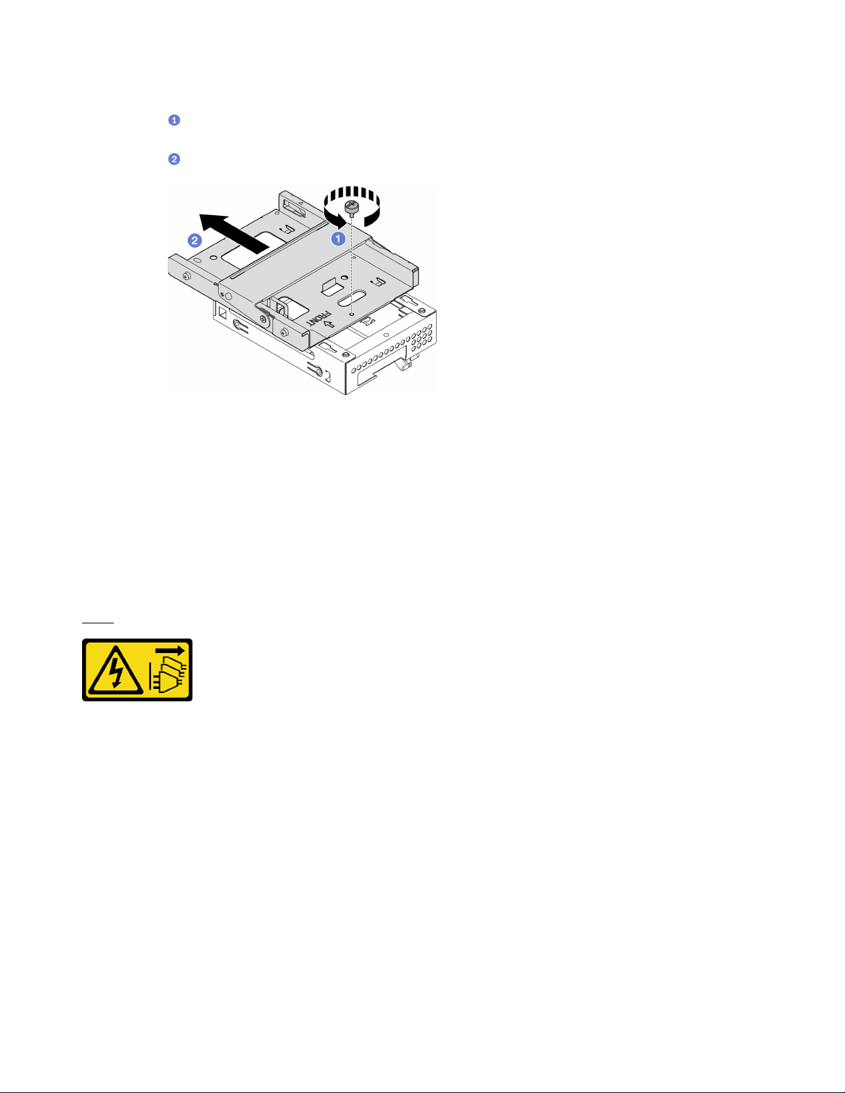
Step 2. Remove the 3.5-inch drive cage from the optical drive cage.
a.
Remove the screw that secures the 3.5-inch drive cage to the optical drive cage. Reserve
the screw to be used for reinstalling the 3.5-inch drive cage..
b.
Slide the optical drive cage to separate it from the 3.5-inch drive cage.
Figure 50. Removing the 3.5-inch drive cage from the optical drive cage
After you finish
1. Install a new 3.5-inch drive cage, see
“Install the drive cage (bay 3)” on page 68.
2. If you are instructed to return the component or optional device, follow all packaging instructions, and
use any packaging materials for shipping that are supplied to you.
Install the drive cage (bay 3)
Follow this procedure to install the drive cage to bay 3.
S002
CAUTION:
The power-control button on the device and the power switch on the power supply do not turn off the
electrical current supplied to the device. The device also might have more than one power cord. To
remove all electrical current from the device, ensure that all power cords are disconnected from the
power source.
About this task
Attention:
• Read
“Safety inspection checklist” on page iv and “Installation guidelines” on page 41 to ensure that you
work safely.
• Touch the static-protective package that contains the component to any unpainted metal surface on the
server; then, remove it from the package and place it on a static-protective surface.
Watch the procedure
68
ThinkSystem ST50 V2 Maintenance Manual
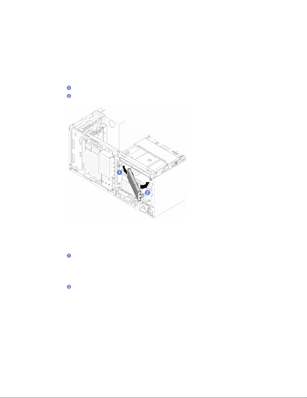
A video of this procedure is available at YouTube: https://www.youtube.com/playlist?list=PLYV5R7hVcs-
AU3iY3F7lq3qfqr5caGbIu
.
Procedure
Step 1. (Optional) Install the EMI shielding included in the component packaging to the chassis.
Note: Installing the EMI shielding is required when the original shielding slot on the chassis is
vacant.
a.
Insert the tabs on the left end of the EMI shielding into the shield slot on the chassis.
b.
Push the EMI shielding into the chassis until it snaps into place.
Figure 51. Installing the EMI shielding
Step 2. Make sure there is no optical drive installed on the optical drive cage. Then, istall the 3.5-inch drive
cage to the optical drive cage.
a.
Align the four hooks on the optical drive cage with the corresponding hooks on the 3.5-inch
drive cage; then, lower the optical drive cage onto the 3.5-inch drive cage, and slide the optical
drive forward until it secures into place.
Note: Make sure the four hooks on both drive cages are fully engaged.
b.
Fasten the captive screw to secure the two drive cages together.
Chapter 3. Hardware replacement procedures 69
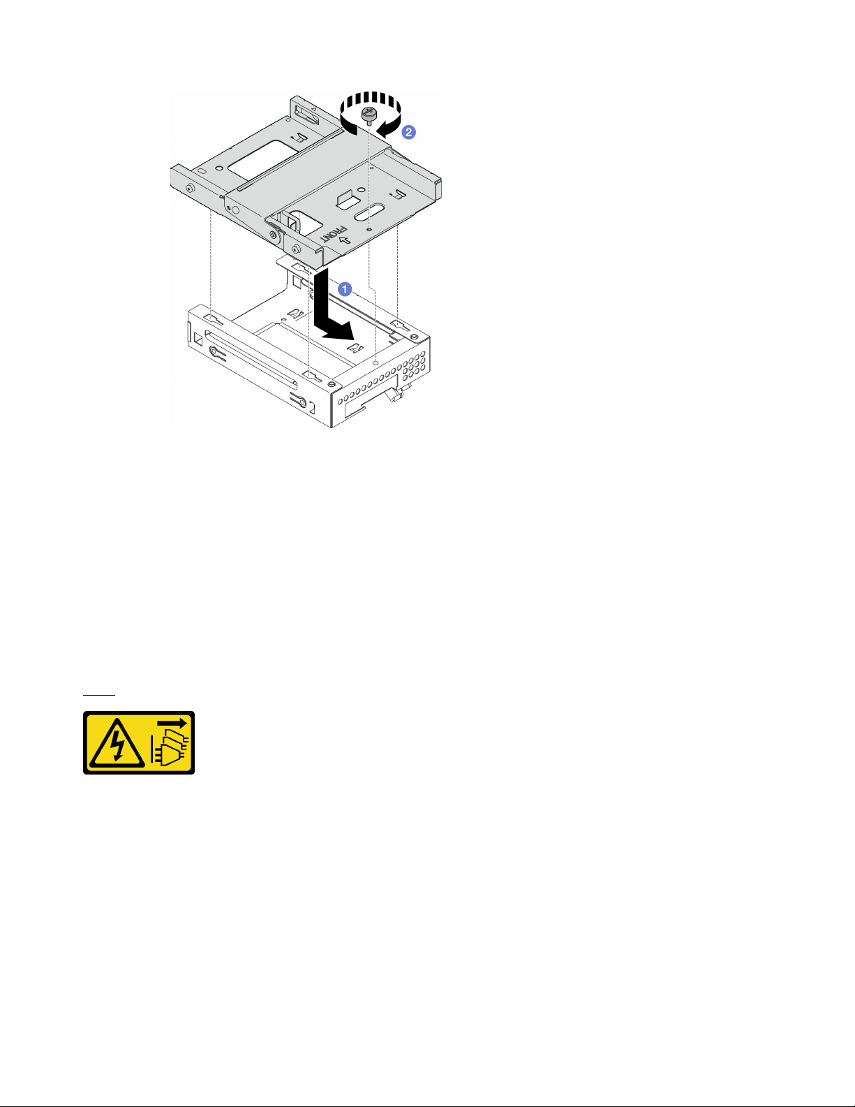
Figure 52. Installing the 3.5-inch drive cage to the optical drive cage
After you finish
1. Reinstall the optical drive cage, see
“Install the optical drive cage” on page 78.
2. Complete the parts replacement, see
“Complete the parts replacement” on page 158.
Optical drive and drive cage replacement
Follow this procedure to remove and install an optical drive and optical drive cage.
Remove an optical drive
Follow this procedure to remove an optical drive.
S002
CAUTION:
The power-control button on the device and the power switch on the power supply do not turn off the
electrical current supplied to the device. The device also might have more than one power cord. To
remove all electrical current from the device, ensure that all power cords are disconnected from the
power source.
About this task
Attention:
• Read
“Safety inspection checklist” on page iv and “Installation guidelines” on page 41 to ensure that you
work safely.
70
ThinkSystem ST50 V2 Maintenance Manual
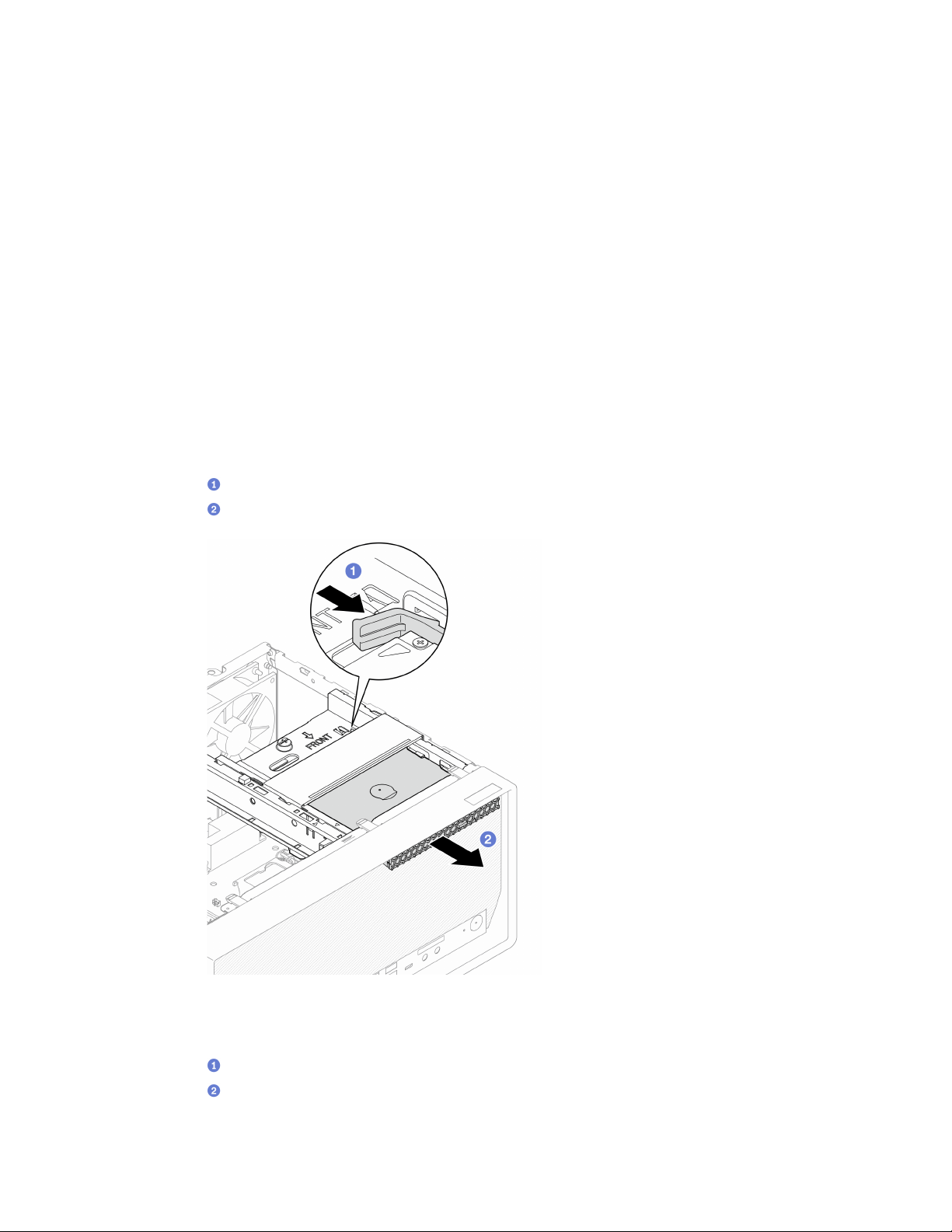
• Turn off the server and peripheral devices, and disconnect the power cords and all external cables, see
“Power off the server” on page 9.
• If the server is in a rack, remove it from the rack. See
“Remove the server from the rails” on page 138.
• Remove any locking device that secures the server, such as a Kensington lock or a padlock.
• Place the server on its side with the cover up.
Watch the procedure
A video of this procedure is available at YouTube:
https://www.youtube.com/playlist?list=PLYV5R7hVcs-
AU3iY3F7lq3qfqr5caGbIu
.
Procedure
Step 1. Make preparation for this task.
a. Remove the server cover, see
“Remove the server cover” on page 144.
Note: The heat sink and processor could be very hot. To avoid burning yourself, wait for a few
minutes after turning off the server before you remove the server cover.
Step 2. Remove the optical drive from the optical drive cage.
a.
Press the latch on the optical drive to release it from the optical drive cage.
b.
Slide out the optical drive from the chassis.
Figure 53. Removing the optical drive
Step 3. (Optional) Remove the optical drive retainer.
a.
Pull out the retainer to disengage it from the optical drive.
b.
Slide the retainer downward, and remove it from the optical drive.
Chapter 3. Hardware replacement procedures 71
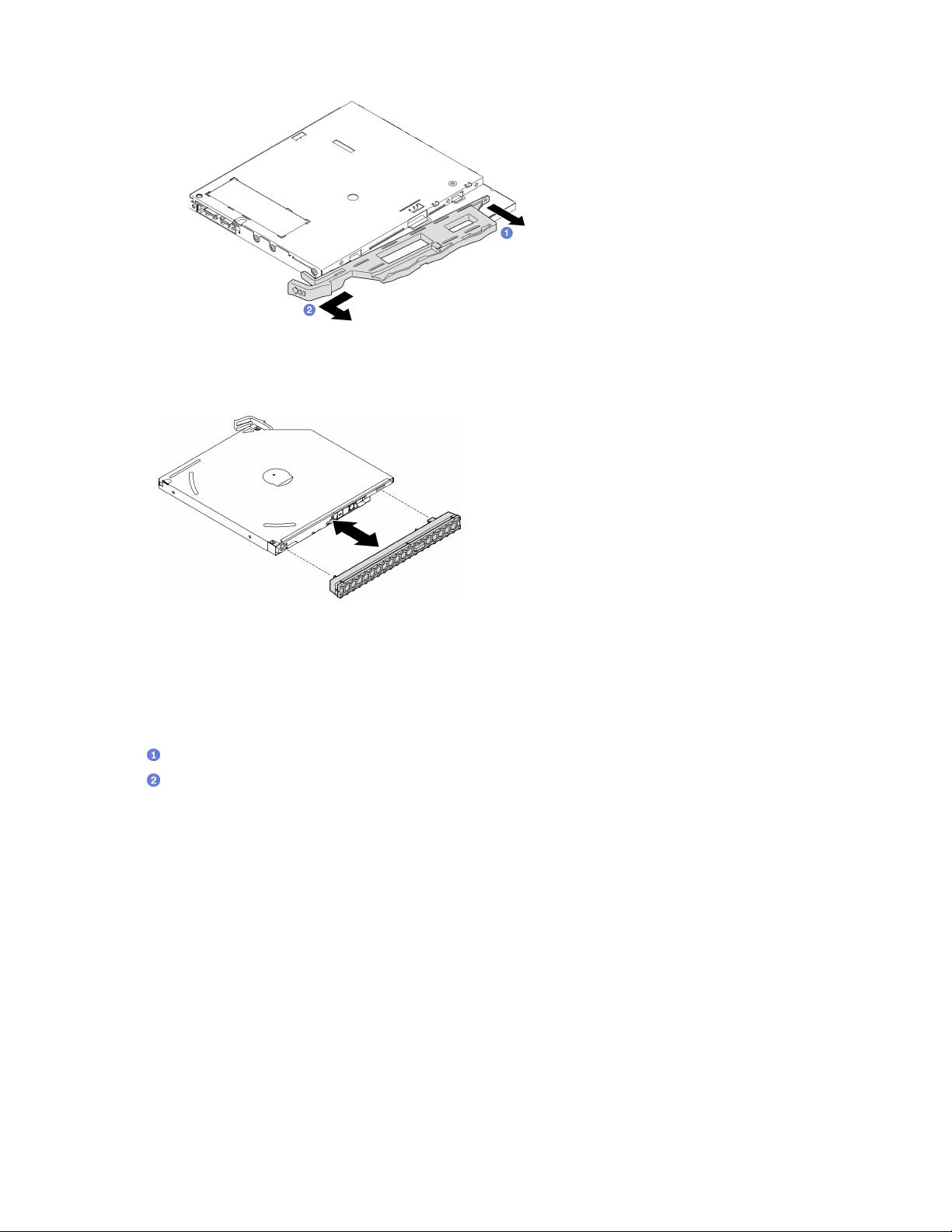
Figure 54. Removing optical drive retainer
Step 4. (Optional) Pull the optical drive bezel away to remove it from the optical drive.
Figure 55. Removing the optical drive bezel
After you finish
1. Install a new optical drive, see
“Install an optical drive” on page 73
2. If no optical drive is to be installed, install the optical drive bay shield back to front bezel.
a.
Engage the bottom of the shield to the opening on the front bezel.
b.
Pivot the shield towards the front bezel until it snaps into place.
72
ThinkSystem ST50 V2 Maintenance Manual
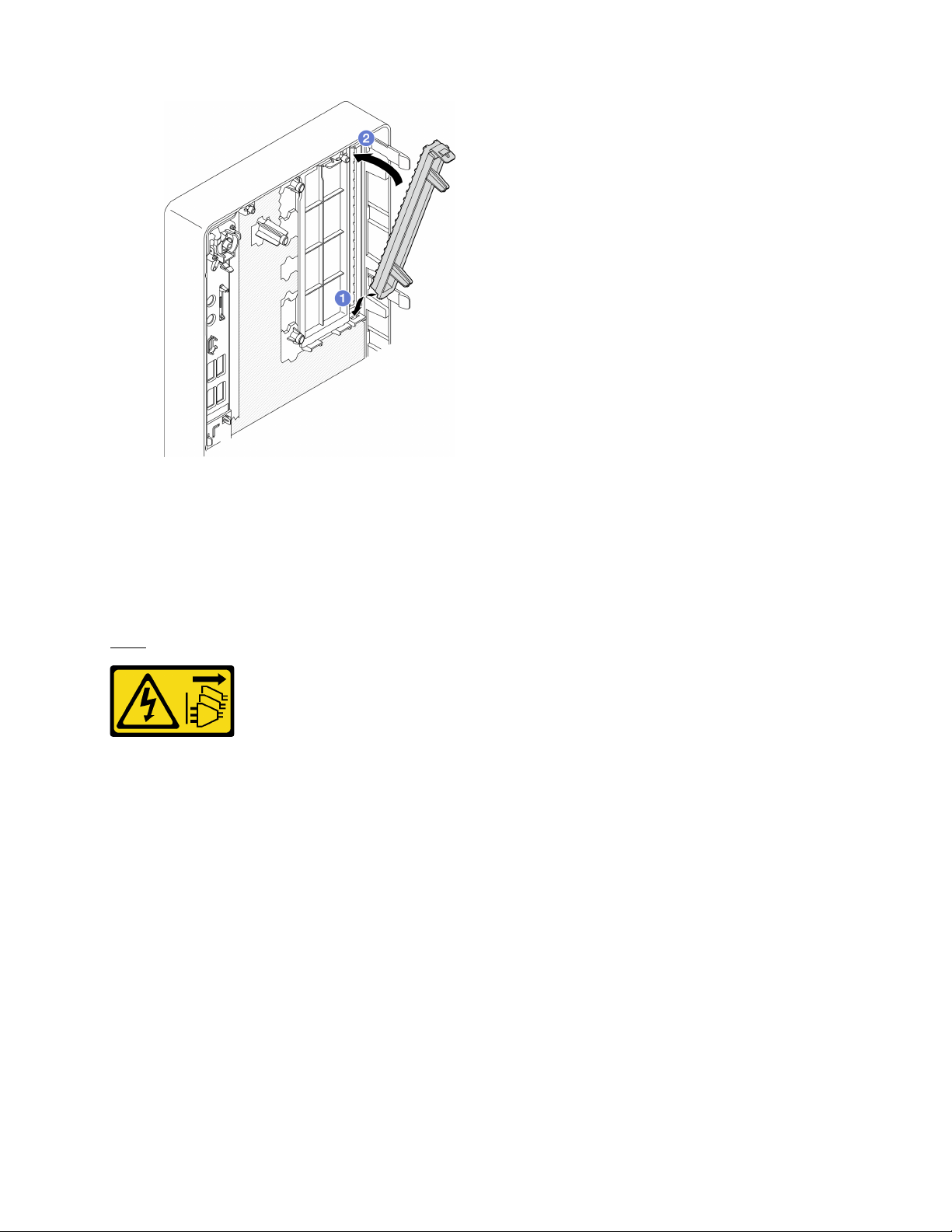
Figure 56. Installing the optical drive bay shield
3. If you are instructed to return the component or optional device, follow all packaging instructions, and
use any packaging materials for shipping that are supplied to you.
Install an optical drive
Follow this procedure to install an optical drive.
S002
CAUTION:
The power-control button on the device and the power switch on the power supply do not turn off the
electrical current supplied to the device. The device also might have more than one power cord. To
remove all electrical current from the device, ensure that all power cords are disconnected from the
power source.
Chapter 3. Hardware replacement procedures 73

S006
CAUTION:
When laser products (such as CD-ROMs, DVD drives, fiber optic devices, or transmitters) are
installed, note the following:
• Do not remove the covers. Removing the covers of the laser product could result in exposure to
hazardous laser radiation. There are no serviceable parts inside the device.
• Use of controls or adjustments or performance of procedures other than those specified herein
might result in hazardous radiation exposure.
About this task
Attention:
• Read
“Safety inspection checklist” on page iv and “Installation guidelines” on page 41 to ensure that you
work safely.
• Touch the static-protective package that contains the component to any unpainted metal surface on the
server; then, remove it from the package and place it on a static-protective surface.
Watch the procedure
A video of this procedure is available at YouTube:
https://www.youtube.com/playlist?list=PLYV5R7hVcs-
AU3iY3F7lq3qfqr5caGbIu
.
Procedure
Step 1. If the optical drive bay shield is installed on the front bezel, remove it from the front bezel. To
remove the front bezel, see
“Remove the front bezel” on page 84.
a.
Press the release tab on top of the drive bay shield.
b.
Rotate the drive bay shield and remove it from the front bezel.
74
ThinkSystem ST50 V2 Maintenance Manual
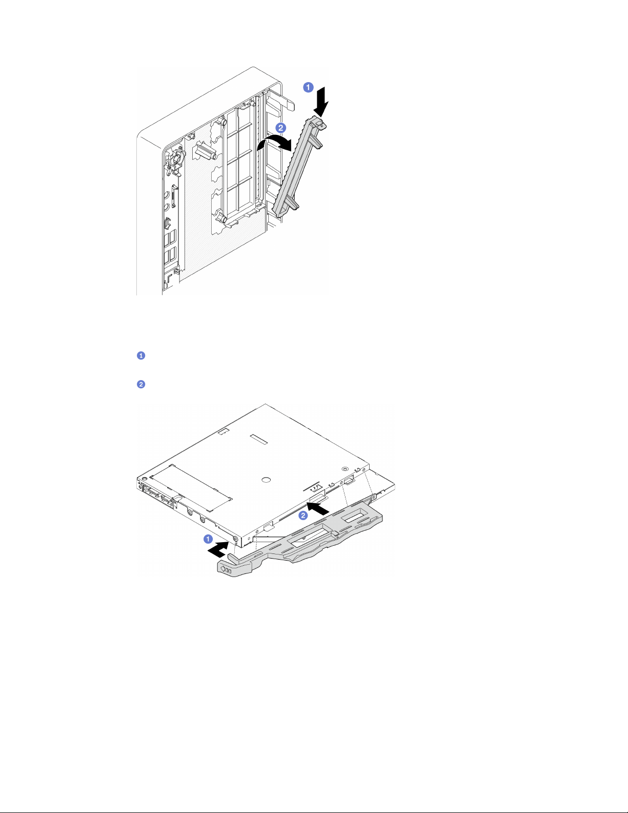
Figure 57. Removing the optical drive bay shield
Step 2. (Optional) Install the optical drive retainer.
a.
Align the pin on the bottom of the retainer and the corresponding slot on the optical drive,
then insert the pin into the slot.
b.
Insert the rest two pins on retainer to the corresponding slots on the optical drive.
Figure 58. Installing the retainer to the optical drive
Step 3. (Optional) Align the optical drive bezel with the slots on the optical drive; then, insert the bezel into
the optical drive.
Chapter 3. Hardware replacement procedures 75
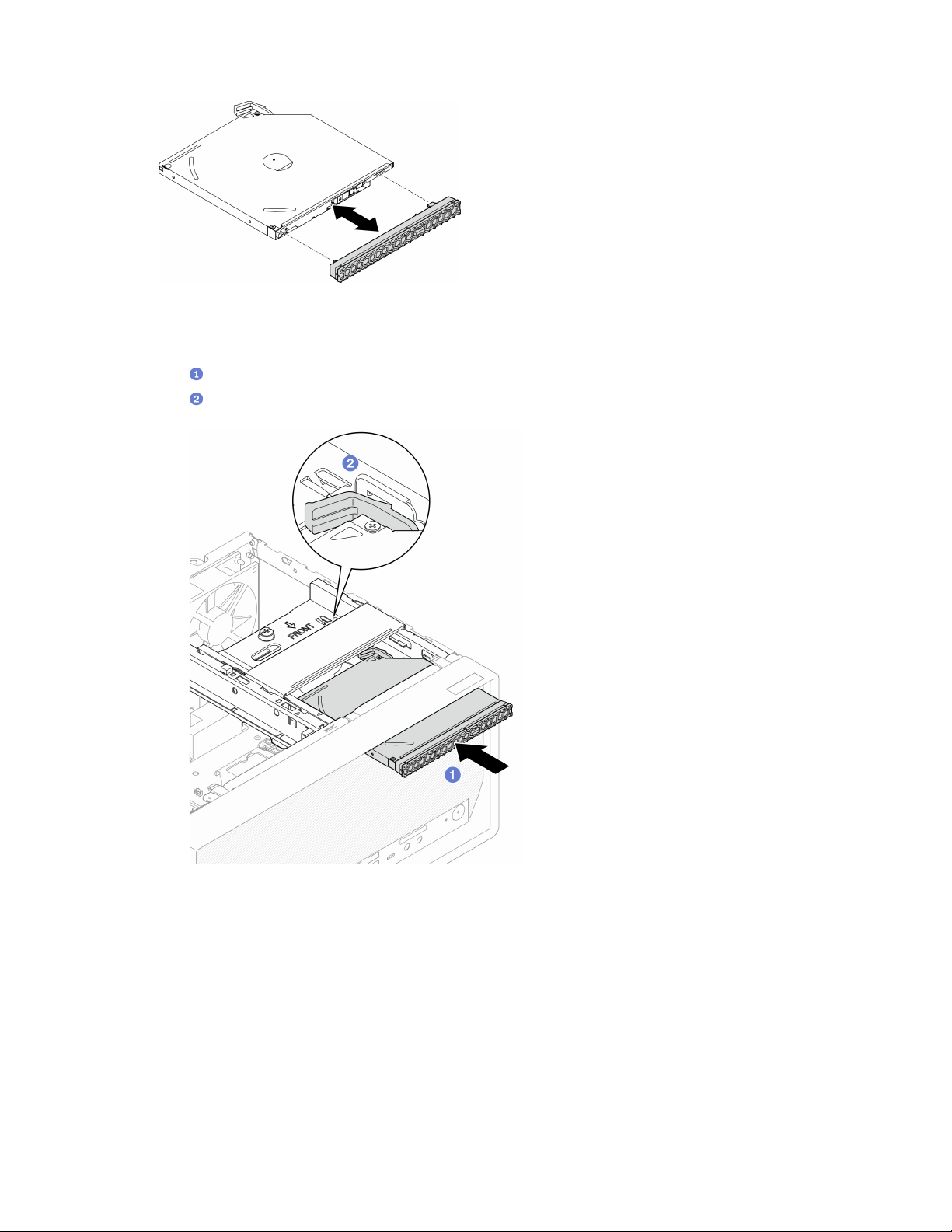
Figure 59. Installing the optical drive bezel
Step 4. Install the optical drive.
a.
From outside of the chassis, insert the optical drive into the chassis.
b.
Slide the optical drive inward until the latch snaps into place.
Figure 60. Installing the optical drive
Step 5. Connect the signal and power cable to the system board, see
“Internal cable routing” on page 19.
After you finish
1. Proceed to complete the parts replacement, see “Complete the parts replacement” on page 158.
Remove the optical drive cage
Follow this procedure to remove the optical drive cage.
76
ThinkSystem ST50 V2 Maintenance Manual

S002
CAUTION:
The power-control button on the device and the power switch on the power supply do not turn off the
electrical current supplied to the device. The device also might have more than one power cord. To
remove all electrical current from the device, ensure that all power cords are disconnected from the
power source.
About this task
Attention:
• Read
“Safety inspection checklist” on page iv and “Installation guidelines” on page 41 to ensure that you
work safely.
• Turn off the server and peripheral devices, and disconnect the power cords and all external cables, see
“Power off the server” on page 9.
• If the server is in a rack, remove it from the rack. See
“Remove the server from the rails” on page 138.
• Remove any locking device that secures the server, such as a Kensington lock or a padlock.
• Place the server on its side with the cover up.
Watch the procedure
A video of this procedure is available at YouTube:
https://www.youtube.com/playlist?list=PLYV5R7hVcs-
AU3iY3F7lq3qfqr5caGbIu
.
Procedure
Step 1. Make preparation for this task.
a. Remove the server cover, see
“Remove the server cover” on page 144.
Note: The heat sink and processor could be very hot. To avoid burning yourself, wait for a few
minutes after turning off the server before you remove the server cover.
b. If applicable, remove the optical drive, see
“Remove an optical drive” on page 70.
Step 2. Remove the optical drive cage from the chassis.
a.
Rotate the handle on the optical drive cage.
b.
Lift the optical drive cage out from the chassis.
Chapter 3. Hardware replacement procedures 77
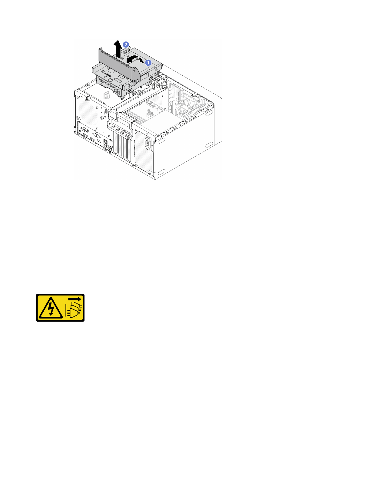
Figure 61. Removing the optical drive cage
After you finish
1. If applicable, replace the 3.5-inch drive cage or replace the 3.5-inch drive, see
“Simple-swap drive and
drive cage replacement (bay 3)” on page 62
.
2. If you are instructed to return the component or optional device, follow all packaging instructions, and
use any packaging materials for shipping that are supplied to you.
Install the optical drive cage
Follow this procedure to install the optical drive cage.
S002
CAUTION:
The power-control button on the device and the power switch on the power supply do not turn off the
electrical current supplied to the device. The device also might have more than one power cord. To
remove all electrical current from the device, ensure that all power cords are disconnected from the
power source.
78
ThinkSystem ST50 V2 Maintenance Manual
S006
CAUTION:
When laser products (such as CD-ROMs, DVD drives, fiber optic devices, or transmitters) are
installed, note the following:
• Do not remove the covers. Removing the covers of the laser product could result in exposure to
hazardous laser radiation. There are no serviceable parts inside the device.
• Use of controls or adjustments or performance of procedures other than those specified herein
might result in hazardous radiation exposure.
About this task
Attention:
• Read
“Safety inspection checklist” on page iv and “Installation guidelines” on page 41 to ensure that you
work safely.
Watch the procedure
A video of this procedure is available at YouTube:
https://www.youtube.com/playlist?list=PLYV5R7hVcs-
AU3iY3F7lq3qfqr5caGbIu
.
Procedure
Step 1. Make sure the cage bar is installed in the chassis. To install the cage bar, see
“Install the server
cover” on page 147
.
Step 2. If necessary, install the 3.5-inch drive assembly to the optical drive cage. See
“Simple-swap drive
and drive cage replacement (bay 3)” on page 62
.
Step 3. Install the optical drive cage.
a.
Align the four pins on the sides of the optical drive cage with the four slots on the chassis
and cage bar; then, lower the optical drive cage into the chassis.
b.
Ensure the optical drive cage is seated correctly; then, rotate the optical drive cage handle
toward the front of the chassis to secure the optical drive cage into place.
Chapter 3. Hardware replacement procedures 79

Figure 62. Installing the optical drive cage
Step 4. If applicable, connect the signal and power cable of the 3.5-inch drive to the system board, see
“Internal cable routing” on page 19.
Procedure
1. To install an optical drive, see
“Install an optical drive” on page 73.
2. Proceed to complete the parts replacement, see
“Complete the parts replacement” on page 158.
Fan replacement
Follow this procedure to remove and install the front fan or rear fan.
Note: For heat sink and fan module replacement, see
“Heat sink and fan module replacement” on page 93.
Remove the fan (front and rear)
Follow this procedure to remove the front fan or rear fan.
S002
CAUTION:
The power-control button on the device and the power switch on the power supply do not turn off the
electrical current supplied to the device. The device also might have more than one power cord. To
remove all electrical current from the device, ensure that all power cords are disconnected from the
power source.
80
ThinkSystem ST50 V2 Maintenance Manual

About this task
Attention:
• Read
“Safety inspection checklist” on page iv and “Installation guidelines” on page 41 to ensure that you
work safely.
• Turn off the server and peripheral devices, and disconnect the power cords and all external cables, see
“Power off the server” on page 9.
• If the server is in a rack, remove it from the rack. See
“Remove the server from the rails” on page 138.
• Remove any locking device that secures the server, such as a Kensington lock or a padlock.
• Place the server on its side with the cover up.
Watch the procedure
A video of this procedure is available at YouTube:
https://www.youtube.com/playlist?list=PLYV5R7hVcs-
AU3iY3F7lq3qfqr5caGbIu
.
Procedure
Step 1. Make preparation for this task.
a. Remove the server cover, see
“Remove the server cover” on page 144.
Note: The heat sink and processor could be very hot. To avoid burning yourself, wait for a few
minutes after turning off the server before you remove the server cover.
b. (Removing the front fan only) Remove the front bezel, see
“Remove the front bezel” on page
84
.
Step 2. Disconnect the fan cable from the system board.
Chapter 3. Hardware replacement procedures 81
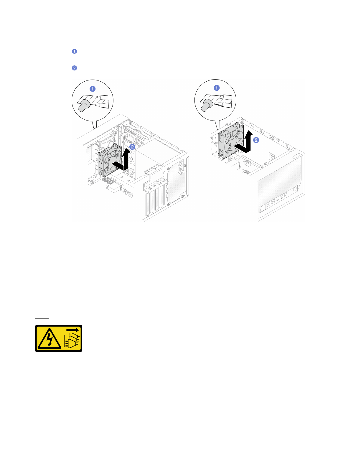
Step 3. Remove the front fan or rear fan from the chassis.
a.
From the outside of the chassis, cut off the four rubber mounts that secure the fan to the
chassis.
b.
Slide the fan away from the chassis; then, lift it out of the chassis.
Figure 63. Removing the front fan or rear fan
After you finish
1. Install a new front fan or rear fan, see “Install the fan (front and rear)” on page 82.
2. If you are instructed to return the component or optional device, follow all packaging instructions, and
use any packaging materials for shipping that are supplied to you.
Install the fan (front and rear)
Follow this procedure to install the front fan or rear fan.
S002
CAUTION:
The power-control button on the device and the power switch on the power supply do not turn off the
electrical current supplied to the device. The device also might have more than one power cord. To
remove all electrical current from the device, ensure that all power cords are disconnected from the
power source.
About this task
Attention:
82
ThinkSystem ST50 V2 Maintenance Manual
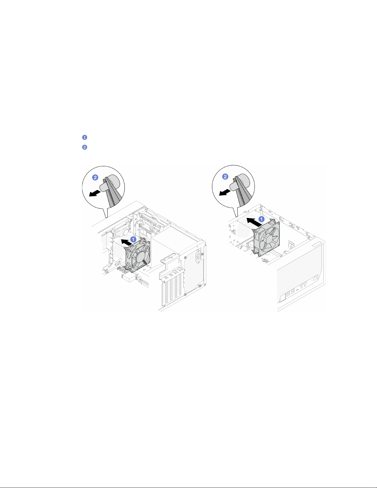
1. Read “Safety inspection checklist” on page iv and “Installation guidelines” on page 41 to ensure that you
work safely.
2. Touch the static-protective package that contains the component to any unpainted metal surface on the
server; then, remove it from the package and place it on a static-protective surface.
Watch the procedure
A video of this procedure is available at YouTube:
https://www.youtube.com/playlist?list=PLYV5R7hVcs-
AU3iY3F7lq3qfqr5caGbIu
.
Procedure
Step 1. Install the front fan or rear fan.
a.
Align the four rubber mounts on the fan with the corresponding holes on the chassis.
b.
With a pair of pliers, gently pull the tips of the four rubber mounts though the holes until the
fan is secured to the chassis.
Figure 64. Installing the front fan or the rear fan
Note: Make sure the rubber mounts are fully pulled out of the holes to secure the fans steadily
to the chassis.
Chapter 3. Hardware replacement procedures 83
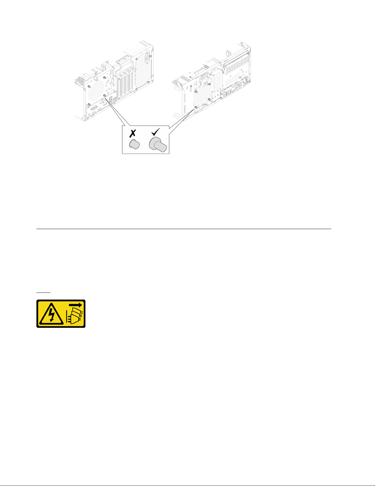
Figure 65. Front fan and rear fan rubber mounts installation
Step 2. Connect the fan cable to the system board, see
“Internal cable routing” on page 19.
After you finish
1. (Removing the front fan only) Reinstall the front bezel, see
“Install the front bezel” on page 86.
2. Proceed to complete the parts replacement, see
“Complete the parts replacement” on page 158.
Front bezel replacement
Follow this procedure to remove and install the front bezel.
Remove the front bezel
Follow this procedure to remove the front bezel.
S002
CAUTION:
The power-control button on the device and the power switch on the power supply do not turn off the
electrical current supplied to the device. The device also might have more than one power cord. To
remove all electrical current from the device, ensure that all power cords are disconnected from the
power source.
About this task
Attention:
• Read
“Safety inspection checklist” on page iv and “Installation guidelines” on page 41 to ensure that you
work safely.
• Turn off the server and peripheral devices, and disconnect the power cords and all external cables, see
“Power off the server” on page 9.
84
ThinkSystem ST50 V2 Maintenance Manual

• If the server is in a rack, remove it from the rack. See “Remove the server from the rails” on page 138.
• Remove any locking device that secures the server, such as a Kensington lock or a padlock.
• Place the server on its side with the cover up.
Watch the procedure
A video of this procedure is available at YouTube:
https://www.youtube.com/playlist?list=PLYV5R7hVcs-
AU3iY3F7lq3qfqr5caGbIu
.
Chapter 3. Hardware replacement procedures 85
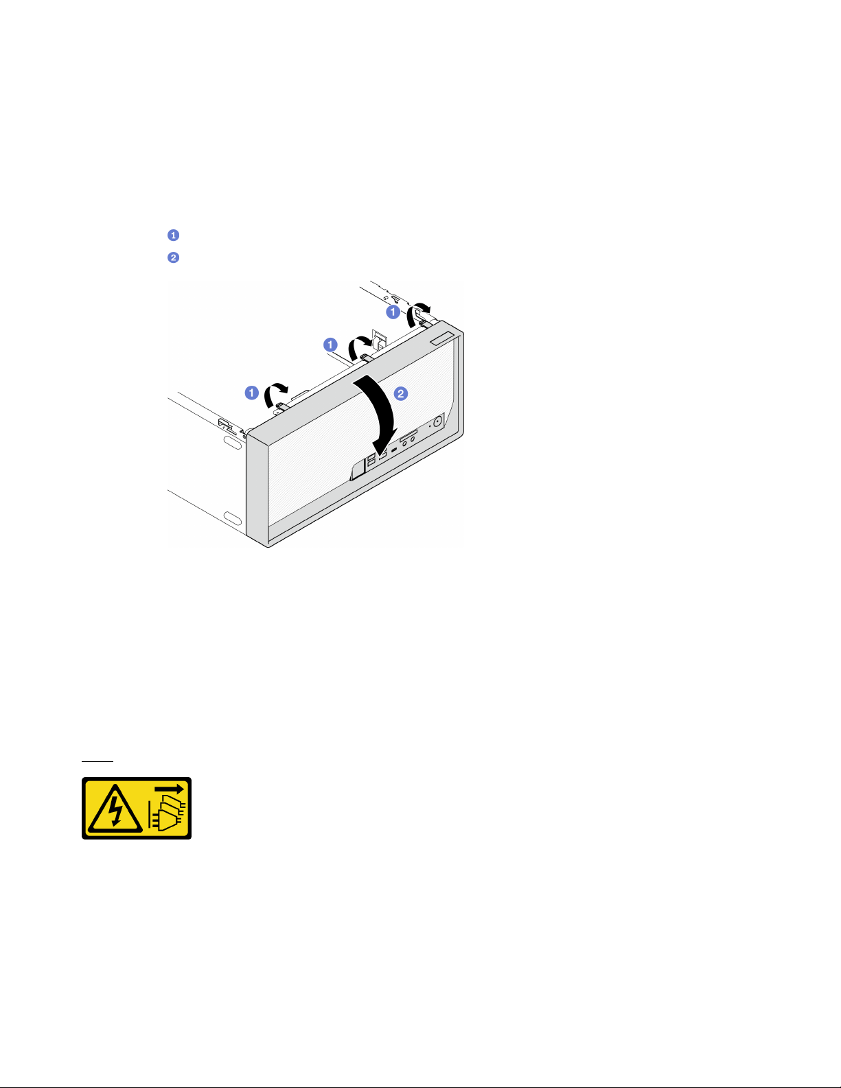
Procedure
Step 1. Make preparation for this task.
a. Remove the server cover, see
“Remove the server cover” on page 144.
Note: The heat sink and processor could be very hot. To avoid burning yourself, wait for a few
minutes after turning off the server before you remove the server cover.
Step 2. Remove the front bezel.
a.
Release the three plastic tabs on the front bezel.
b.
Rotate the front bezel to remove it from the chassis.
Figure 66. Removing the front bezel
After you finish
If you are instructed to return the component or optional device, follow all packaging instructions, and use
any packaging materials for shipping that are supplied to you.
Install the front bezel
Follow this procedure to install the front bezel.
S002
CAUTION:
The power-control button on the device and the power switch on the power supply do not turn off the
electrical current supplied to the device. The device also might have more than one power cord. To
remove all electrical current from the device, ensure that all power cords are disconnected from the
power source.
About this task
86 ThinkSystem ST50 V2 Maintenance Manual
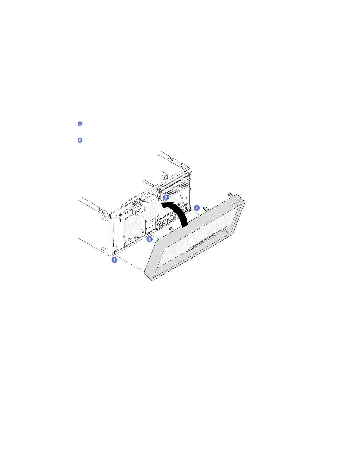
Attention:
• Read
“Safety inspection checklist” on page iv and “Installation guidelines” on page 41 to ensure that you
work safely.
Watch the procedure
A video of this procedure is available at YouTube:
https://www.youtube.com/playlist?list=PLYV5R7hVcs-
AU3iY3F7lq3qfqr5caGbIu
.
Procedure
Step 1. Install the front bezel.
a.
Insert the three plastic tabs on the bottom of the front bezel with the corresponding slots on
the front of the chassis.
b.
Pivot the front bezel towards to chassis until it snaps into place.
Figure 67. Installing the front bezel
After you finish
Proceed to complete the parts replacement, see
“Complete the parts replacement” on page 158.
Front panel replacement
Follow this procedure to remove and install the front panel.
Remove the front panel
Follow this procedure to remove the front panel.
Chapter 3. Hardware replacement procedures 87

S002
CAUTION:
The power-control button on the device and the power switch on the power supply do not turn off the
electrical current supplied to the device. The device also might have more than one power cord. To
remove all electrical current from the device, ensure that all power cords are disconnected from the
power source.
About this task
Attention:
• Read
“Safety inspection checklist” on page iv and “Installation guidelines” on page 41 to ensure that you
work safely.
• Turn off the server and peripheral devices, and disconnect the power cords and all external cables, see
“Power off the server” on page 9.
• If the server is in a rack, remove it from the rack. See
“Remove the server from the rails” on page 138.
• Remove any locking device that secures the server, such as a Kensington lock or a padlock.
• Place the server on its side with the cover up.
Watch the procedure
A video of this procedure is available at YouTube:
https://www.youtube.com/playlist?list=PLYV5R7hVcs-
AU3iY3F7lq3qfqr5caGbIu
.
Procedure
Step 1. Make preparation for this task.
a. Remove the server cover, see
“Remove the server cover” on page 144.
Note: The heat sink and processor could be very hot. To avoid burning yourself, wait for a few
minutes after turning off the server before you remove the server cover.
b. Remove the front bezel. See
“Remove the front bezel” on page 84.
Step 2. Disconnect the power button cable from the system board.
88
ThinkSystem ST50 V2 Maintenance Manual
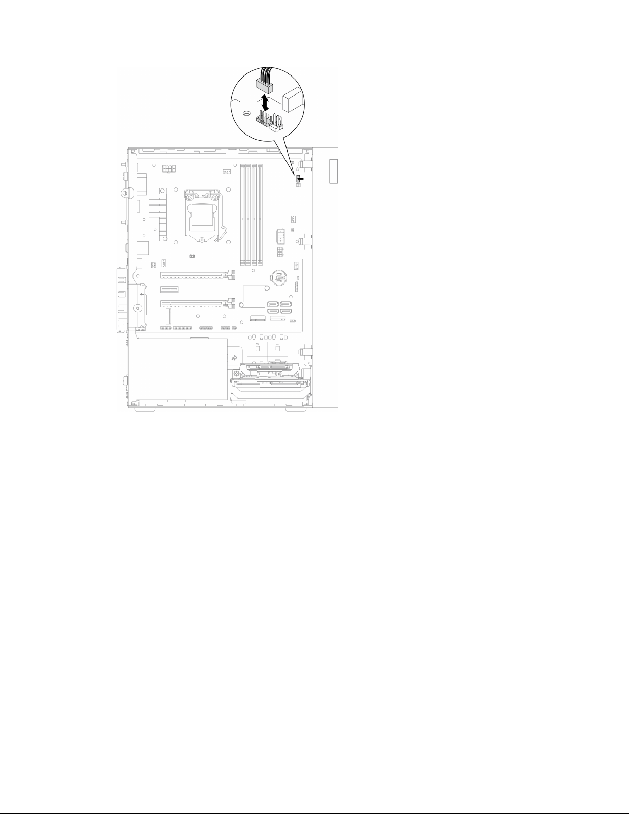

Figure 69. Removing the screw the secures the front bezel to the chassis
Step 4. Remove the front panel.
a.
Rotate the left end of the front panel away from the chassis.
b.
Remove the front panel from the chassis.
90
ThinkSystem ST50 V2 Maintenance Manual
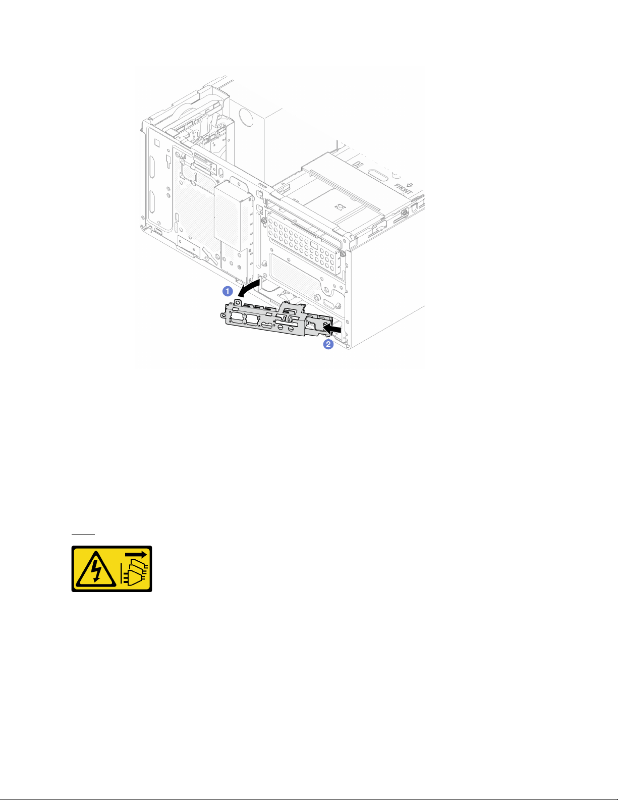
Figure 70. Removing front panel from the chassis
Procedure
1. Install a new front panel, see “Install the front panel” on page 91.
2. If you are instructed to return the component or optional device, follow all packaging instructions, and
use any packaging materials for shipping that are supplied to you.
Install the front panel
Follow this procedure to install the front panel.
S002
CAUTION:
The power-control button on the device and the power switch on the power supply do not turn off the
electrical current supplied to the device. The device also might have more than one power cord. To
remove all electrical current from the device, ensure that all power cords are disconnected from the
power source.
About this task
Attention:
Chapter 3. Hardware replacement procedures 91
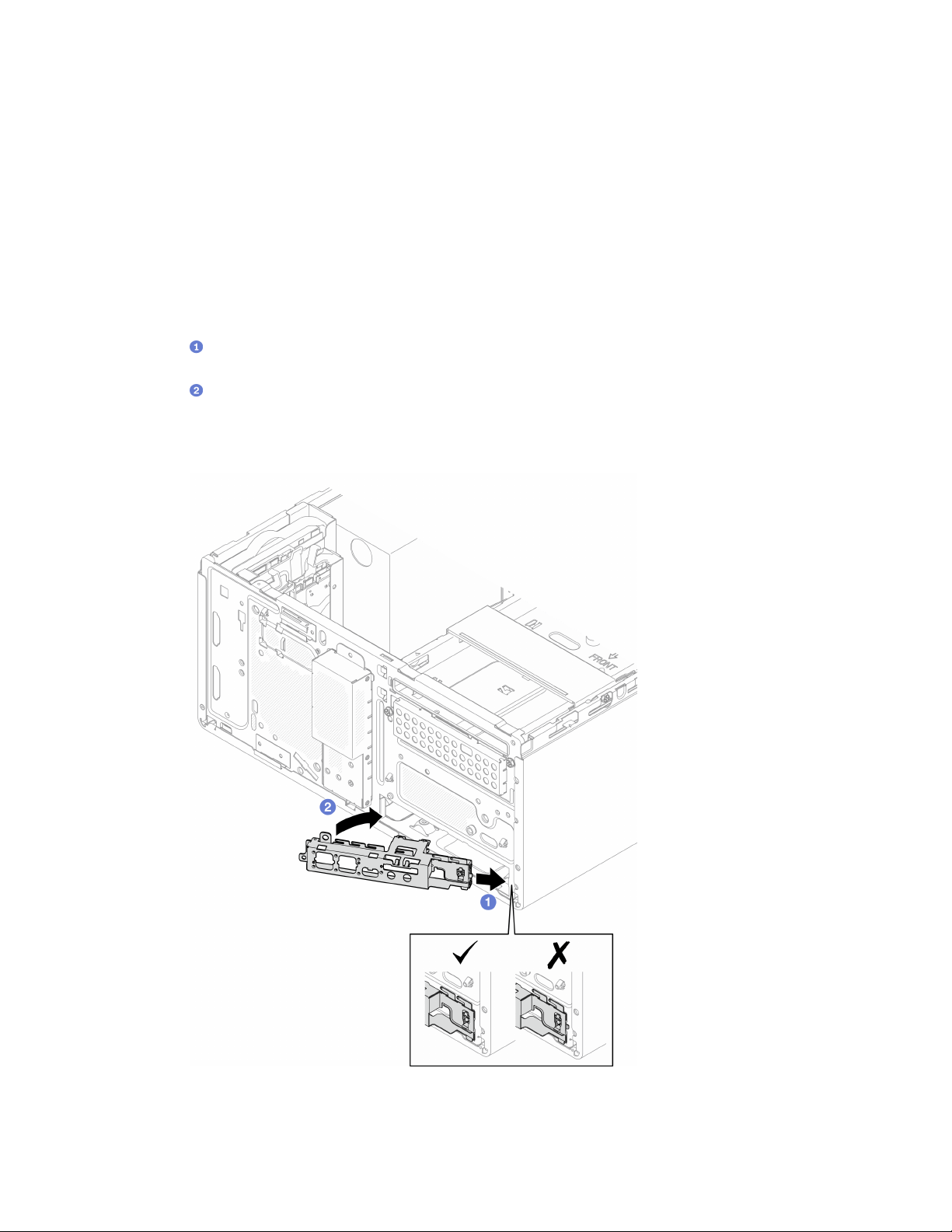
1. Read “Safety inspection checklist” on page iv and “Installation guidelines” on page 41 to ensure that you
work safely.
2. Touch the static-protective package that contains the component to any unpainted metal surface on the
server; then, remove it from the package and place it on a static-protective surface.
Watch the procedure
A video of this procedure is available at YouTube:
https://www.youtube.com/playlist?list=PLYV5R7hVcs-
AU3iY3F7lq3qfqr5caGbIu
.
Procedure
Step 1. Install the front panel.
a.
There is a small tab on the right side of the front panel. Place the tab behind the front panel
slot on the chassis.
b.
Align the guide hole and screw hole on the front panel with the guide pin and screw slot on
the chassis; then, install the front panel to the chassis.
Note: Make sure the small tab on the right side of the front panel is placed behind the chassis.
Figure 71. Installing front panel to chassis
92 ThinkSystem ST50 V2 Maintenance Manual
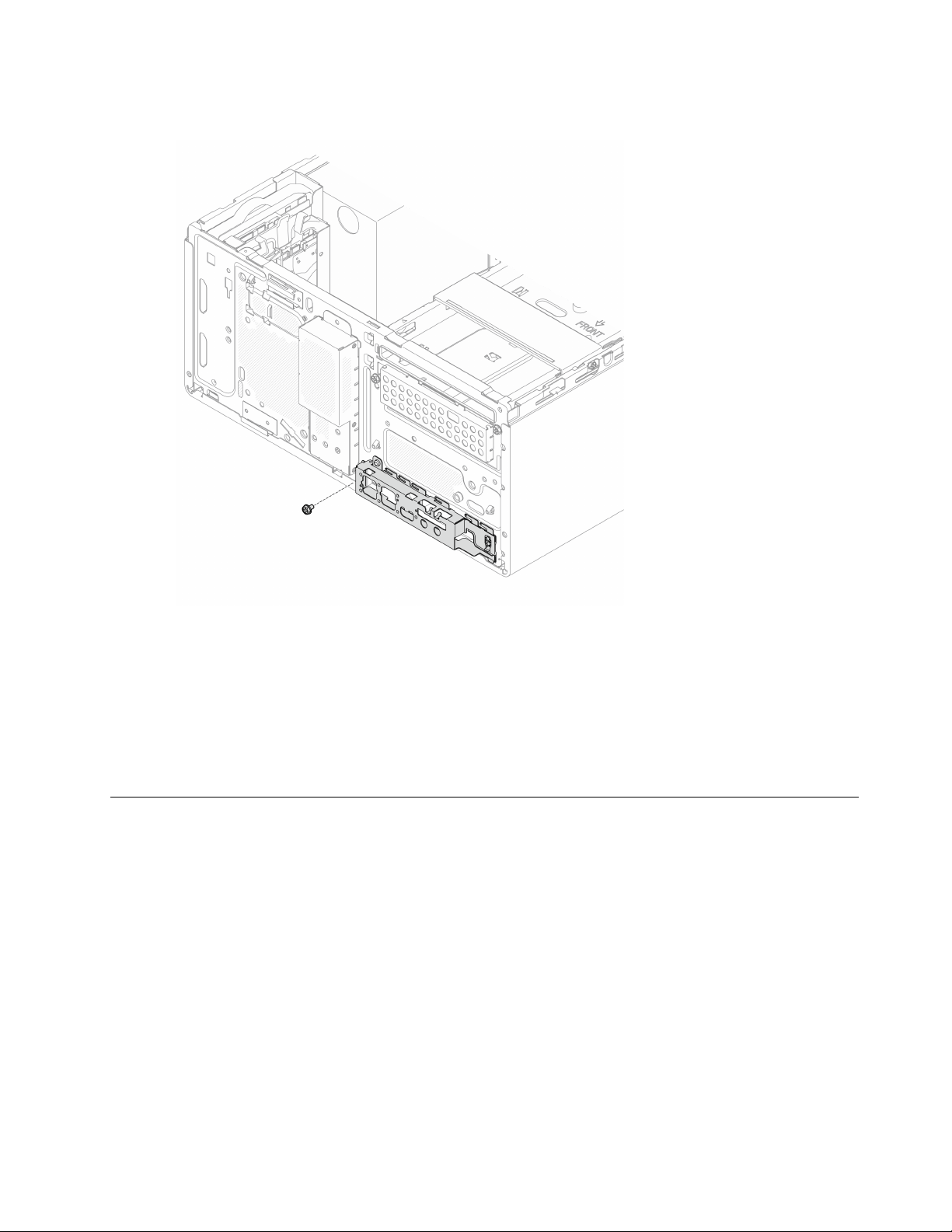
Step 2. Fasten the screw to secure the front panel to the chassis.
Figure 72. Securing front panel to the chassis
Step 3. Connect the power button cable to the system board, see “Internal cable routing” on page 19.
Procedure
1. Reinstall the front bezel, see
“Install the front bezel” on page 86.
2. Proceed to complete the parts replacement, see
“Complete the parts replacement” on page 158.
Heat sink and fan module replacement
Follow this procedure to remove and install the heat sink and fan module.
Remove the heat sink and fan module (trained technician only)
Follow this procedure to remove the heat sink and fan module. This procedure must be executed by a trained
technician.
Chapter 3. Hardware replacement procedures 93

S002
CAUTION:
The power-control button on the device and the power switch on the power supply do not turn off the
electrical current supplied to the device. The device also might have more than one power cord. To
remove all electrical current from the device, ensure that all power cords are disconnected from the
power source.
About this task
Attention:
• Read
“Safety inspection checklist” on page iv and “Installation guidelines” on page 41 to ensure that you
work safely.
• Turn off the server and peripheral devices, and disconnect the power cords and all external cables, see
“Power off the server” on page 9.
• If the server is in a rack, remove it from the rack. See
“Remove the server from the rails” on page 138.
• Remove any locking device that secures the server, such as a Kensington lock or a padlock.
• Place the server on its side with the cover up.
Watch the procedure
A video of this procedure is available at YouTube:
https://www.youtube.com/playlist?list=PLYV5R7hVcs-
AU3iY3F7lq3qfqr5caGbIu
.
Procedure
Step 1. Make preparation for your task.
a. Remove the server cover, see
“Remove the server cover” on page 144.
Note: The heat sink and processor could be very hot. To avoid burning yourself, wait for a few
minutes after turning off the server before you remove the server cover.
b. If necessary, remove the optical drive cage, see
“Remove the optical drive cage” on page 76.
Step 2. Disconnect the heat sink and fan module cables from the system board.
Step 3. If the server is installed with processor with 95W TDP, the heat sink fan is installed on the rear side
of the chassis. Remove the four securing screws from outside of the chassis.
94
ThinkSystem ST50 V2 Maintenance Manual
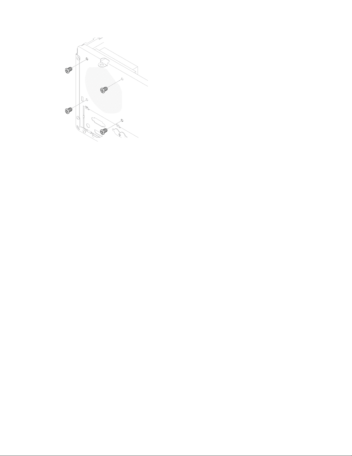
Figure 73. Removing the four screws securing the heat sink fan to the chassis
Step 4. Loosen screw 1 and 2 first; then loosen screw 3 and 4.
a. Partially loosen screw 1.
b. Fully loosen screw 2.
c. Fully loosen screw 1.
d. Partially loosen screw 3.
e. Fully loosen screw 4.
f. Fully loosen screw 3.
Notes:
1. Gently remove the four screws to avoid any possible damage to the system board.
2. Always keep the four screws attached to the heat sink and fan module.
3. Do not touch the thermal grease while handling the heat sink and fan module.
Loosening the screws on the heat sink and fan module for processor with TDP lower than
95W
Chapter 3. Hardware replacement procedures 95
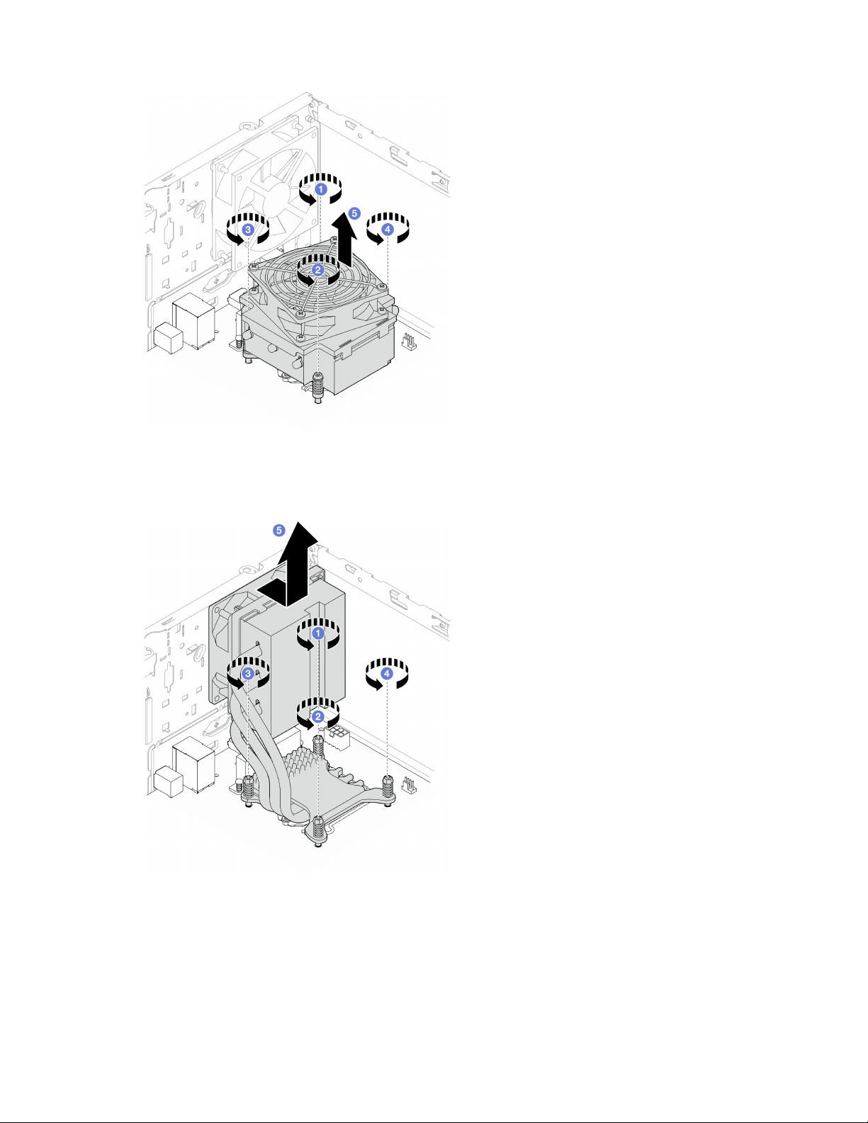
Figure 74. Loosening the screws on the heat sink and fan module for processor with TDP lower than 95W
Loosening the screws on the heat sink and fan module for processor with 95W TDP
Figure 75. Loosening the screws on the heat sink and fan module for processor with 95W TDP
Step 5. Evenly lift the heat sink and fan module, and remove it from the system board.
After you finish
1. If applicable, install a new heat sink and fan module, see
“Install the heat sink and the fan module
(trained technician only)” on page 97.
96 ThinkSystem ST50 V2 Maintenance Manual
2. If you are instructed to return the component or optional device, follow all packaging instructions, and
use any packaging materials for shipping that are supplied to you.
Install the heat sink and the fan module (trained technician only)
Follow this procedure to install the heat sink and the fan module. This procedure must be executed by a
trained technician.
S002
CAUTION:
The power-control button on the device and the power switch on the power supply do not turn off the
electrical current supplied to the device. The device also might have more than one power cord. To
remove all electrical current from the device, ensure that all power cords are disconnected from the
power source.
About this task
Attention:
1. Read
“Safety inspection checklist” on page iv and “Installation guidelines” on page 41 to ensure that you
work safely.
2. Touch the static-protective package that contains the component to any unpainted metal surface on the
server; then, remove it from the package and place it on a static-protective surface.
Watch the procedure
A video of this procedure is available at YouTube:
https://www.youtube.com/playlist?list=PLYV5R7hVcs-
AU3iY3F7lq3qfqr5caGbIu
.
Procedure
Step 1. Install the processor if one is not yet installed. See
“Install the processor (trained technician only)”
on page 136
.
Step 2. Align the four screws on the heat sink and fan assembly with the corresponding screw holes on the
system board. Make sure the fan cable is close to the heat sink fan connector, see
“System board
components” on page 18
.
Chapter 3. Hardware replacement procedures 97
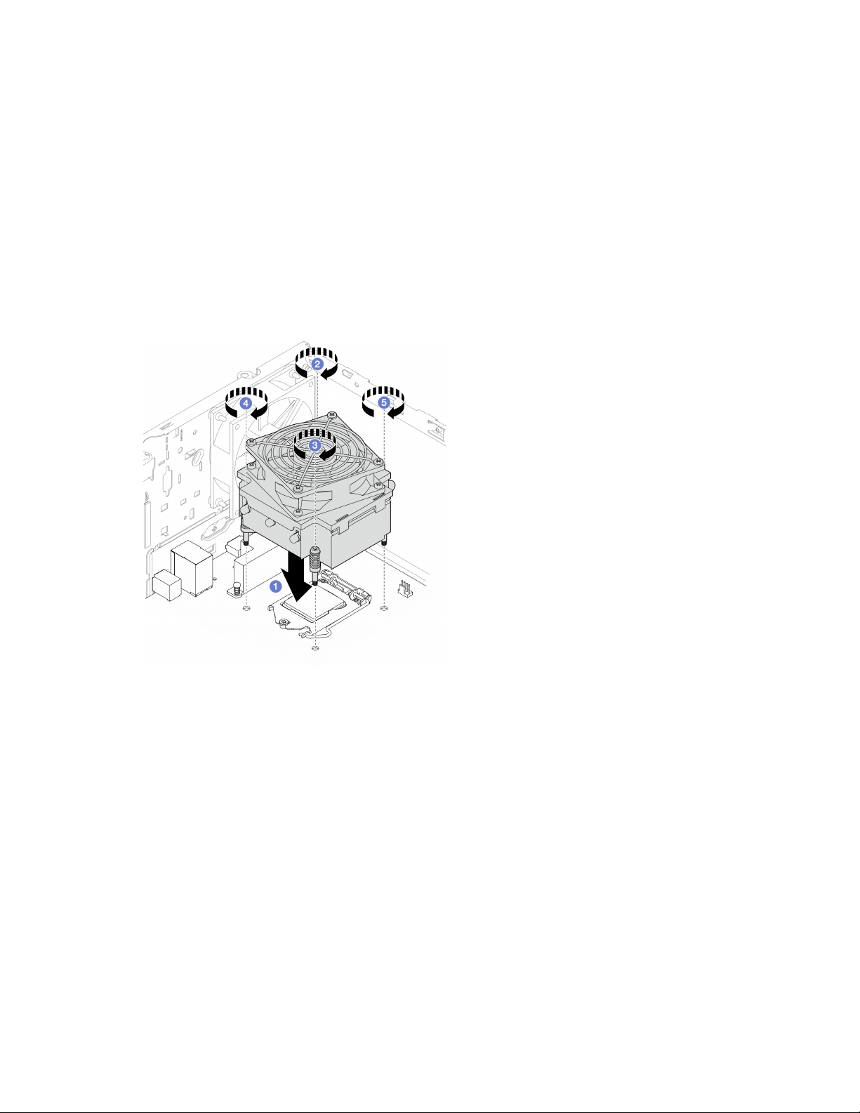
Step 3. Tighten screw 1 and 2 first, then tighten screw 3 and 4.
a. Partially tighten screw 1.
b. Fully tighten screw 2.
c. Fully tighten screw 1.
d. Partially tighten screw 3.
e. Fully tighten screw 4.
f. Fully tighten screw 3.
Note: Do not touch the thermal grease while handling the heat sink and fan module.
Tightening the screws on the heat sink and fan module for processor with TDP lower than
95W
Figure 76. Tightening the screws on the heat sink and fan module for processor with TDP lower than 95W
Tightening the screws on the heat sink and fan module for processor with 95W TDP
98
ThinkSystem ST50 V2 Maintenance Manual
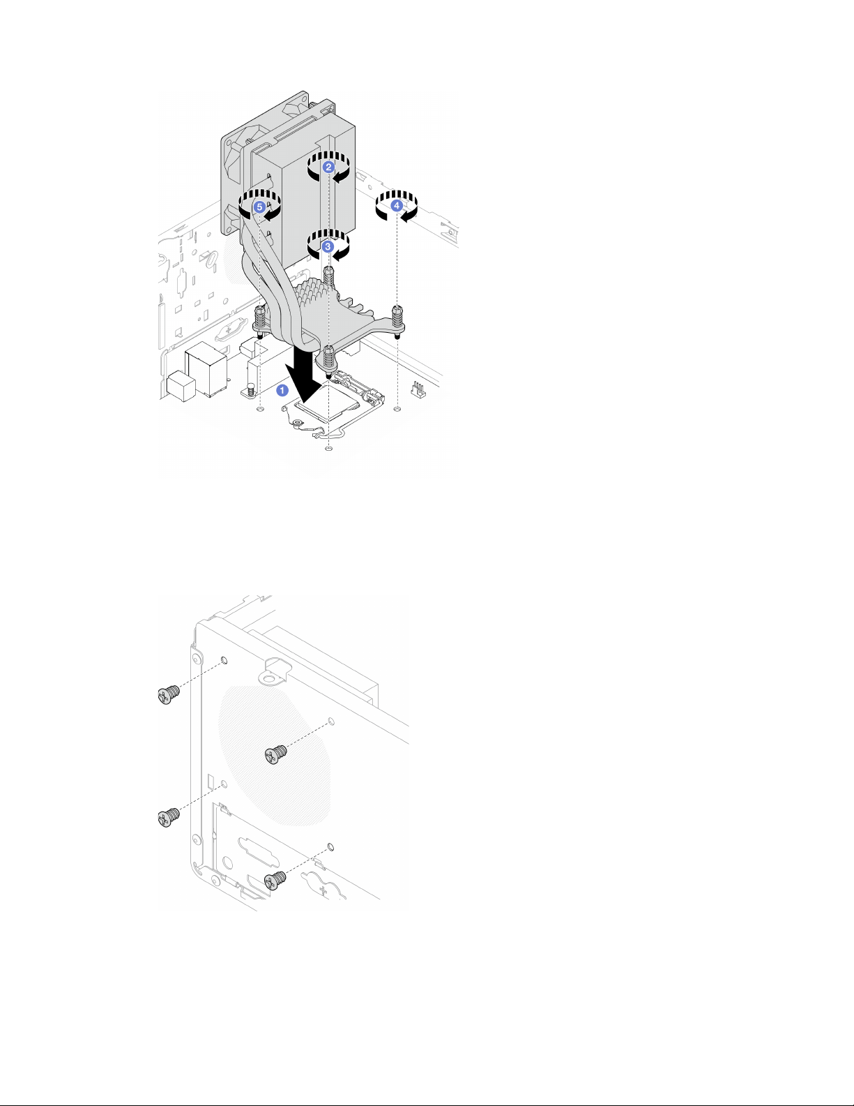
Figure 77. Tightening the screws on the heat sink and fan module for processor with 95W TDP
Step 4. If the server is installed with processor with 95W TDP, the heat sink fan should be installed on the
rear side of the chassis. Align the four fan screws to the screw holes on the rear side of the chassis,
and fasten the screws to secure it.
Figure 78. Installing the heat sink fan to the rear of the chassis
Step 5. Connect the heat sink fan cable to the system board, see
“Internal cable routing” on page 19.
Chapter 3. Hardware replacement procedures 99
After you finish
1. If necessary, reinstall the optical drive cage, see
“Install the optical drive cage” on page 78.
2. Proceed to complete the parts replacement, see “Complete the parts replacement” on page 158.
Intrusion switch replacement
The intrusion switch generates an event in the system event log (SEL) when the server cover is not properly
installed. Follow this procedure to remove and install the intrusion switch.
Remove the intrusion switch
Follow this procedure to remove the intrusion switch.
S002
CAUTION:
The power-control button on the device and the power switch on the power supply do not turn off the
electrical current supplied to the device. The device also might have more than one power cord. To
remove all electrical current from the device, ensure that all power cords are disconnected from the
power source.
About this task
Attention:
• Read
“Safety inspection checklist” on page iv and “Installation guidelines” on page 41 to ensure that you
work safely.
• Turn off the server and peripheral devices, and disconnect the power cords and all external cables, see
“Power off the server” on page 9.
• If the server is in a rack, remove it from the rack. See
“Remove the server from the rails” on page 138.
• Remove any locking device that secures the server, such as a Kensington lock or a padlock.
• Place the server on its side with the cover up.
Watch the procedure
A video of this procedure is available at YouTube:
https://www.youtube.com/playlist?list=PLYV5R7hVcs-
AU3iY3F7lq3qfqr5caGbIu
.
Procedure
Step 1. Make preparation for this task.
a. Remove the server cover, see
“Remove the server cover” on page 144.
Note: The heat sink and processor could be very hot. To avoid burning yourself, wait for a few
minutes after turning off the server before you remove the server cover.
Step 2. Disconnect the intrusion switch cable from the system board.
100
ThinkSystem ST50 V2 Maintenance Manual
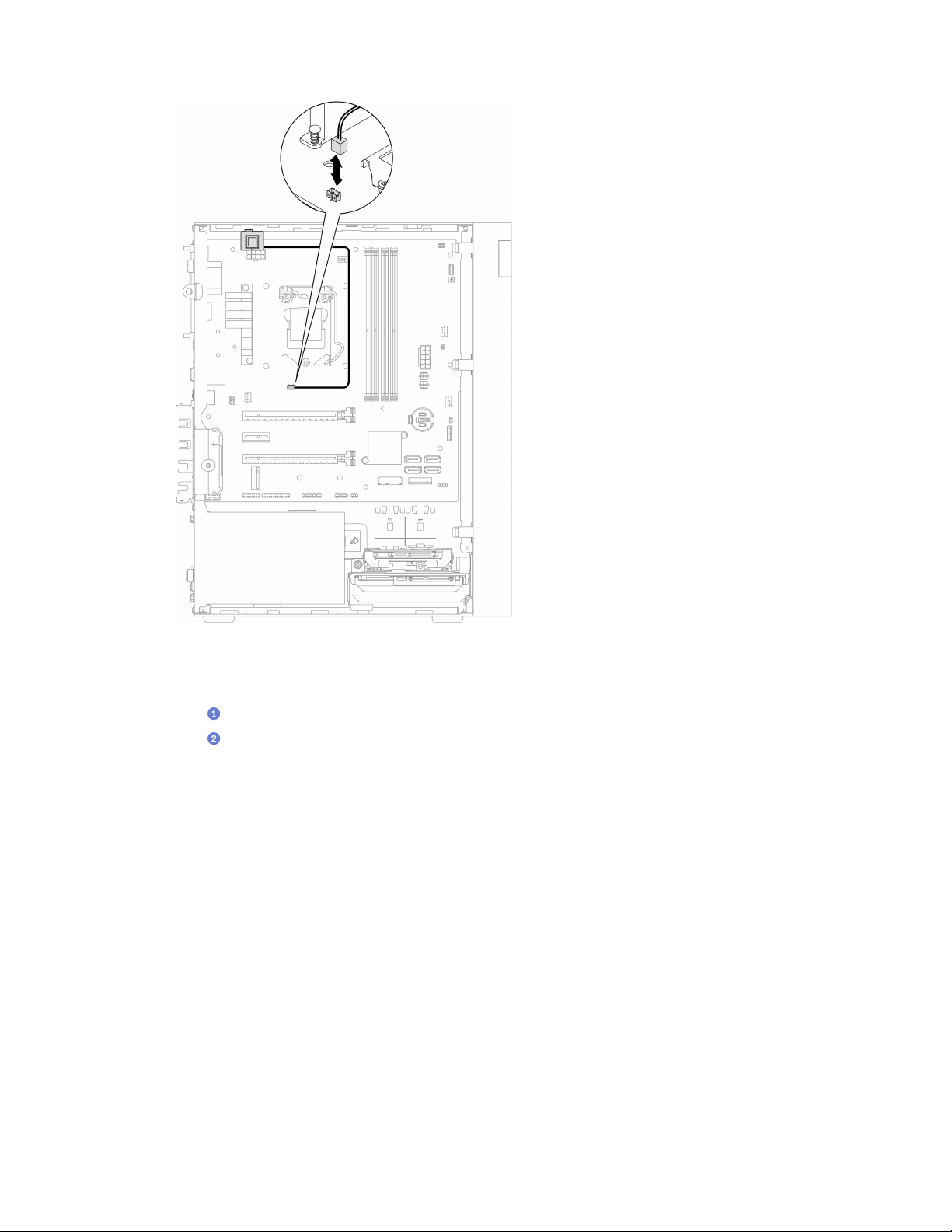
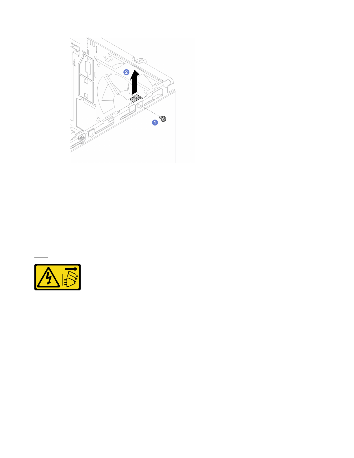
Figure 80. Removing the intrusion switch
After you finish
1. Install a new intrusion switch, see
“Install the intrusion switch” on page 102.
2. If you are instructed to return the component or optional device, follow all packaging instructions, and
use any packaging materials for shipping that are supplied to you.
Install the intrusion switch
Follow this procedure to install the intrusion switch.
S002
CAUTION:
The power-control button on the device and the power switch on the power supply do not turn off the
electrical current supplied to the device. The device also might have more than one power cord. To
remove all electrical current from the device, ensure that all power cords are disconnected from the
power source.
About this task
Attention:
1. Read
“Safety inspection checklist” on page iv and “Installation guidelines” on page 41 to ensure that you
work safely.
2. Touch the static-protective package that contains the component to any unpainted metal surface on the
server; then, remove it from the package and place it on a static-protective surface.
Watch the procedure
102
ThinkSystem ST50 V2 Maintenance Manual
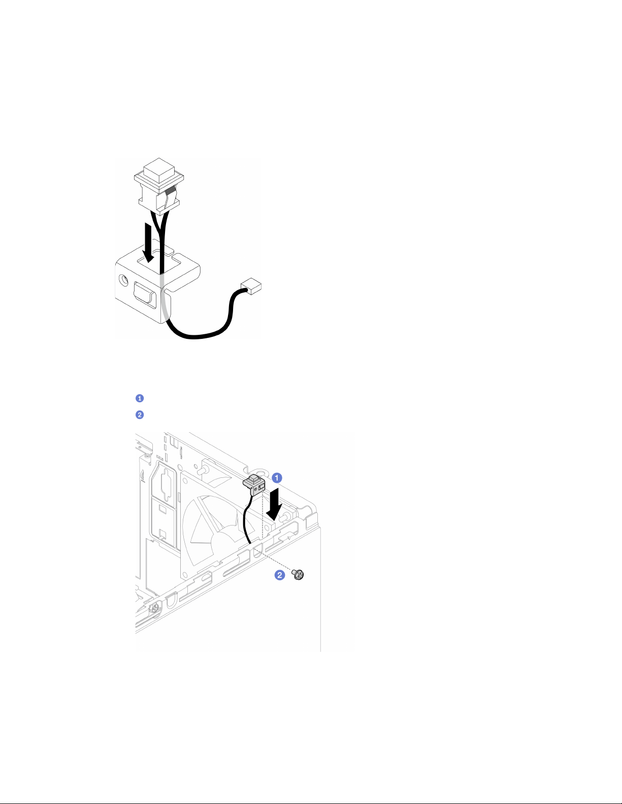
A video of this procedure is available at YouTube: https://www.youtube.com/playlist?list=PLYV5R7hVcs-
AU3iY3F7lq3qfqr5caGbIu
.
Procedure
Step 1. (Optional) If you are installing an intrusion switch option, assemble the intrusion switch. Insert the
intrusion switch into the bracket until it click into place.
Figure 81. Assembling the intrusion switch
Step 2. Install the intrusion switch.
a.
Align the intrusion switch to the slot on the chassis.
b.
Fasten the screw to secure the intrusion switch to the chassis.
Figure 82. Installing the intrusion switch
Step 3. Connect the intrusion switch cable to the system board, see “Internal cable routing” on page 19.
After you finish
Chapter 3. Hardware replacement procedures 103

Proceed to complete the parts replacement, see “Complete the parts replacement” on page 158.
M.2 drive and retainer replacement
Follow this procedure to remove and install the M.2 drive and the M.2 drive retainer.
Remove an M.2 drive
Follow this procedure to remove an M.2 drive.
S002
CAUTION:
The power-control button on the device and the power switch on the power supply do not turn off the
electrical current supplied to the device. The device also might have more than one power cord. To
remove all electrical current from the device, ensure that all power cords are disconnected from the
power source.
About this task
Attention:
• Read
“Safety inspection checklist” on page iv and “Installation guidelines” on page 41 to ensure that you
work safely.
• Turn off the server and peripheral devices, and disconnect the power cords and all external cables, see
“Power off the server” on page 9.
• If the server is in a rack, remove it from the rack. See
“Remove the server from the rails” on page 138.
• Remove any locking device that secures the server, such as a Kensington lock or a padlock.
• Place the server on its side with the cover up.
Watch the procedure
A video of this procedure is available at YouTube:
https://www.youtube.com/playlist?list=PLYV5R7hVcs-
AU3iY3F7lq3qfqr5caGbIu
.
Procedure
Step 1. Make preparation for this task.
a. Remove the server cover, see
“Remove the server cover” on page 144.
Note: The heat sink and processor could be very hot. To avoid burning yourself, wait for a few
minutes after turning off the server before you remove the server cover.
b. If applicable, remove the 2.5-inch drive from bay 2, see
“Remove a simple-swap drive (bay 1-
2)” on page 50
.
Step 2. Locate the M.2 drive.
104
ThinkSystem ST50 V2 Maintenance Manual
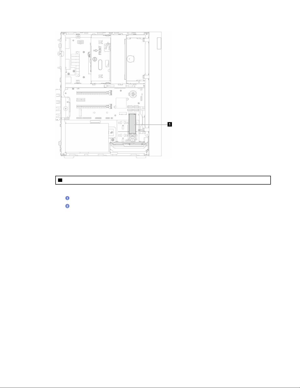
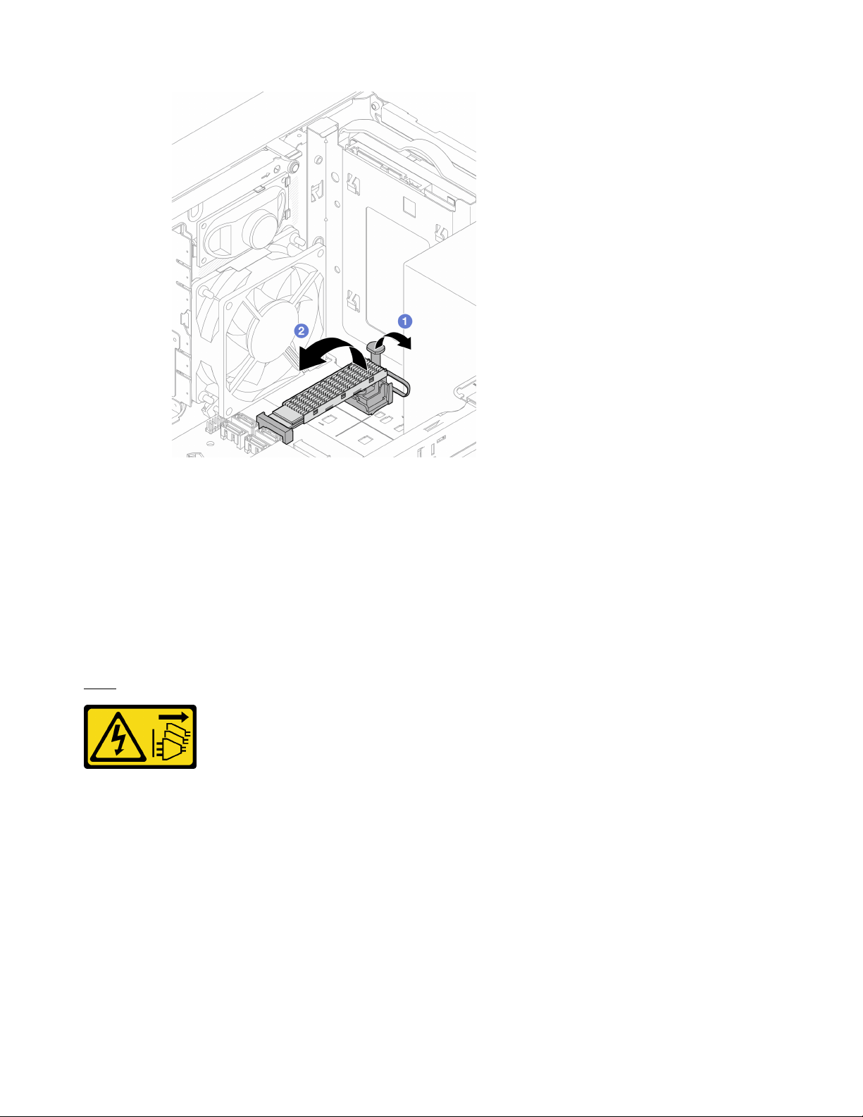
Figure 84. Removing the M.2 drive
After you finish
1. Install a new M.2 drive if necessary, see
“Install an M.2 drive” on page 106.
2. If you are instructed to return the component or optional device, follow all packaging instructions, and
use any packaging materials for shipping that are supplied to you.
Install an M.2 drive
Follow this procedure to install an M.2 drive.
S002
CAUTION:
The power-control button on the device and the power switch on the power supply do not turn off the
electrical current supplied to the device. The device also might have more than one power cord. To
remove all electrical current from the device, ensure that all power cords are disconnected from the
power source.
About this task
Attention:
• Read
“Safety inspection checklist” on page iv and “Installation guidelines” on page 41 to ensure that you
work safely.
• Touch the static-protective package that contains the component to any unpainted metal surface on the
server; then, remove it from the package and place it on a static-protective surface.
106
ThinkSystem ST50 V2 Maintenance Manual
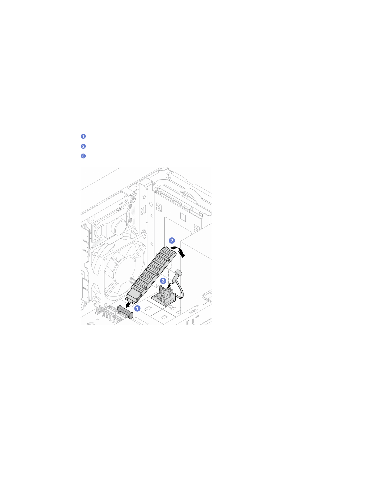
Watch the procedure
A video of this procedure is available at YouTube:
https://www.youtube.com/playlist?list=PLYV5R7hVcs-
AU3iY3F7lq3qfqr5caGbIu
.
About this task
Step 1. Make sure the 2.5-drive is removed from drive bay 2, see “Remove a simple-swap drive (bay 1-2)”
on page 50
.
Step 2. Make sure the post on the M.2 drive retainer is lifted away from the retainer.
Step 3. Install the M.2 drive.
Note: The thermal sensor cable should be placed under the M.2 drive.
a.
Position the M.2 drive at an angle and insert it to the M.2 connector.
b.
Place down the M.2 drive onto the M.2 drive retainer.
c.
Insert the retainer post into the retainer to secure the M.2 drive in place.
Figure 85. Installing the M.2 drive
After you finish
1. If necessary, reinstall the 2.5-inch drive to the drive bay 2, see
“Install a simple-swap drive (bay 1-2)” on
page 53
.
2. Proceed to complete the parts replacement, see “Complete the parts replacement” on page 158.
Remove the M.2 drive retainer
Follow this procedure to remove the M.2 drive retainer.
Chapter 3. Hardware replacement procedures 107
S002
CAUTION:
The power-control button on the device and the power switch on the power supply do not turn off the
electrical current supplied to the device. The device also might have more than one power cord. To
remove all electrical current from the device, ensure that all power cords are disconnected from the
power source.
About this task
Attention:
• Read
“Safety inspection checklist” on page iv and “Installation guidelines” on page 41 to ensure that you
work safely.
• Turn off the server and peripheral devices, and disconnect the power cords and all external cables, see
“Power off the server” on page 9.
• If the server is in a rack, remove it from the rack. See
“Remove the server from the rails” on page 138.
• Remove any locking device that secures the server, such as a Kensington lock or a padlock.
• Place the server on its side with the cover up.
Watch the procedure
A video of this procedure is available at YouTube:
https://www.youtube.com/playlist?list=PLYV5R7hVcs-
AU3iY3F7lq3qfqr5caGbIu
.
Procedure
Step 1. Make preparation for this task.
a. Remove the server cover, see
“Remove the server cover” on page 144.
Note: The heat sink and processor could be very hot. To avoid burning yourself, wait for a few
minutes after turning off the server before you remove the server cover.
b. If a 2.5-inch drive is installed in drive bay 2, remove it from the chassis, see
“Remove a simple-
swap drive (bay 1-2)” on page 50
.
c. Remove the M.2 drive, see
“Remove an M.2 drive” on page 104.
Step 2. Locate the M.2 drive retainer.
108
ThinkSystem ST50 V2 Maintenance Manual
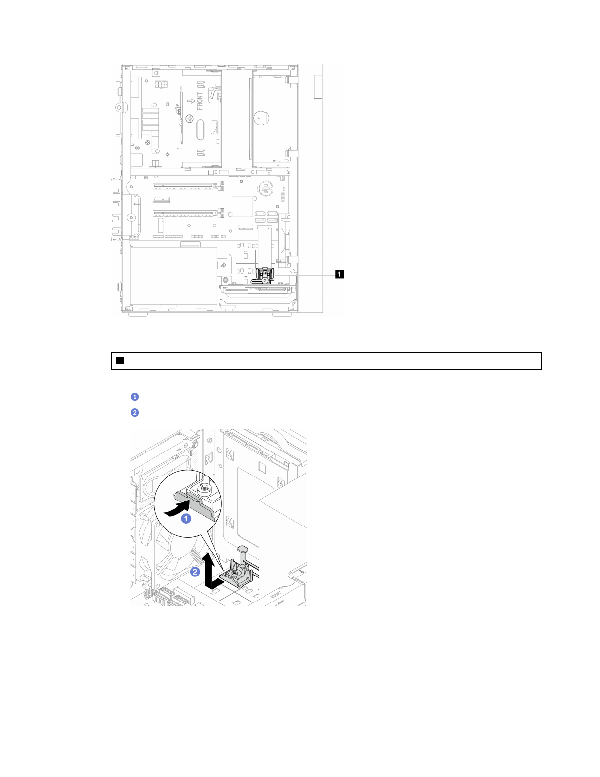
Figure 86. M.2 drive retainer location
1 M.2 drive retainer
Step 3. Remove the M.2 drive retainer.
a.
Press the tab on the retainer and slightly push the nub upward.
b.
Slide the retainer forward and lift it out of the chassis.
Figure 87. Removing the M.2 drive retainer
After you finish
1. Install a new M.2 drive retainer, see
“Install the M.2 drive retainer” on page 110.
2. If you are instructed to return the component or optional device, follow all packaging instructions, and
use any packaging materials for shipping that are supplied to you.
Chapter 3. Hardware replacement procedures 109
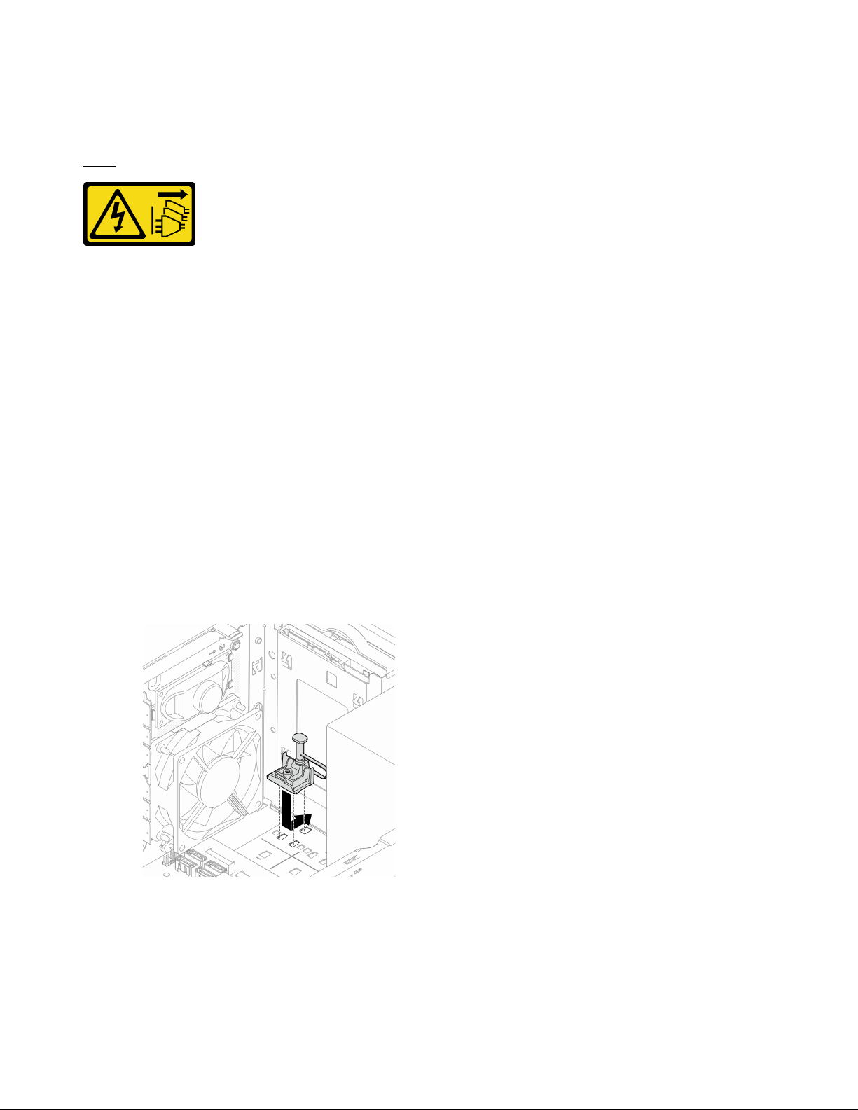
Install the M.2 drive retainer
Follow this procedure to install the M.2 drive retainer.
S002
CAUTION:
The power-control button on the device and the power switch on the power supply do not turn off the
electrical current supplied to the device. The device also might have more than one power cord. To
remove all electrical current from the device, ensure that all power cords are disconnected from the
power source.
About this task
Attention:
• Read
“Safety inspection checklist” on page iv and “Installation guidelines” on page 41 to ensure that you
work safely.
Watch the procedure
A video of this procedure is available at YouTube:
https://www.youtube.com/playlist?list=PLYV5R7hVcs-
AU3iY3F7lq3qfqr5caGbIu
.
After you finish
Step 1. Align the M.2 drive retainer with the three slots on chassis, and lower the retainer into the chassis;
then, slide the retainer toward the 2.5-inch drive to secure it in place.
Figure 88. Installing the M.2 drive retainer
After you finish
1. Install an M.2 drive, see
“Install an M.2 drive” on page 106.
2. If necessary, reinstall the 2.5-inch drive to the drive bay 2, see
“Install a simple-swap drive (bay 1-2)” on
page 53.
110 ThinkSystem ST50 V2 Maintenance Manual

Memory module replacement
Follow this procedure to remove and install a memory module.
Remove a memory module
Follow this procedure to remove a memory module
S002
CAUTION:
The power-control button on the device and the power switch on the power supply do not turn off the
electrical current supplied to the device. The device also might have more than one power cord. To
remove all electrical current from the device, ensure that all power cords are disconnected from the
power source.
About this task
Attention:
• Read
“Safety inspection checklist” on page iv and “Installation guidelines” on page 41 to ensure that you
work safely.
• Turn off the server and peripheral devices, and disconnect the power cords and all external cables, see
“Power off the server” on page 9.
• If the server is in a rack, remove it from the rack. See
“Remove the server from the rails” on page 138.
• Remove any locking device that secures the server, such as a Kensington lock or a padlock.
• Place the server on its side with the cover up.
Memory modules are sensitive to static discharge and require special handling. In addition to the standard
guidelines of
“Handling static-sensitive devices” on page 43:
• Always wear an electrostatic-discharge strap when removing or installing memory modules. Electrostatic-
discharge gloves can also be used.
• Keep each memory module separated from one another. Do not stack memory modules directly on top of
each other during storage.
• Keep the gold memory module connector contacts from touching anything.
• Handle memory modules with care: never bend, twist, or drop a memory module.
Watch the procedure
A video of this procedure is available at YouTube:
https://www.youtube.com/playlist?list=PLYV5R7hVcs-
AU3iY3F7lq3qfqr5caGbIu
.
About this task
Step 1. Make preparation for this task.
a. Remove the server cover, see
“Remove the server cover” on page 144.
112
ThinkSystem ST50 V2 Maintenance Manual
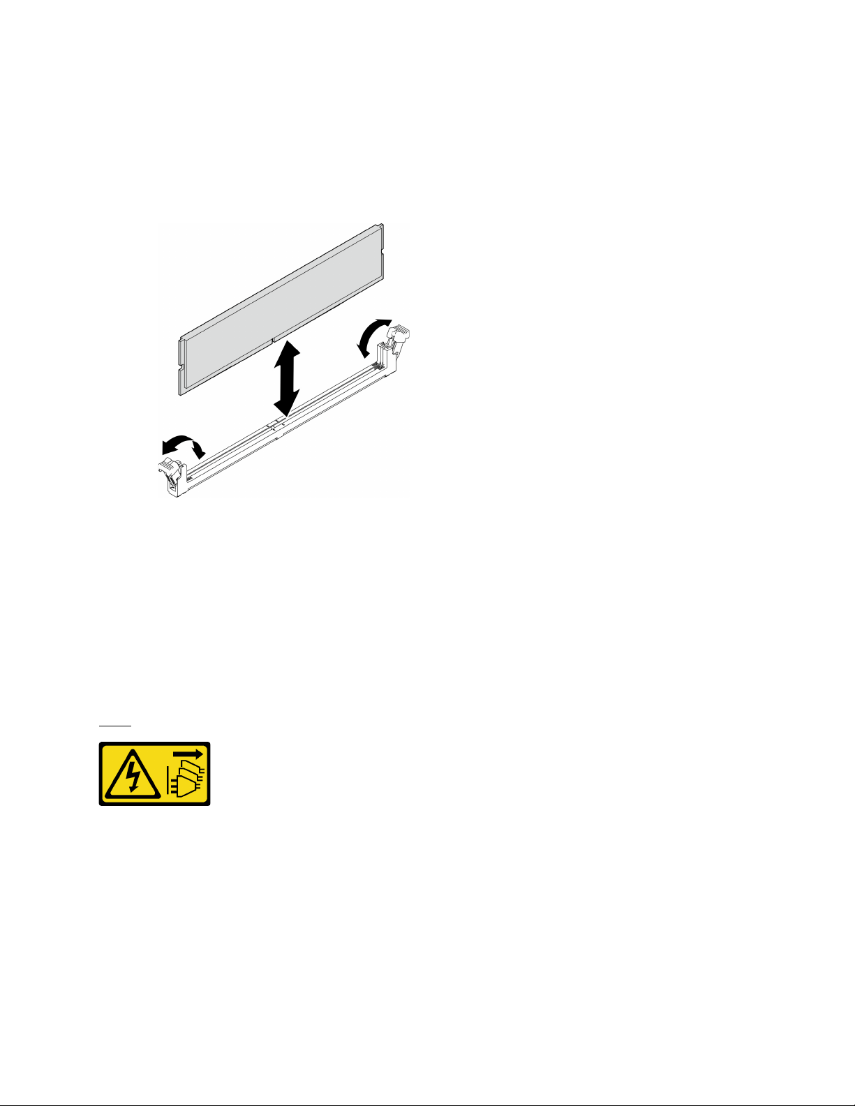
Note: The heat sink and processor could be very hot. To avoid burning yourself, wait for a few
minutes after turning off the server before you remove the server cover.
b. If the optical drive cage is installed, remove it from the chassis, see
“Remove the optical drive
cage” on page 76
.
Step 2. Carefully open the retaining clips on both ends of the memory module slot; then, gently lift the
memory module to remove it.
Figure 89. Removing a memory module
After you finish
1. Install a new memory module if necessary. See
“Install a memory module” on page 113.
2. If you are instructed to return the component or optional device, follow all packaging instructions, and
use any packaging materials for shipping that are supplied to you.
Install a memory module
Follow this procedure to install a memory module.
S002
CAUTION:
The power-control button on the device and the power switch on the power supply do not turn off the
electrical current supplied to the device. The device also might have more than one power cord. To
remove all electrical current from the device, ensure that all power cords are disconnected from the
power source.
About this task
Important: Ensure that you consider and follow the memory module installation rules when performing the
operation, see “Memory module installation rules” section in Setup Guide.
Chapter 3. Hardware replacement procedures 113
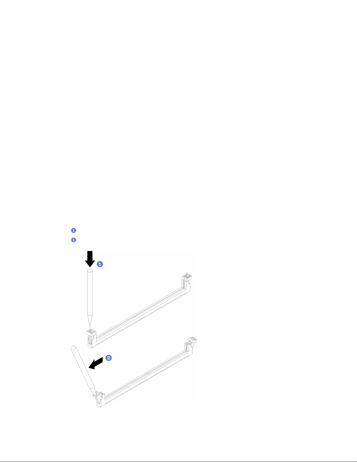
Attention:
• Read
“Safety inspection checklist” on page iv and “Installation guidelines” on page 41 to ensure that you
work safely.
• Touch the static-protective package that contains the component to any unpainted metal surface on the
server; then, remove it from the package and place it on a static-protective surface.
Memory modules are sensitive to static discharge and require special handling. In addition to the standard
guidelines of
“Handling static-sensitive devices” on page 43:
• Always wear an electrostatic-discharge strap when removing or installing memory modules. Electrostatic-
discharge gloves can also be used.
• Keep each memory module separated from one another. Do not stack memory modules directly on top of
each other during storage.
• Keep the gold memory module connector contacts from touching anything.
• Handle memory modules with care: never bend, twist, or drop a memory module.
Watch the procedure
A video of this procedure is available at YouTube:
https://www.youtube.com/playlist?list=PLYV5R7hVcs-
AU3iY3F7lq3qfqr5caGbIu
.
About this task
Step 1. Locate the memory module slots and determine memory module installation order based on
“Memory module installation rules” on page 44.
Step 2. Make sure that both retaining clips on the memory module connector are in the open position.
a.
With the tip of a pointed tool, carefully press the retaining clips.
b.
Push the retaining clips outward on each end of the memory module slot.
Figure 90. Opening the memory module retaining clips
114 ThinkSystem ST50 V2 Maintenance Manual

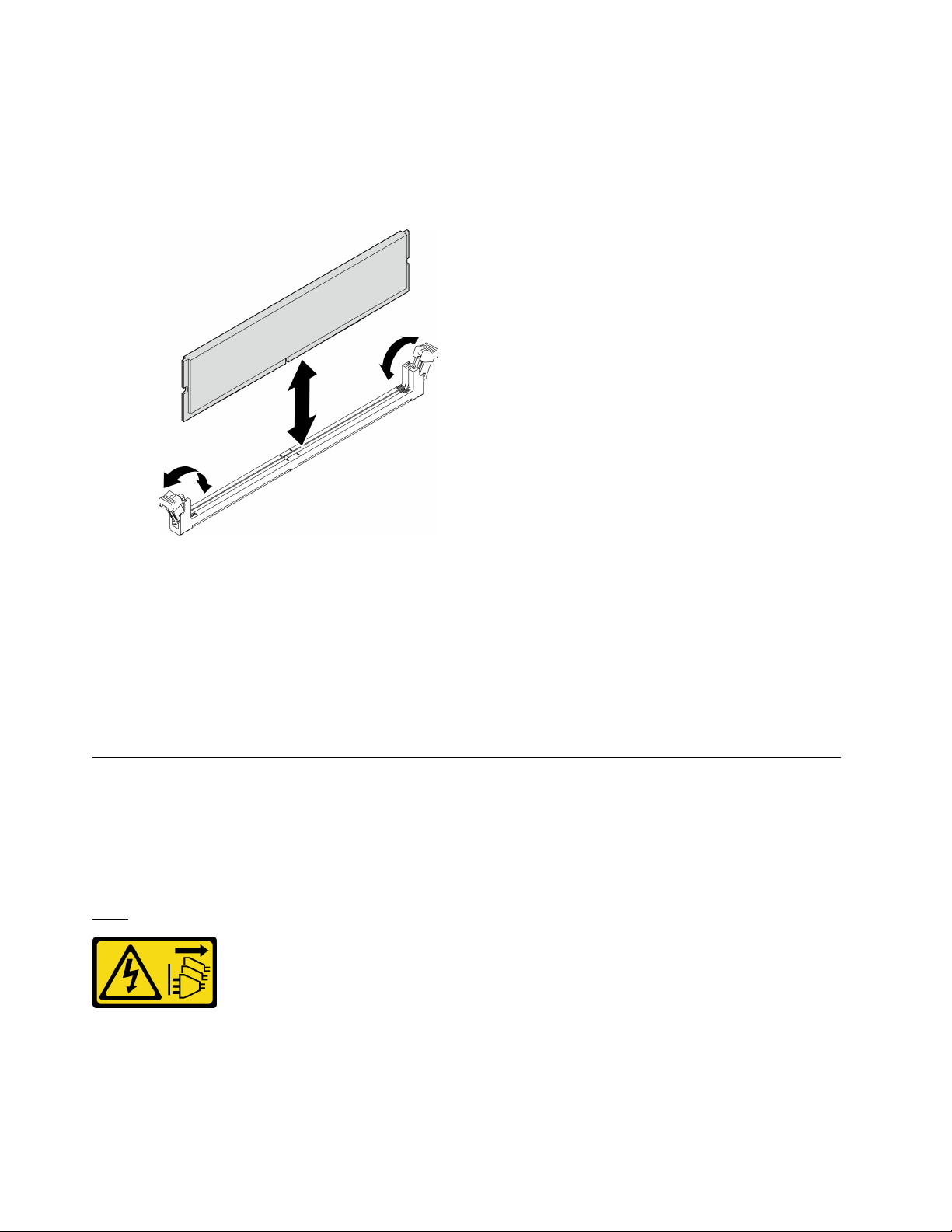
Step 3. Align the memory module with the slot; then, press the memory module into the slot with even
pressure on both ends of the memory module until the retaining clips snap into the locked position.
Note: Make sure that the small tabs on the retaining clips engage with the notches on the memory
module. If there is a gap between the memory module and the retaining clips, it indicates that the
memory module has not been properly installed. Remove the memory module and reinstall it.
Figure 91. Installing a memory module
After you finish
1. Install other memory modules if necessary.
2. If the optical drive cage was removed, reinstall it to the chassis, see
“Install the optical drive cage” on
page 78
.
3. Reconfigure the memory module if necessary.
4. Proceed to complete the parts replacement, see
“Complete the parts replacement” on page 158.
Mono amplifier (speaker) replacement
Follow this procedure to remove and install the mono amplifier (speaker).
Remove the mono amplifier (speaker)
Follow this procedure to remove the mono amplifier (speaker).
S002
CAUTION:
The power-control button on the device and the power switch on the power supply do not turn off the
electrical current supplied to the device. The device also might have more than one power cord. To
remove all electrical current from the device, ensure that all power cords are disconnected from the
power source.
116
ThinkSystem ST50 V2 Maintenance Manual

About this task
Attention:
• Read
“Safety inspection checklist” on page iv and “Installation guidelines” on page 41 to ensure that you
work safely.
• Turn off the server and peripheral devices, and disconnect the power cords and all external cables, see
“Power off the server” on page 9.
• If the server is in a rack, remove it from the rack. See
“Remove the server from the rails” on page 138.
• Remove any locking device that secures the server, such as a Kensington lock or a padlock.
• Place the server on its side with the cover up.
Watch the procedure
A video of this procedure is available at YouTube:
https://www.youtube.com/playlist?list=PLYV5R7hVcs-
AU3iY3F7lq3qfqr5caGbIu
.
Procedure
Step 1. Make preparation for this task.
a. Remove the server cover, see
“Remove the server cover” on page 144.
Note: The heat sink and processor could be very hot. To avoid burning yourself, wait for a few
minutes after turning off the server before you remove the server cover.
Step 2. Disconnect the mono amplifier cable from the system board.
Chapter 3. Hardware replacement procedures 117
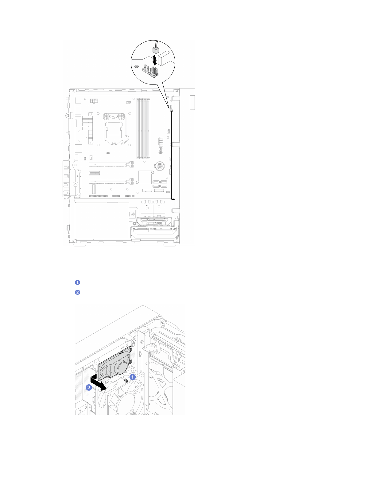
Figure 92. Disconnecting the mono amplifier cable
Step 3. Remove the mono amplifier.
a.
Remove the screw that secures the mono amplifier to the chassis.
b.
Slide out the mono amplifier from the bracket, and remove it from the chassis.
Figure 93. Removing the mono amplifier
After you finish
118 ThinkSystem ST50 V2 Maintenance Manual

1. Install a new mono amplifier, see “Install the mono amplifier (speaker)” on page 119.
2. If you are instructed to return the component or optional device, follow all packaging instructions, and
use any packaging materials for shipping that are supplied to you.
Install the mono amplifier (speaker)
Follow this procedure to install the mono amplifier (speaker).
S002
CAUTION:
The power-control button on the device and the power switch on the power supply do not turn off the
electrical current supplied to the device. The device also might have more than one power cord. To
remove all electrical current from the device, ensure that all power cords are disconnected from the
power source.
About this task
Attention:
1. Read
“Safety inspection checklist” on page iv and “Installation guidelines” on page 41 to ensure that you
work safely.
2. Touch the static-protective package that contains the component to any unpainted metal surface on the
server; then, remove it from the package and place it on a static-protective surface.
Watch the procedure
A video of this procedure is available at YouTube:
https://www.youtube.com/playlist?list=PLYV5R7hVcs-
AU3iY3F7lq3qfqr5caGbIu
.
Procedure
Step 1. Install the mono amplifier.
a.
Insert the mono amplifier into the bracket on the inside of the chassis.
b.
Fasten the screw to secure the mono amplifier to the chassis.
Chapter 3. Hardware replacement procedures 119

Figure 94. Installing the mono amplifier
Step 2. Connect the mono amplifier cable to the system board, see
“Internal cable routing” on page 19.
After you finish
Proceed to complete the parts replacement, see
“Complete the parts replacement” on page 158.
PCIe adapter replacement
Follow this procedure to remove and install a PCIe adapter.
This server comes with three PCIe slots. The adapter can be Ethernet, host bus, RAID, graphics, or any other
types that are supported, but the installation and removal procedures are the same.
Note: For a list of the supported PCIe adapters, see:
https://static.lenovo.com/us/en/serverproven/index.shtml
Remove a PCIe adapter
Follow this procedure to remove a PCIe adapter.
S002
CAUTION:
The power-control button on the device and the power switch on the power supply do not turn off the
electrical current supplied to the device. The device also might have more than one power cord. To
remove all electrical current from the device, ensure that all power cords are disconnected from the
power source.
About this task
Attention:
120
ThinkSystem ST50 V2 Maintenance Manual
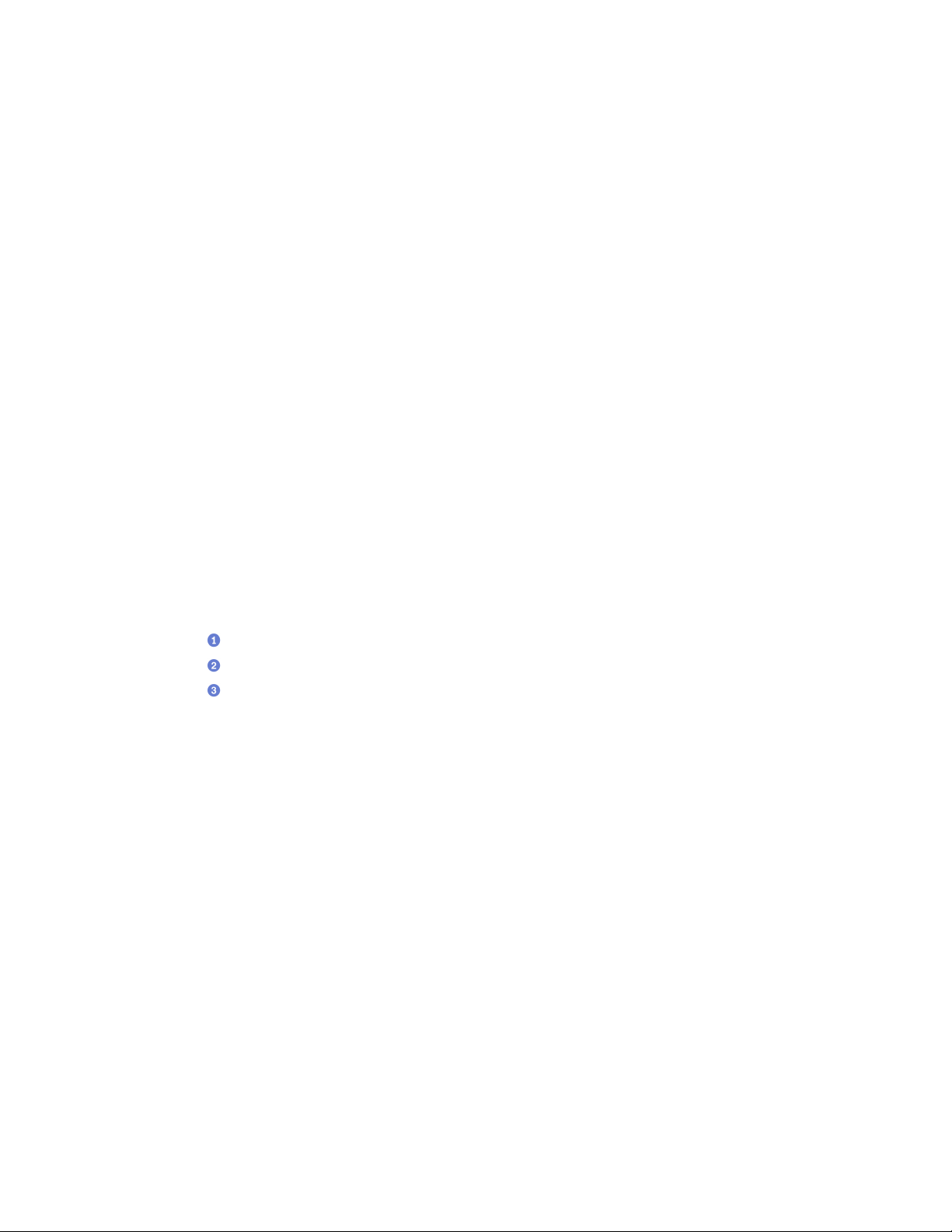
• Read “Safety inspection checklist” on page iv and “Installation guidelines” on page 41 to ensure that you
work safely.
• Turn off the server and peripheral devices, and disconnect the power cords and all external cables, see
“Power off the server” on page 9.
• If the server is in a rack, remove it from the rack. See
“Remove the server from the rails” on page 138.
• Remove any locking device that secures the server, such as a Kensington lock or a padlock.
• Place the server on its side with the cover up.
Notes:
• The PCIe adapter might look different from the illustration.
• Make sure to read and follow the documentation that comes with the PCIe adapter.
Watch the procedure
A video of this procedure is available at YouTube:
https://www.youtube.com/playlist?list=PLYV5R7hVcs-
AU3iY3F7lq3qfqr5caGbIu
.
Procedure
Step 1. Make preparation for this task.
a. Remove the server cover, see
“Remove the server cover” on page 144.
Note: The heat sink and processor could be very hot. To avoid burning yourself, wait for a few
minutes after turning off the server before you remove the server cover.
Step 2. Disconnect all PCIe adapter cables from the system board.
Step 3. Remove the PCIe adapter
a.
Rotate the PCIe adapter retainer clip to the open position.
b.
Press the retaining clip to release the PCIe adapter.
c.
Grasp the PCIe adapter by both edges, and gently lift it out from the PCIe slot.
Note: The PCIe adapter might be clamped by the slot tightly. In this case, gently and evenly
shake the PCIe adapter until the clamping force from the connector is significantly reduced
and the adapter becomes easily removable.
Chapter 3. Hardware replacement procedures 121
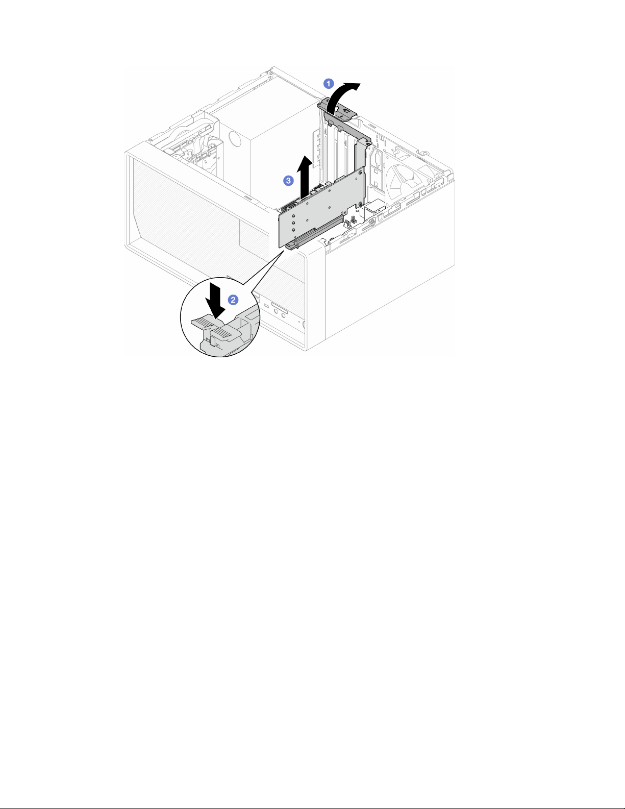
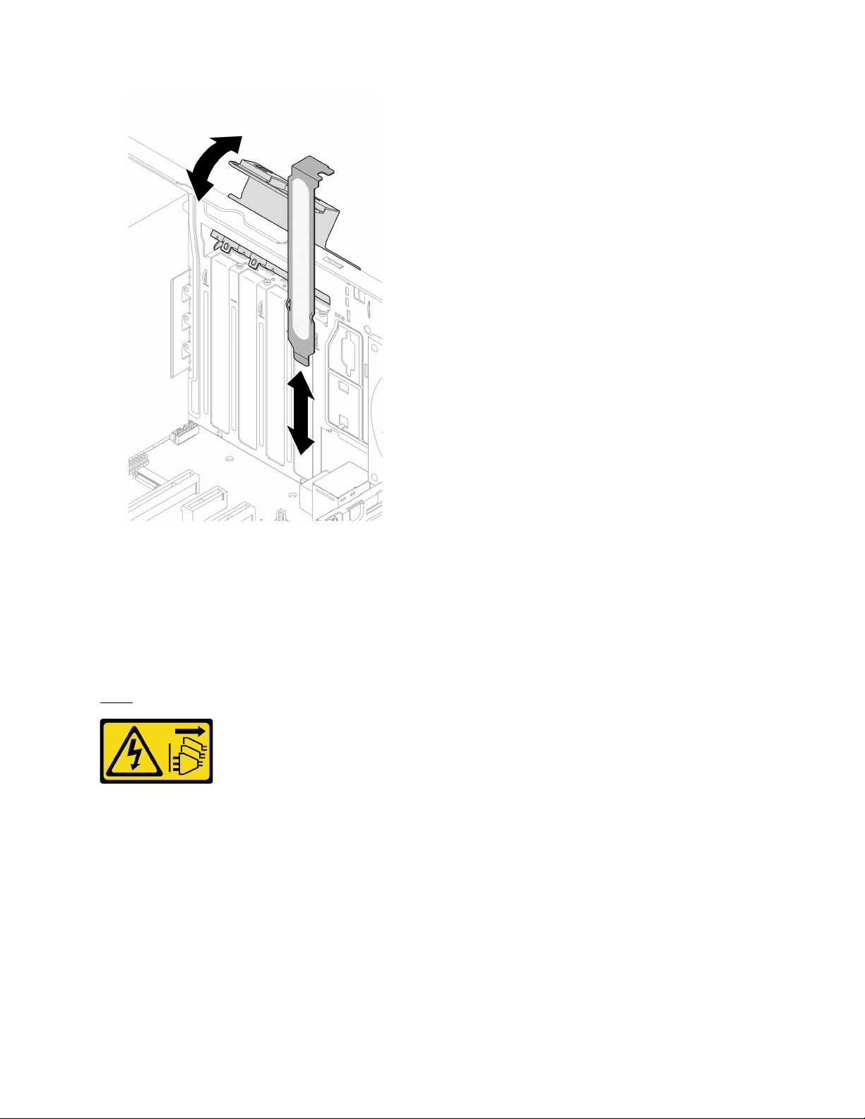
Figure 96. Installing a PCIe adapter bracket
2. If you are instructed to return the component or optional device, follow all packaging instructions, and
use any packaging materials for shipping that are supplied to you.
Install a PCIe adapter
Follow this procedure to install a PCIe adapter.
S002
CAUTION:
The power-control button on the device and the power switch on the power supply do not turn off the
electrical current supplied to the device. The device also might have more than one power cord. To
remove all electrical current from the device, ensure that all power cords are disconnected from the
power source.
About this task
Attention:
• Read
“Safety inspection checklist” on page iv and “Installation guidelines” on page 41 to ensure that you
work safely.
Chapter 3. Hardware replacement procedures 123

• Touch the static-protective package that contains the component to any unpainted metal surface on the
server; then, remove it from the package and place it on a static-protective surface.
Notes:
• The PCIe adapter might look different from the illustration.
• Make sure to read and follow the documentation that comes with the PCIe adapter.
PCIe slot support
• PCIe slot 1: PCI Express 4.0 x16 (FHHL 75W PCIe adapter)
• PCIe slot 2: PCI Express 3.0 x1 (FHHL, 25W PCIe adapter)
• PCIe slot 3: PCI Express 3.0 x4 in x16 slot (FHHL, 25W PCIe adapter)
Notes:
• The RAID adapter should be installed in PCIe slot 1.
• Pentium processor supports up to PCI Express 3.0.
• When installing PCIe x8/x16 adapter to PCIe Slot 3, the PCIe adapter performance might be degraded
due to the bandwidth of PCIe slot 3 (x4).
• For a list of the supported PCIe adapters, see
https://static.lenovo.com/us/en/serverproven/index.shtml.
• The PCIe adapter might look different from the illustration.
• Make sure to read and follow the documentation that comes with the PCIe adapter.
Watch the procedure
A video of this procedure is available at YouTube:
https://www.youtube.com/playlist?list=PLYV5R7hVcs-
AU3iY3F7lq3qfqr5caGbIu
.
About this task
Step 1. If a bracket is installed in the chassis, open the PCIe adapter retainer bracket and remove the
bracket from the chassis. Keep the bracket for future use.
124
ThinkSystem ST50 V2 Maintenance Manual
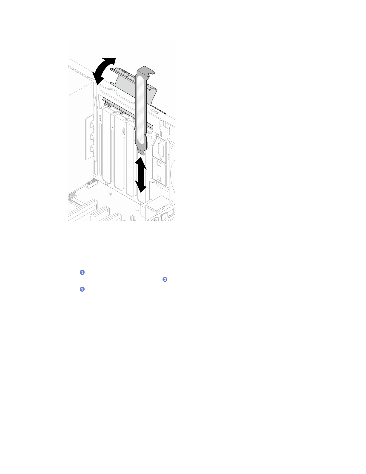
Figure 97. Removing a PCIe adapter bracket
Step 2. Locate the applicable PCIe slot. For more information about the PCIe slots, see
“Specifications” on
page 2
.
Step 3. Install the PCIe adapter.
a.
Align the PCIe adapter to the slot; then, gently press both ends of the PCIe adapter until it is
securely seated in the slot with
the retaining clip clicks into the locked position.
b.
Rotate the PCIe adapter retainer towards the chassis until it snaps into locked position.
Chapter 3. Hardware replacement procedures 125
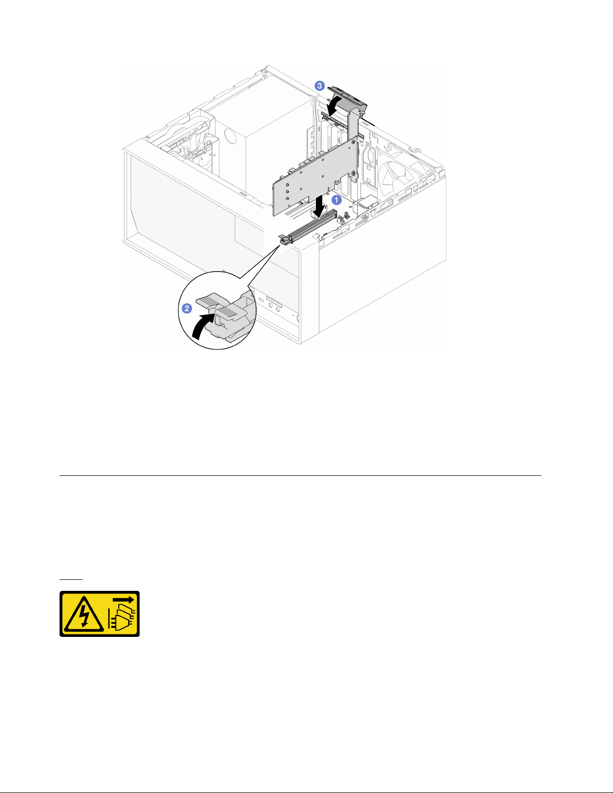
Figure 98. Installing a PCIe adapter
Step 4. Connect the PCIe adapter cables. For more information on RAID adapter cable routing, see
“Internal cable routing” on page 19.
After you finish
Proceed to complete the parts replacement, see “Complete the parts replacement” on page 158.
Power button with LED replacement
Follow this procedure to remove and install the power button with LED.
Remove the power button with LED
Follow this procedure to remove the power button with LED.
S002
CAUTION:
The power-control button on the device and the power switch on the power supply do not turn off the
electrical current supplied to the device. The device also might have more than one power cord. To
remove all electrical current from the device, ensure that all power cords are disconnected from the
power source.
126
ThinkSystem ST50 V2 Maintenance Manual

About this task
Attention:
• Read
“Safety inspection checklist” on page iv and “Installation guidelines” on page 41 to ensure that you
work safely.
• Turn off the server and peripheral devices, and disconnect the power cords and all external cables, see
“Power off the server” on page 9.
• If the server is in a rack, remove it from the rack. See
“Remove the server from the rails” on page 138.
• Remove any locking device that secures the server, such as a Kensington lock or a padlock.
• Place the server on its side with the cover up.
Watch the procedure
A video of this procedure is available at YouTube:
https://www.youtube.com/playlist?list=PLYV5R7hVcs-
AU3iY3F7lq3qfqr5caGbIu
.
Procedure
Step 1. Make preparation for this task.
a. Remove the server cover, see
“Remove the server cover” on page 144.
Note: The heat sink and processor could be very hot. To avoid burning yourself, wait for a few
minutes after turning off the server before you remove the server cover.
b. Remove the front bezel, see
“Remove the front bezel” on page 84.
c. Remove the front panel, see
“Remove the front panel” on page 87.
Step 2. Remove the power button with LED from the front panel.
a.
Press the release tab on the power button to release it from the front panel.
b.
Remove the power button from the front panel.
Figure 99. Removing the power button with LED
After you finish
1. Install a new power button, see “Install the power button with LED” on page 128.
2. If you are instructed to return the component or optional device, follow all packaging instructions, and
use any packaging materials for shipping that are supplied to you.
Chapter 3. Hardware replacement procedures 127
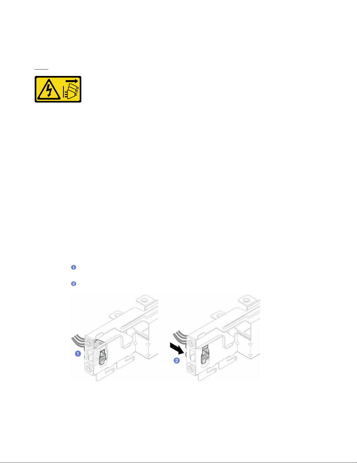
Install the power button with LED
Follow this procedure to install the power button with LED.
S002
CAUTION:
The power-control button on the device and the power switch on the power supply do not turn off the
electrical current supplied to the device. The device also might have more than one power cord. To
remove all electrical current from the device, ensure that all power cords are disconnected from the
power source.
About this task
Attention:
1. Read
“Safety inspection checklist” on page iv and “Installation guidelines” on page 41 to ensure that you
work safely.
2. Touch the static-protective package that contains the component to any unpainted metal surface on the
server; then, remove it from the package and place it on a static-protective surface.
Watch the procedure
A video of this procedure is available at YouTube:
https://www.youtube.com/playlist?list=PLYV5R7hVcs-
AU3iY3F7lq3qfqr5caGbIu
.
Procedure
Step 1. Install the power button with LED.
a.
Tilt the power button, and insert the tab on the bottom of the power button cable into the
slot.
b.
Push the power button into the slot until it snaps into place.
Figure 100. Installing the power button with LED
Step 2. Reinstall the front panel, see “Install the front panel” on page 91.
Step 3. Connect the power button cable to the system board, see “Internal cable routing” on page 19.
128 ThinkSystem ST50 V2 Maintenance Manual
After you finish
1. Reinstall the front bezel, see
“Install the front bezel” on page 86.
2. Proceed to complete the parts replacement, see “Complete the parts replacement” on page 158.
Power supply unit replacement
Follow this procedure to remove and install the fixed power supply unit.
This server supports one unit of fixed power supply of the following types:
• 300-watt
• 500-watt
Remove the power supply unit
Follow this procedure to remove the power supply unit.
S001
DANGER
Electrical current from power, telephone, and communication cables is hazardous.
To avoid a shock hazard:
• Connect all power cords to a properly wired and grounded electrical outlet/source.
• Connect any equipment that will be attached to this product to properly wired outlets/sources.
• When possible, use one hand only to connect or disconnect signal cables.
• Never turn on any equipment when there is evidence of fire, water, or structural damage.
• The device might have more than one power cord, to remove all electrical current from the
device, ensure that all power cords are disconnected from the power source.
S002
CAUTION:
The power-control button on the device and the power switch on the power supply do not turn off the
electrical current supplied to the device. The device also might have more than one power cord. To
remove all electrical current from the device, ensure that all power cords are disconnected from the
power source.
Chapter 3. Hardware replacement procedures 129

S035
CAUTION:
Never remove the cover on a power supply or any part that has this label attached. Hazardous voltage,
current, and energy levels are present inside any component that has this label attached. There are no
serviceable parts inside these components. If you suspect a problem with one of these parts, contact
a service technician.
About this task
Attention:
• Read
“Safety inspection checklist” on page iv and “Installation guidelines” on page 41 to ensure that you
work safely.
• Turn off the server and peripheral devices, and disconnect the power cords and all external cables, see
“Power off the server” on page 9.
• If the server is in a rack, remove it from the rack. See
“Remove the server from the rails” on page 138.
• Remove any locking device that secures the server, such as a Kensington lock or a padlock.
• Place the server on its side with the cover up.
Watch the procedure
A video of this procedure is available at YouTube:
https://www.youtube.com/playlist?list=PLYV5R7hVcs-
AU3iY3F7lq3qfqr5caGbIu
.
Procedure
Step 1. Make preparation for this task.
a. Remove the server cover, see
“Remove the server cover” on page 144.
Note: The heat sink and processor could be very hot. To avoid burning yourself, wait for a few
minutes after turning off the server before you remove the server cover.
b. Remove bay 1 drive cage and bay 2 drive cage (if applicable), see
“Simple-swap drive and
drive cage (bay 1-2) replacement” on page 50
.
Step 2. Disconnect the power supply unit cable from the system board.
Step 3. From the outside of the chassis, remove the four screws that secure the power supply unit to the
chassis.
130
ThinkSystem ST50 V2 Maintenance Manual

Figure 101. Removing the screws securing power supply units to chassis
Step 4. Remove the power supply unit from the chassis.
a.
Press the release tab to disengage the power supply from the chassis.
b.
Slide out the power supply unit; then, lift it out of the chassis.
Figure 102. Removing the power supply unit
After you finish
Chapter 3. Hardware replacement procedures 131
1. Install another power supply unit, see “Install the power supply unit” on page 132.
2. If you are instructed to return the component or optional device, follow all packaging instructions, and
use any packaging materials for shipping that are supplied to you.
Install the power supply unit
Follow this procedure to install the power supply unit.
S001
DANGER
Electrical current from power, telephone, and communication cables is hazardous.
To avoid a shock hazard:
• Connect all power cords to a properly wired and grounded electrical outlet/source.
• Connect any equipment that will be attached to this product to properly wired outlets/sources.
• When possible, use one hand only to connect or disconnect signal cables.
• Never turn on any equipment when there is evidence of fire, water, or structural damage.
• The device might have more than one power cord, to remove all electrical current from the
device, ensure that all power cords are disconnected from the power source.
S002
CAUTION:
The power-control button on the device and the power switch on the power supply do not turn off the
electrical current supplied to the device. The device also might have more than one power cord. To
remove all electrical current from the device, ensure that all power cords are disconnected from the
power source.
S035
CAUTION:
Never remove the cover on a power supply or any part that has this label attached. Hazardous voltage,
current, and energy levels are present inside any component that has this label attached. There are no
serviceable parts inside these components. If you suspect a problem with one of these parts, contact
a service technician.
132
ThinkSystem ST50 V2 Maintenance Manual
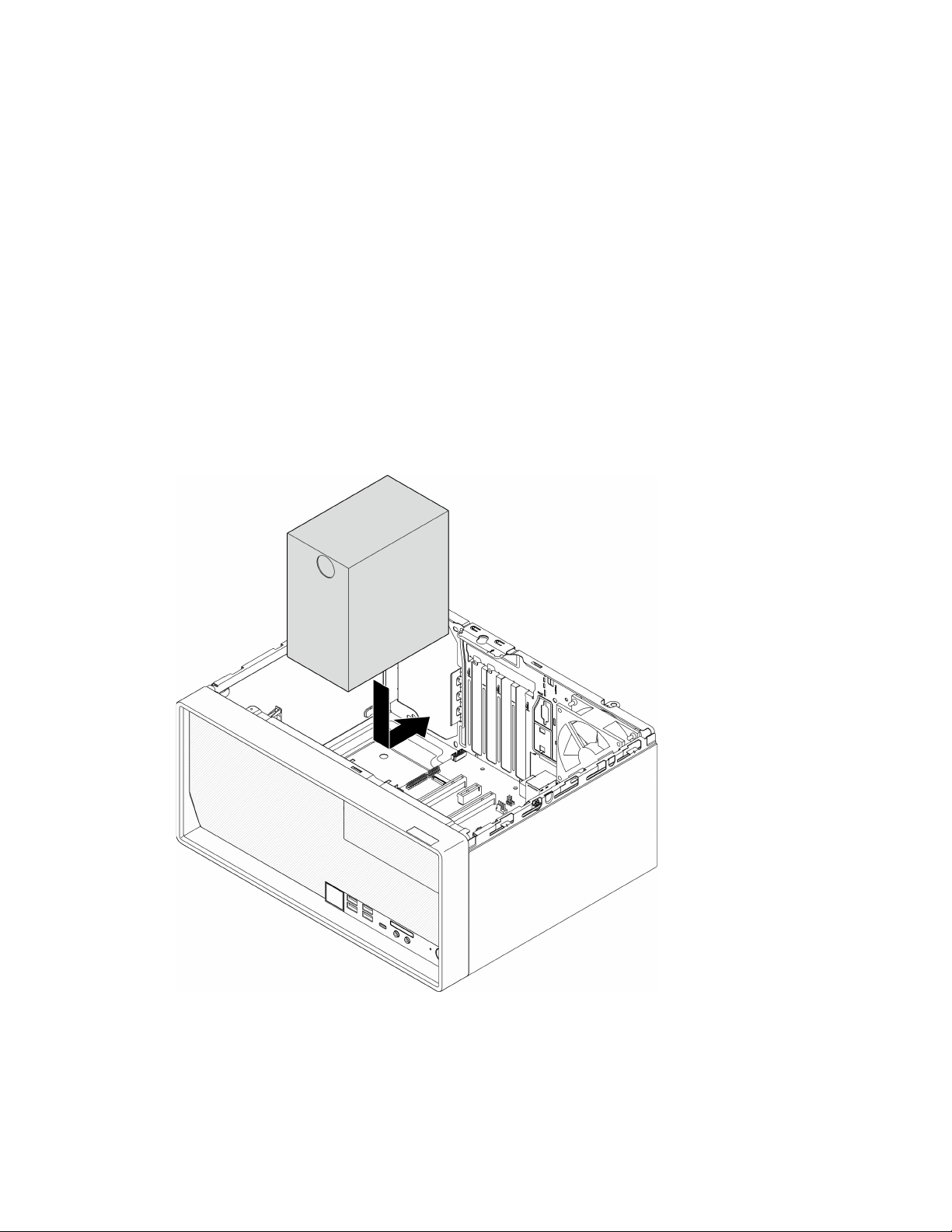
About this task
Attention:
• Read
“Safety inspection checklist” on page iv and “Installation guidelines” on page 41 to ensure that you
work safely.
• Touch the static-protective package that contains the component to any unpainted metal surface on the
server; then, remove it from the package and place it on a static-protective surface.
• Make sure the type of power supply is applicable to server drive configuration. See
“Specifications” on
page 2
for more information.
Watch the procedure
A video of this procedure is available at YouTube:
https://www.youtube.com/playlist?list=PLYV5R7hVcs-
AU3iY3F7lq3qfqr5caGbIu
.
Procedure
Step 1. Lower the power supply into the chassis, and slide it toward the opening on the rear side of chassis
until the release tab snaps into place.
Figure 103. Installing the power supply to the chassis
Step 2. From outside of the chassis, fasten the four screws to secure the power supply unit to the chassis.
Chapter 3. Hardware replacement procedures 133
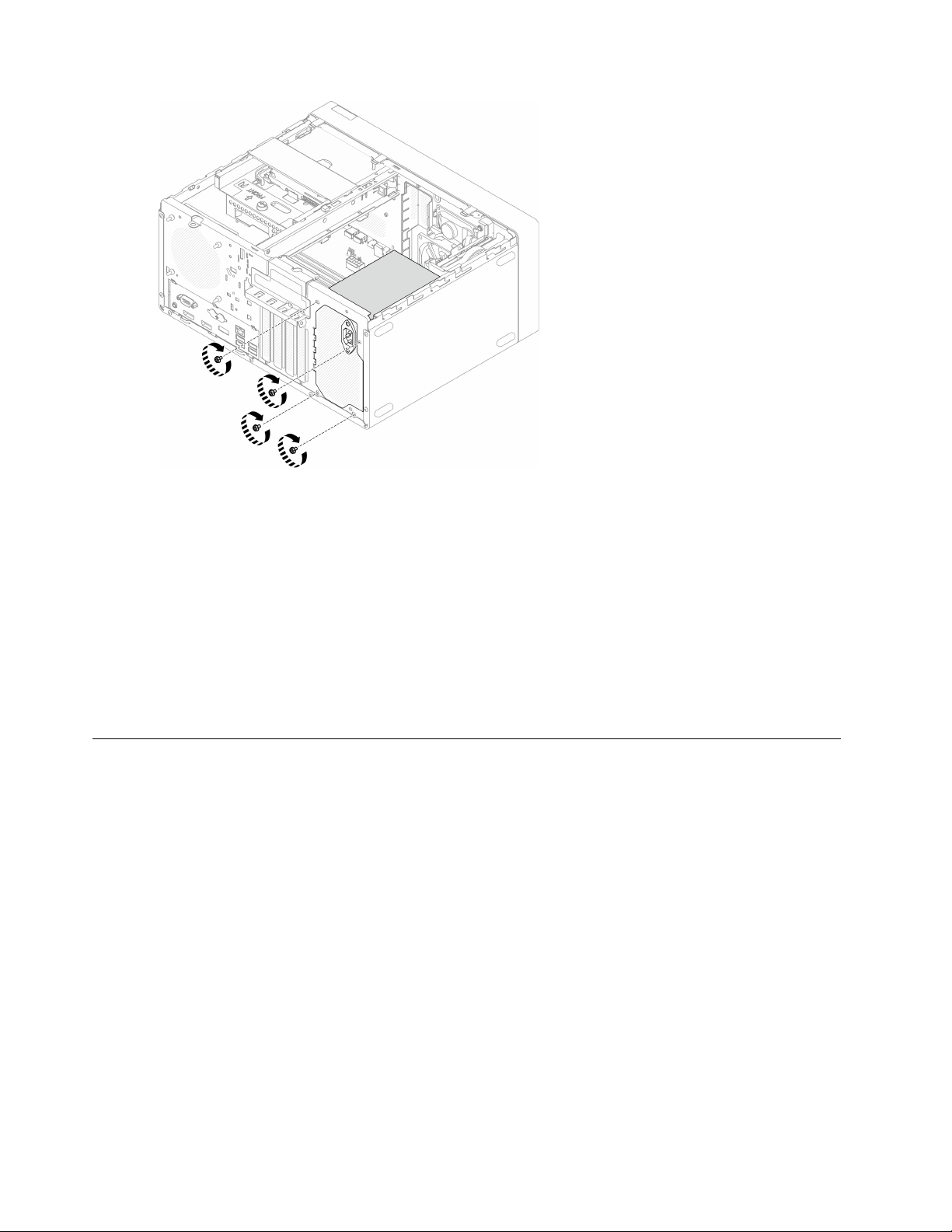
Figure 104. Securing the power supply units to the chassis
Step 3. Connect the processor and system power cables to the system board, see
“Internal cable routing”
on page 19
.
After you finish
1. Reinstall bay 1 drive cage and the 3.5-inch drive, see
“Simple-swap drive and drive cage (bay 1-2)
replacement” on page 50
.
2. If applicable, reinstall bay 2 drive cage and the 2.5-inch drive, see
“Simple-swap drive and drive cage
(bay 1-2) replacement” on page 50
.
3. Proceed to complete the parts replacement, see
“Complete the parts replacement” on page 158.
Processor replacement (trained technician only)
Use the following procedures to remove and install a processor. This procedure must be executed by a
trained technician.
Attention: Before you begin replacing a processor, make sure that you have an alcohol cleaning pad (part
number 00MP352) and gray thermal grease (part number 41Y9292).
Remove the processor (trained technician only)
Follow this procedure to remove the processor. This procedure must be executed by a trained technician.
134
ThinkSystem ST50 V2 Maintenance Manual
S002
CAUTION:
The power-control button on the device and the power switch on the power supply do not turn off the
electrical current supplied to the device. The device also might have more than one power cord. To
remove all electrical current from the device, ensure that all power cords are disconnected from the
power source.
About this task
Attention:
• Read
“Safety inspection checklist” on page iv and “Installation guidelines” on page 41 to ensure that you
work safely.
• Turn off the server and peripheral devices, and disconnect the power cords and all external cables, see
“Power off the server” on page 9.
• If the server is in a rack, remove it from the rack. See
“Remove the server from the rails” on page 138.
• Remove any locking device that secures the server, such as a Kensington lock or a padlock.
• Place the server on its side with the cover up.
Watch the procedure
A video of this procedure is available at YouTube:
https://www.youtube.com/playlist?list=PLYV5R7hVcs-
AU3iY3F7lq3qfqr5caGbIu
.
Procedure
Step 1. Make preparation for this task.
a. Remove the server cover, see
“Remove the server cover” on page 144.
Note: The heat sink and processor could be very hot. To avoid burning yourself, wait for a few
minutes after turning off the server before you remove the server cover.
b. If applicable, remove the optical drive cage, see
“Remove the optical drive cage” on page 76.
c. Remove the heat sink and fan module, see
“Remove the heat sink and fan module (trained
technician only)” on page 93
.
Step 2. Remove the processor.
a.
Gently pull the handle away from the processor retainer.
b.
Lift the handle along with the retainer to the fully open position.
c.
Hold the processor by both sides and gently lift it away from the processor socket.
Attention:
1. Do not touch the gold contacts on the bottom of the processor.
2. Keep the processor socket clean from any object to prevent possible damages.
Chapter 3. Hardware replacement procedures 135
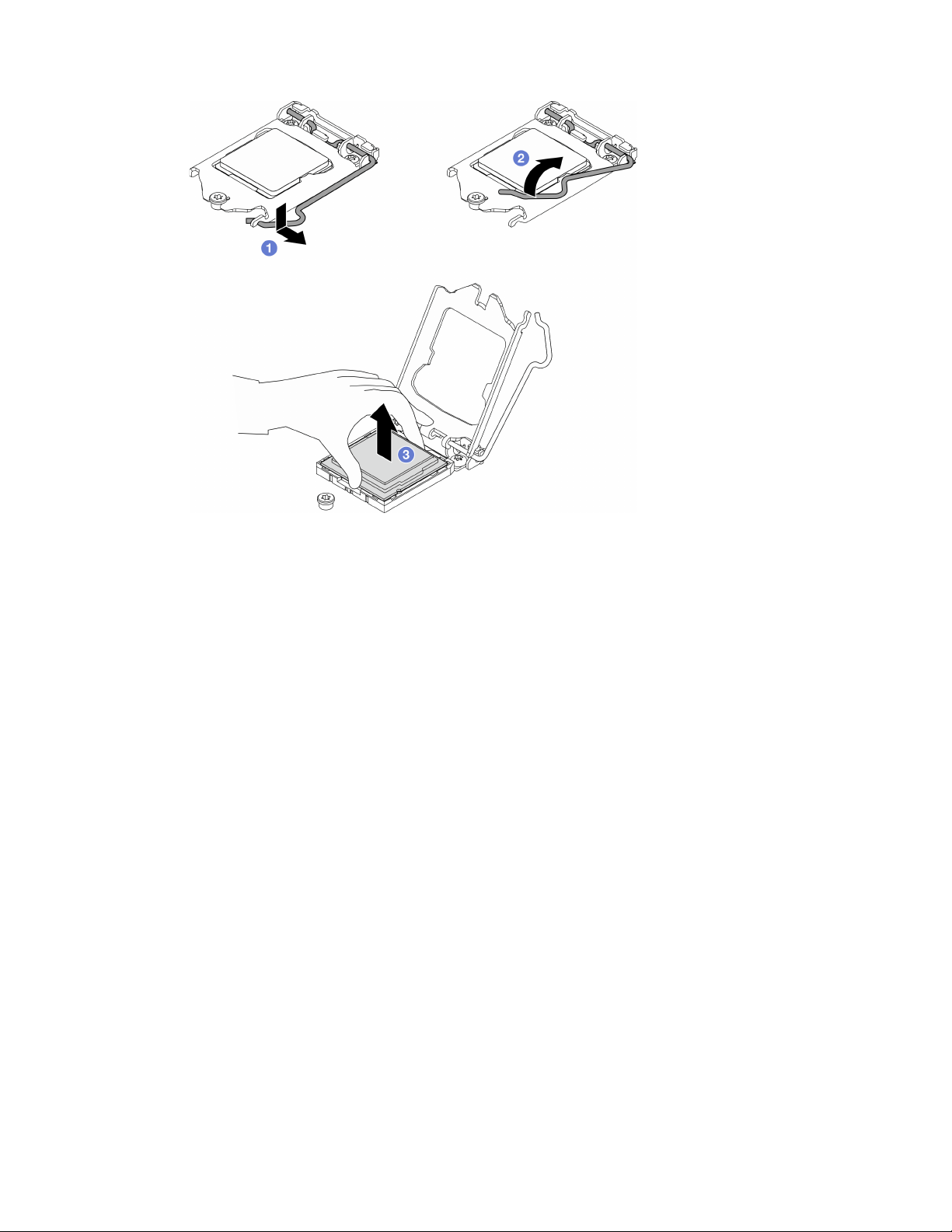
Figure 105. Removing the processor
After you finish
After removing the processor, perform one of the following tasks immediately:
• Install the replacement processor.
1. Install the replacement processor to the system board, see
“Install the processor (trained technician
only)” on page 136
.
2. Package the defective processor that was removed, and return it to Lenovo. To prevent any shipping
damage, reuse the packaging of the new processor, and follow all available packaging instructions.
or
• Install the processor that you removed to the replacement system board.
1. Install the removed processor to the replacement system board, see
“Install the processor (trained
technician only)” on page 136
.
2. Package the defective system board, and return it to Lenovo. To prevent any shipping damage, reuse
the packaging of the new system board, and follow all available packaging instructions.
Install the processor (trained technician only)
Follow this procedure to install the processor. This procedure must be executed by a trained technician.
136
ThinkSystem ST50 V2 Maintenance Manual
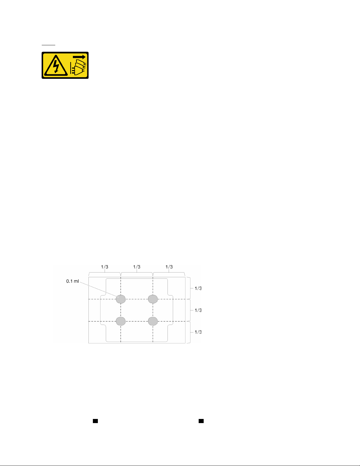
S002
CAUTION:
The power-control button on the device and the power switch on the power supply do not turn off the
electrical current supplied to the device. The device also might have more than one power cord. To
remove all electrical current from the device, ensure that all power cords are disconnected from the
power source.
About this task
Attention:
• Read
“Safety inspection checklist” on page iv and “Installation guidelines” on page 41 to ensure that you
work safely.
• Touch the static-protective package that contains the component to any unpainted metal surface on the
server; then, remove it from the package and place it on a static-protective surface.
Applying thermal grease
1. If the processor to be installed was removed from another system board, wipe the thermal grease from
the processor with an alcohol cleaning pad, and dispose of the cleaning pad after all of the thermal
grease is removed.
Note: If you are applying new thermal grease on the top of the processor, make sure to do it after the
alcohol has fully evaporated.
2. Apply the thermal grease on the top of the processor with syringe by forming four uniformly spaced
dots, while each dot consists of about 0.1 ml of thermal grease.
Figure 106. Proper shape of the thermal grease
Watch the procedure
A video of this procedure is available at YouTube:
https://www.youtube.com/playlist?list=PLYV5R7hVcs-
AU3iY3F7lq3qfqr5caGbIu
.
Procedure
Step 1. Hold the processor by both sides, and align the following:
1. Align
1 the small notches on the processor to 2 the tabs on the socket.
Chapter 3. Hardware replacement procedures 137
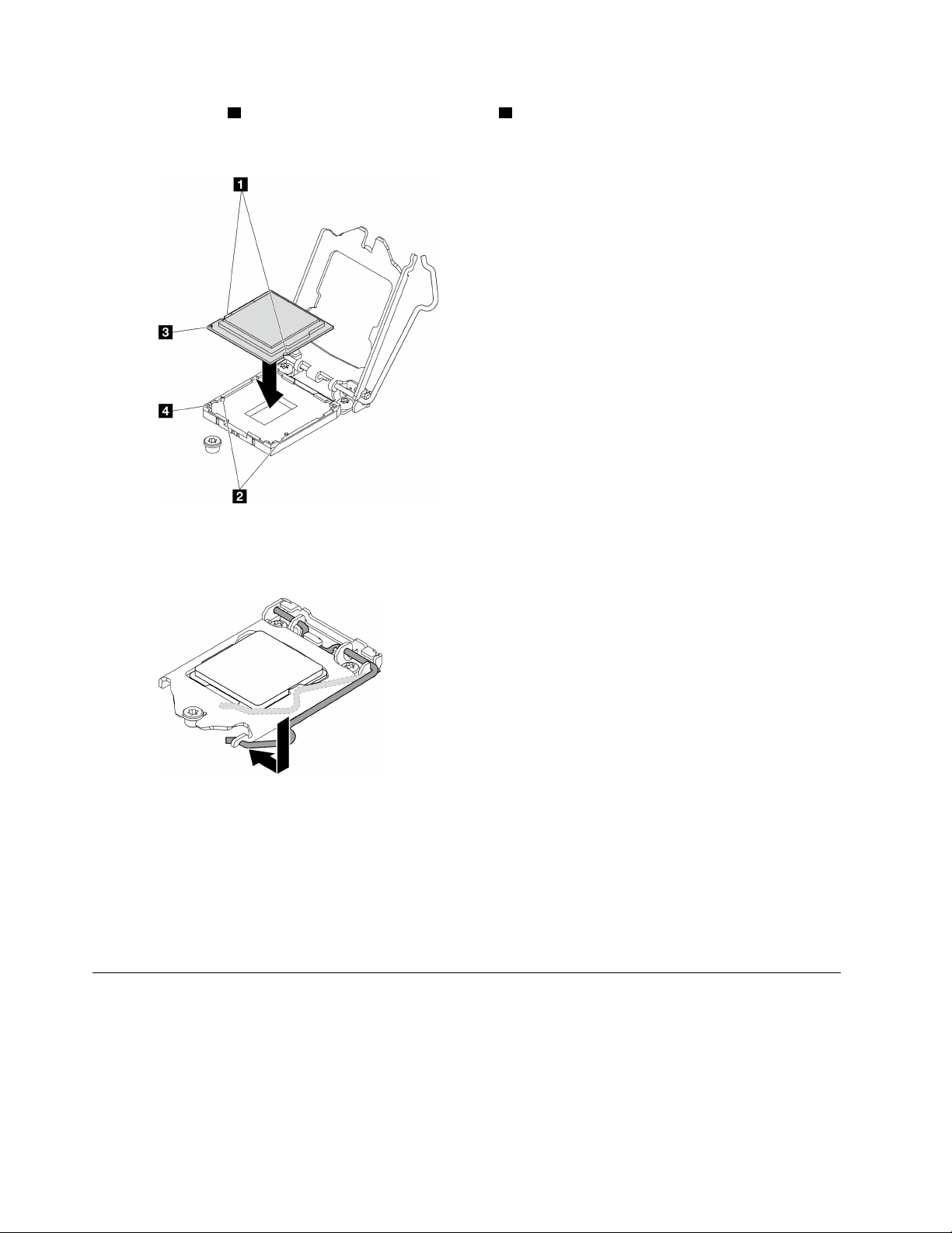
2. Align 3 the small triangle of the processor to 4 the beveled corner on the socket.
Then, gently lower the processor evenly into the socket.
Figure 107. Installing the processor
Step 2. Close the processor retainer, and push the handle to the locked position.
Figure 108. Closing the processor retainer
After you finish
1. Reinstall the heat sink and fan assembly, see
“Install the heat sink and the fan module (trained technician
only)” on page 97
.
2. If necessary, reinstall the optical drive cage, see
“Install the optical drive cage” on page 78.
3. Proceed to complete the parts replacement, see “Complete the parts replacement” on page 158.
Server replacement
Follow this procedure to remove the serve from rack or install the server to rack. This procedure must be
executed by a trained technician.
Remove the server from the rails
Follow this procedure to remove the server from the rails.
138
ThinkSystem ST50 V2 Maintenance Manual

S002
CAUTION:
The power-control button on the device and the power switch on the power supply do not turn off the
electrical current supplied to the device. The device also might have more than one power cord. To
remove all electrical current from the device, ensure that all power cords are disconnected from the
power source.
S014
CAUTION:
Hazardous voltage, current, and energy levels might be present. Only a qualified service technician is
authorized to remove the covers where the label is attached.
S033
CAUTION:
Hazardous energy present. Voltages with hazardous energy might cause heating when shorted with
metal, which might result in spattered metal, burns, or both.
About this task
Attention:
• Read
“Safety inspection checklist” on page iv and “Installation guidelines” on page 41 to ensure that you
work safely.
• Turn off the server and peripheral devices, and disconnect the power cords and all external cables, see
“Power off the server” on page 9.
Watch the procedure
A video of this procedure is available at YouTube:
https://www.youtube.com/playlist?list=PLYV5R7hVcs-
AU3iY3F7lq3qfqr5caGbIu
.
Procedure
Note: Your system might looks slightly different from the illustration below.
Step 1. Remove the two M6 x 16 screws on the front of the rack cabinet.
Chapter 3. Hardware replacement procedures 139
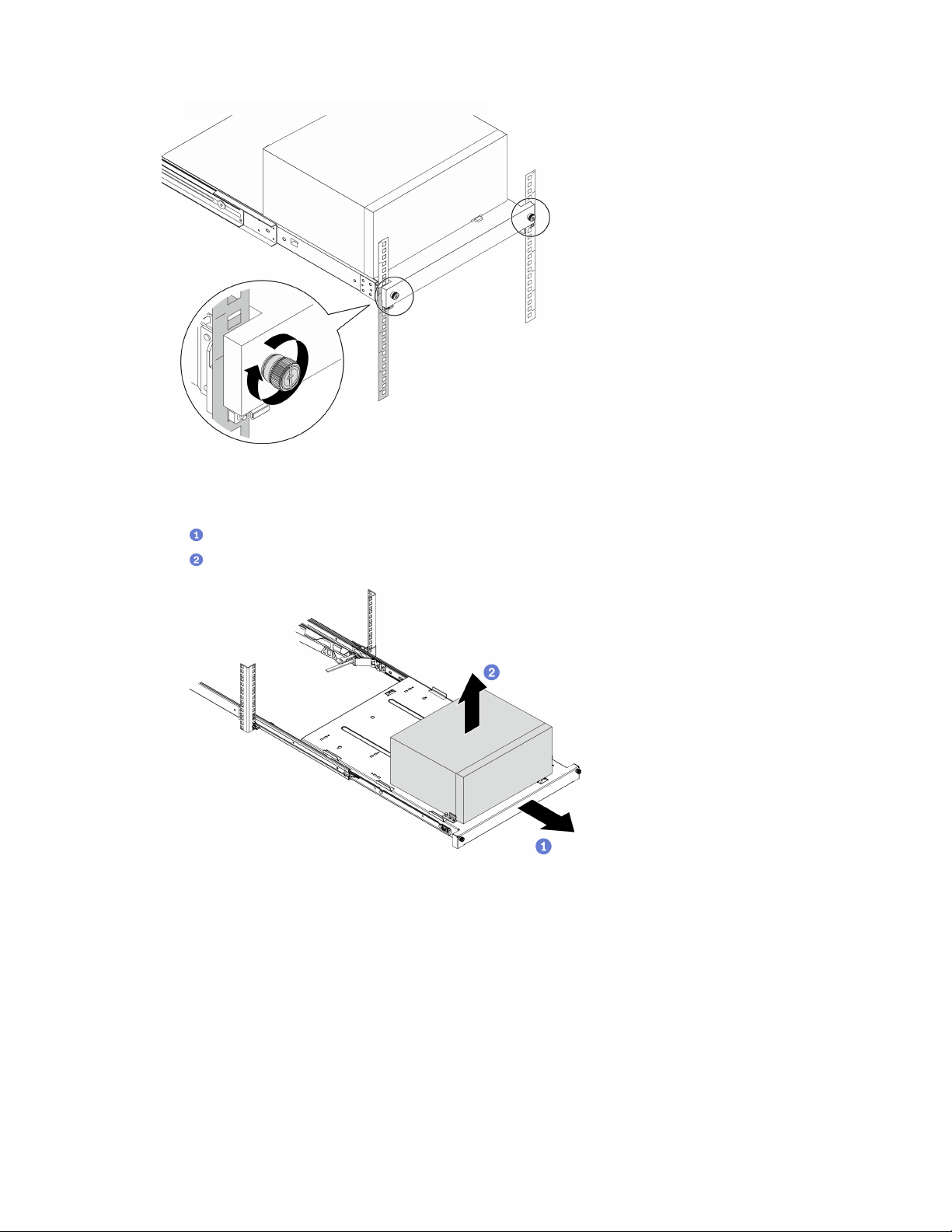
Figure 109. Removing the screws on the front of the rack cabinet
Step 2. Remove the server from the rails.
a.
Slide and pull the rack server tray out of the rack cabinet.
b.
Lift the server out of the tray.
Figure 110. Removing the server from the rails
After you finish
1. Place the server on its side with the cover up.
2. To install the server to the rails, see
“Install the server to the rails” on page 140.
Install the server to the rails
Follow this procedure to install the server to the rails.
140
ThinkSystem ST50 V2 Maintenance Manual
S002
CAUTION:
The power-control button on the device and the power switch on the power supply do not turn off the
electrical current supplied to the device. The device also might have more than one power cord. To
remove all electrical current from the device, ensure that all power cords are disconnected from the
power source.
S014
CAUTION:
Hazardous voltage, current, and energy levels might be present. Only a qualified service technician is
authorized to remove the covers where the label is attached.
S033
CAUTION:
Hazardous energy present. Voltages with hazardous energy might cause heating when shorted with
metal, which might result in spattered metal, burns, or both.
About this task
Attention:
• Read
“Safety inspection checklist” on page iv and “Installation guidelines” on page 41 to ensure that you
work safely.
• Turn off the server and peripheral devices, and disconnect the power cords and all external cables, see
“Power off the server” on page 9.
Note: To install rails to rack, see the Rail Installation Guide at
https://thinksystem.lenovofiles.com/help/topic/
rail_options/rail_options_tower_servers.html
.
Watch the procedure
A video of this procedure is available at YouTube:
https://www.youtube.com/playlist?list=PLYV5R7hVcs-
AU3iY3F7lq3qfqr5caGbIu
.
Procedure
Step 1. Install the four brackets to the tray as illustrated.
Chapter 3. Hardware replacement procedures 141
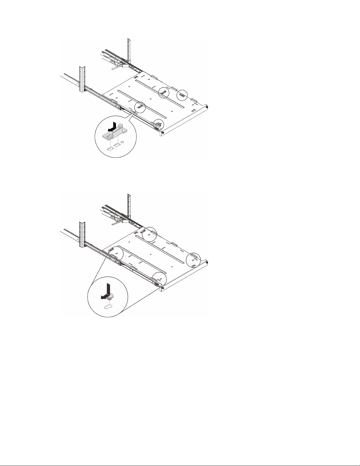
Figure 111. Installing the brackets to the tray
Step 2. Install the four rubber safety pads to the tray as illustrated.
Figure 112. Installing the rubber safety pads to the tray
Step 3. Orient the server to have the server cover facing up and the front bezel facing the front of the rails;
then, align the server with the brackets and the tab on the front of the tray, and gently place the
server on the tray.
142
ThinkSystem ST50 V2 Maintenance Manual
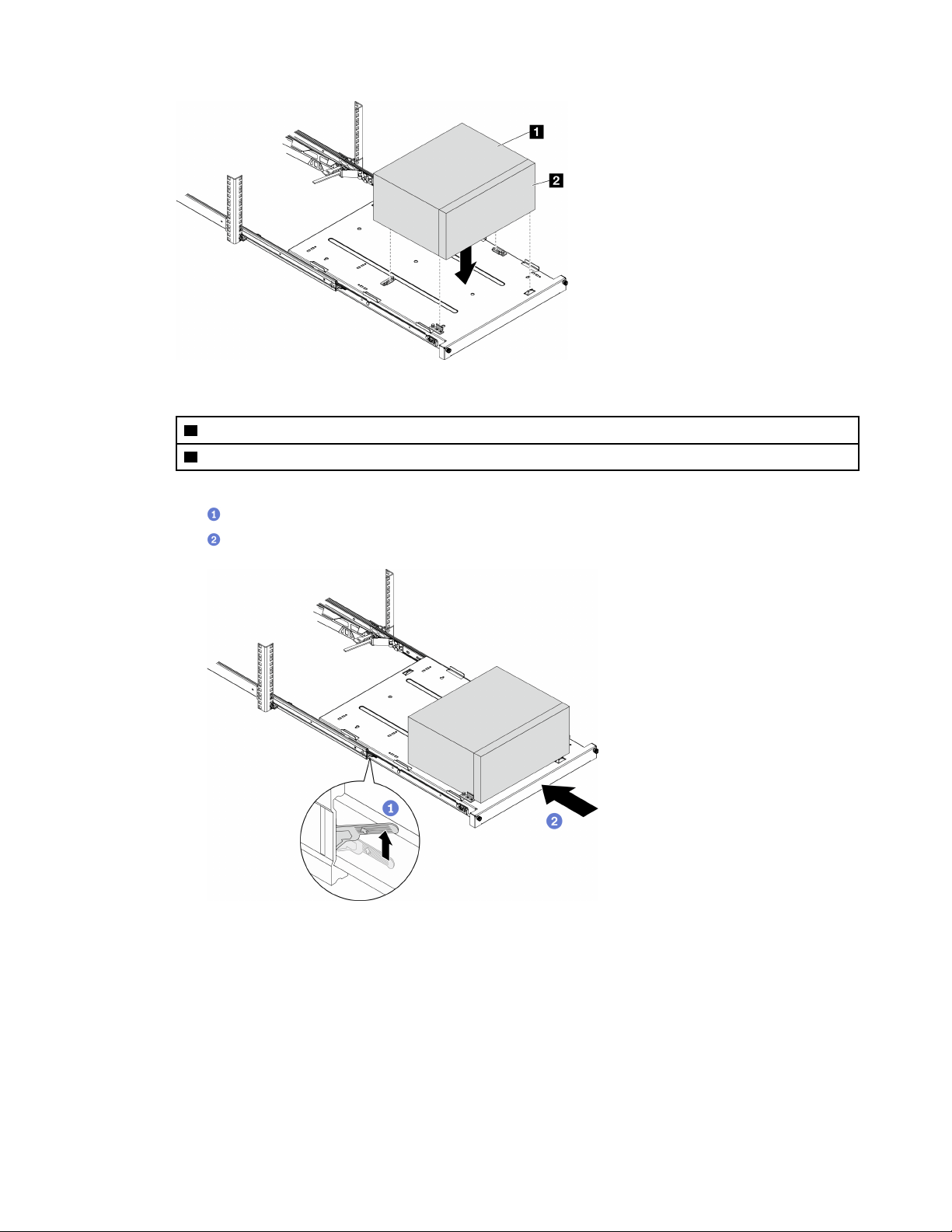
Figure 113. Installing the server to the tray
1 Server cover
2 Server front bezel
Step 4. Install the server into the rack cabinet.
a.
Lift the rail latches on both sides.
b. Gently slide and push the tray into the rack cabinet.
Figure 114. Installing the server into the rack cabinet
Step 5. Secure the tray with two M6 x 16 screws to the front of the rack cabinet.
Chapter 3. Hardware replacement procedures 143
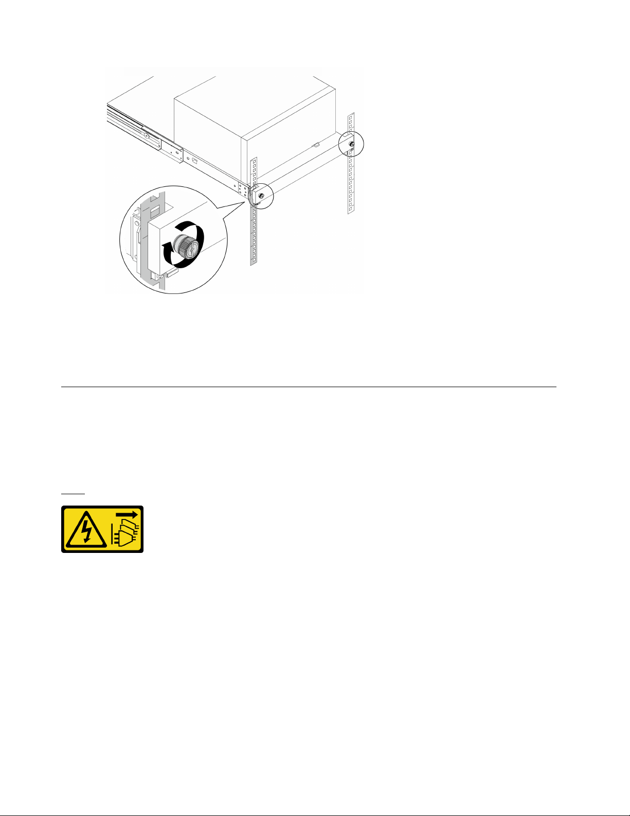
Figure 115. Securing the tray with screws
After you finish
Proceed to complete the parts replacement, see
“Complete the parts replacement” on page 158.
Server cover replacement
Follow this procedure to remove and install the server cover.
Remove the server cover
Follow this procedure to remove the server cover.
S002
CAUTION:
The power-control button on the device and the power switch on the power supply do not turn off the
electrical current supplied to the device. The device also might have more than one power cord. To
remove all electrical current from the device, ensure that all power cords are disconnected from the
power source.
144
ThinkSystem ST50 V2 Maintenance Manual
S014
CAUTION:
Hazardous voltage, current, and energy levels might be present. Only a qualified service technician is
authorized to remove the covers where the label is attached.
S033
CAUTION:
Hazardous energy present. Voltages with hazardous energy might cause heating when shorted with
metal, which might result in spattered metal, burns, or both.
About this task
Attention:
• Read
“Safety inspection checklist” on page iv and “Installation guidelines” on page 41 to ensure that you
work safely.
• Turn off the server and peripheral devices, and disconnect the power cords and all external cables, see
“Power off the server” on page 9.
• If the server is in a rack, remove it from the rack. See
“Remove the server from the rails” on page 138.
• Remove any locking device that secures the server, such as a Kensington lock or a padlock.
• Place the server on its side with the cover up.
Watch the procedure
A video of this procedure is available at YouTube:
https://www.youtube.com/playlist?list=PLYV5R7hVcs-
AU3iY3F7lq3qfqr5caGbIu
.
Procedure
Step 1. Place the server on its side with the cover up.
Step 2. Remove the serve cover.
a.
Use a screwdriver to remove the two screws that secure the server cover to the chassis.
b.
Slide the server cover away from the front bezel, and lift it up from the chassis. Reserve the
screws to be used for reinstalling the server cover.
Attention:
• The heat sinks and processor could be very hot. To avoid burning yourself, wait for a few
minutes after turning off the server before you remove the server cover.
• For proper cooling, always install the server cover before powering on the server. Operating
the server without the cover properly installed might result in server component damage.
Chapter 3. Hardware replacement procedures 145
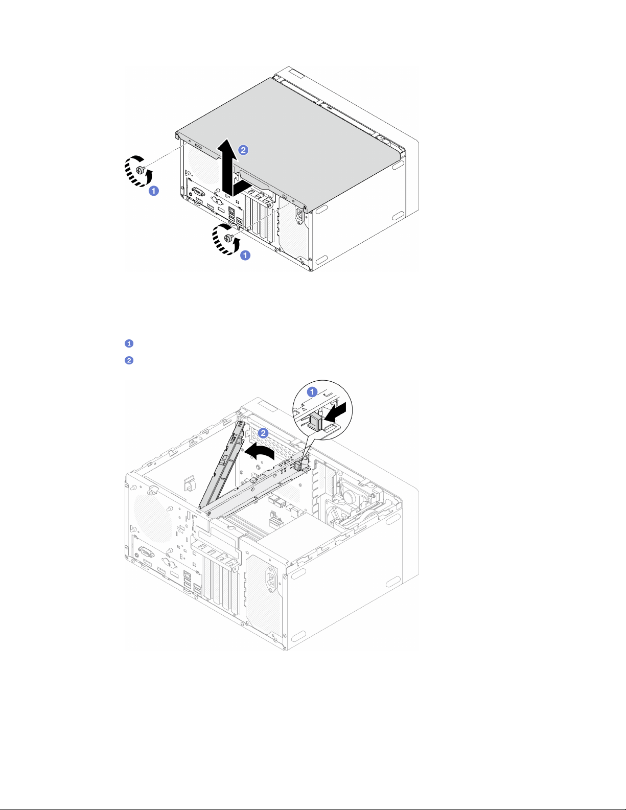
Figure 116. Removing the serve cover
Step 3. (Optional) Remove the cage bar. Remove the optical drive cage first, see
“Remove the optical
drive cage” on page 76
; then, proceed to the following procedures.
a.
Push the latch on the cage bar until the cage bar is disengaged from the chassis.
b.
Rotate the cage bar and remove it from the chassis.
Figure 117. Removing the cage bar
After you finish
If you are instructed to return the component or optional device, follow all packaging instructions, and use
any packaging materials for shipping that are supplied to you.
146 ThinkSystem ST50 V2 Maintenance Manual
Install the server cover
Follow this procedure to install the server cover.
S002
CAUTION:
The power-control button on the device and the power switch on the power supply do not turn off the
electrical current supplied to the device. The device also might have more than one power cord. To
remove all electrical current from the device, ensure that all power cords are disconnected from the
power source.
S014
CAUTION:
Hazardous voltage, current, and energy levels might be present. Only a qualified service technician is
authorized to remove the covers where the label is attached.
S033
CAUTION:
Hazardous energy present. Voltages with hazardous energy might cause heating when shorted with
metal, which might result in spattered metal, burns, or both.
About this task
Attention:
• Read
“Safety inspection checklist” on page iv and “Installation guidelines” on page 41 to ensure that you
work safely.
• Ensure that all adapters and other components are installed and seated correctly, and that you have not
left loose tools or parts inside the server.
• Ensure that all internal cables are correctly routed, see
“Internal cable routing” on page 19 for more
information.
• If you are installing a new server cover, attach the service label to the inside of the new server cover if
necessary.
Note: A new server cover comes without a service label attached. If you need a service label, order it
together with the new server cover. The service label is free of charge.
Watch the procedure
Chapter 3. Hardware replacement procedures 147
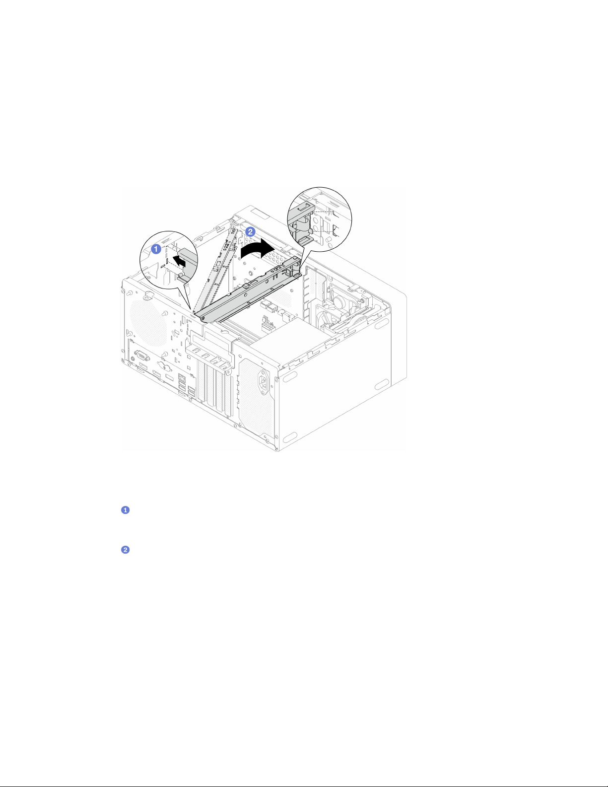
A video of this procedure is available at YouTube: https://www.youtube.com/playlist?list=PLYV5R7hVcs-
AU3iY3F7lq3qfqr5caGbIu
.
Procedure
Step 1. (Optional) Install the cage bar.
a. Insert the tabs on cage bar to the slots on the rear side of the chassis.
b. Align the tabs on the other end of the cage bar to the slots on the front side of the chassis, and
rotate the cage bar toward the front of the chassis until the cage bar is secured in place.
Figure 118. Installing the cage bar
Step 2. Install the serve cover.
a.
Align the server cover to the slots on the side of the chassis. Ensure that all the tabs on the
cover align are engaged with chassis properly; then, slide the cover towards the front bezel
until it snaps in place.
b.
Use a screwdriver to fasten the two screws to secure the cover to the chassis.
148
ThinkSystem ST50 V2 Maintenance Manual
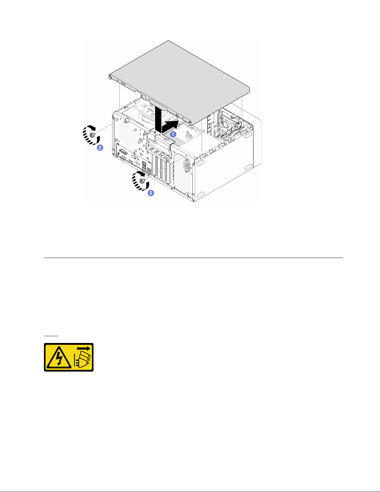
Figure 119. Installing the server cover
After you finish
Proceed to complete the parts replacement, see “Complete the parts replacement” on page 158.
System board replacement (trained technician only)
Follow this procedure to remove and install the system board. This procedure must be executed by a trained
technician.
Remove the system board (trained technician only)
Follow this procedure to remove the system board. This procedure must be executed by a trained
technician.
S002
CAUTION:
The power-control button on the device and the power switch on the power supply do not turn off the
electrical current supplied to the device. The device also might have more than one power cord. To
remove all electrical current from the device, ensure that all power cords are disconnected from the
power source.
About this task
Chapter 3. Hardware replacement procedures 149

Important: Record all the settings in the Setup Utility, as you might have to re-enter these settings after
replacing the system board.
Attention:
• Read
“Safety inspection checklist” on page iv and “Installation guidelines” on page 41 to ensure that you
work safely.
• Turn off the server and peripheral devices, and disconnect the power cords and all external cables, see
“Power off the server” on page 9.
• If the server is in a rack, remove it from the rack. See
“Remove the server from the rails” on page 138.
• Remove any locking device that secures the server, such as a Kensington lock or a padlock.
• Place the server on its side with the cover up.
Watch the procedure
A video of this procedure is available at YouTube:
https://www.youtube.com/playlist?list=PLYV5R7hVcs-
AU3iY3F7lq3qfqr5caGbIu
.
Procedure
Step 1. Make preparation for this task.
a. Remove the server cover, see
“Remove the server cover” on page 144.
Note: The heat sink and processor could be very hot. To avoid burning yourself, wait for a few
minutes after turning off the server before you remove the server cover.
b. If applicable, remove the intrusion switch, see
“Remove the intrusion switch” on page 100.
c. Remove the front bezel, see
“Remove the front bezel” on page 84.
d. If applicable, remove the optical drive, see
“Remove an optical drive” on page 70.
e. If applicable, remove the optical drive cage, see
“Remove the optical drive cage” on page 76.
f. If applicable, remove the cage bar, see Step 3 in
“Remove the server cover” on page 144.
g. If necessary, remove the rear fan, see
“Remove the fan (front and rear)” on page 80.
h. If necessary, remove the M.2 drive, see
“Remove an M.2 drive” on page 104.
i. If necessary, remove the PCIe adapters, see
“Remove a PCIe adapter” on page 120.
j. Remove the front panel, see
“Remove the front panel” on page 87.
k. Remove all memory modules, see
“Remove a memory module” on page 112.
l. Remove the heat sink and fan module, see
“Remove the heat sink and fan module (trained
technician only)” on page 93
.
m. Remove the processor, see
“Remove the processor (trained technician only)” on page 134.
Step 2. Disconnect all the cables connected to the system board.
Attention: Disengage all latches, cable clips, release tabs, or locks on cable connectors
beforehand. Failing to release them before removing the cables will damage the cable connectors
on the system board. Any damage to the cable connectors may require system board replacement.
Step 3. Remove the nine screws that secure the system board in the sequence shown on the illustration
below. Keep the screws for future use.
150
ThinkSystem ST50 V2 Maintenance Manual
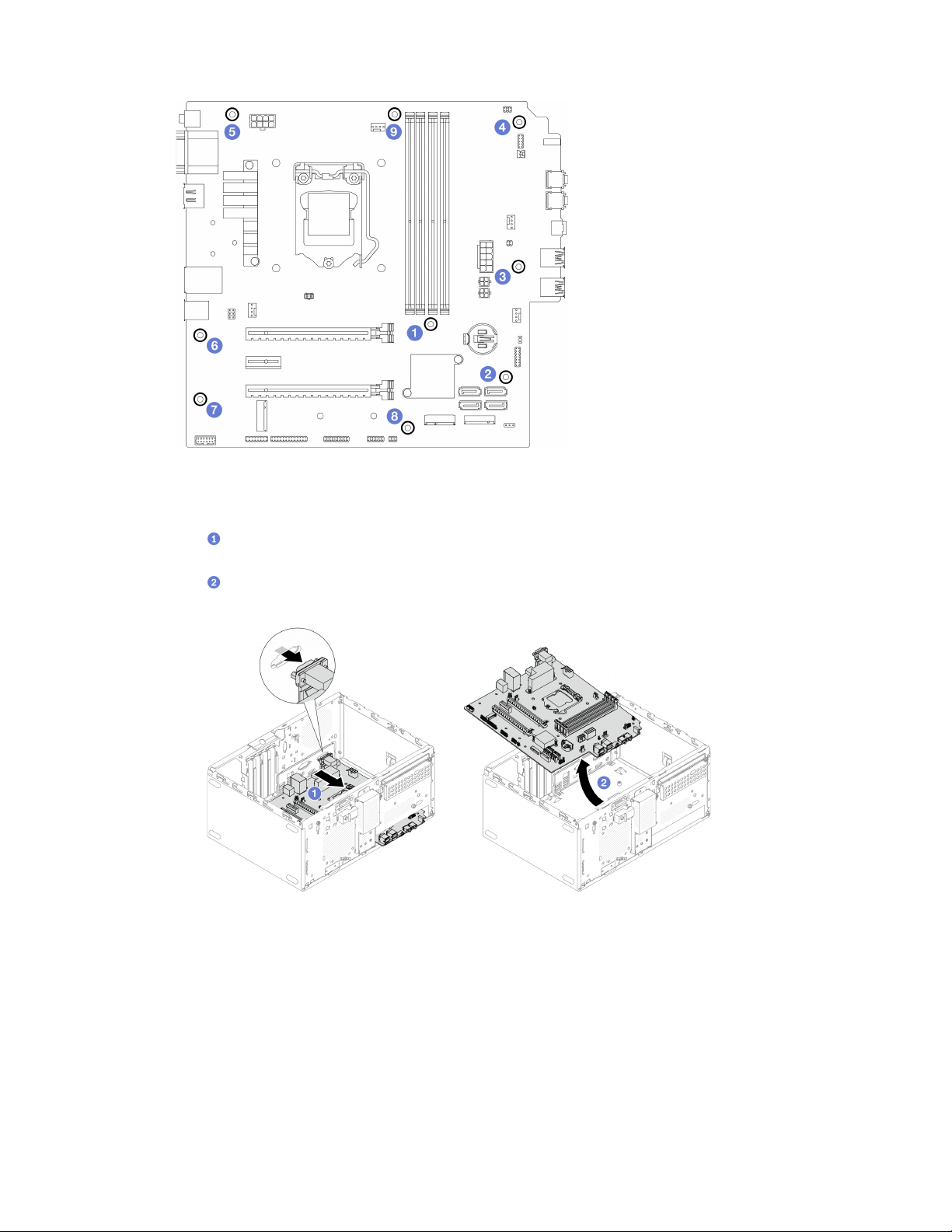
Figure 120. System-board screws removal sequence
Step 4. Remove the system board from the chassis.
a.
Slide the system board toward the front of the server to release the serial port connector
from the chassis.
b.
Gently grasp the system board by the edges; then, tilt the system board, and remove it from
the chassis.
Figure 121. Removing the system board from the chassis
After you finish
1. Install a new system board, see
“Install the system board (trained technician only)” on page 151.
2. If you are instructed to return the component or optional device, follow all packaging instructions, and
use any packaging materials for shipping that are supplied to you.
Install the system board (trained technician only)
Follow this procedure to install the system board. This procedure must be executed by a trained technician.
Chapter 3. Hardware replacement procedures 151
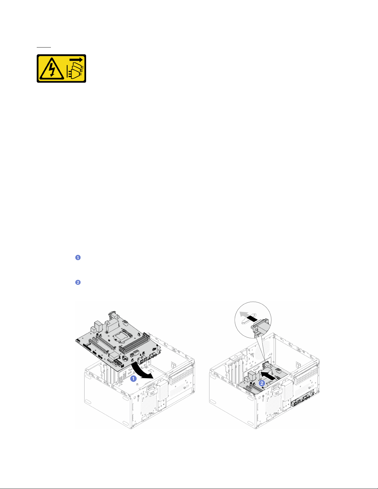
S002
CAUTION:
The power-control button on the device and the power switch on the power supply do not turn off the
electrical current supplied to the device. The device also might have more than one power cord. To
remove all electrical current from the device, ensure that all power cords are disconnected from the
power source.
About this task
Attention:
• Read
“Safety inspection checklist” on page iv and “Installation guidelines” on page 41 to ensure that you
work safely.
• Touch the static-protective package that contains the component to any unpainted metal surface on the
server; then, remove it from the package and place it on a static-protective surface.
Watch the procedure
A video of this procedure is available at YouTube:
https://www.youtube.com/playlist?list=PLYV5R7hVcs-
AU3iY3F7lq3qfqr5caGbIu
.
Procedure
Step 1. Install the system board.
a.
Tilt the system board, and align the connectors with the corresponding opening on the front
of the chassis. Then, gently lower the system board into the chassis, and insert the connectors
into the slot on the front of the chassis.
b.
Slide the system board toward the rear of the chassis until the system board is secured in
place.
Figure 122. Installing the system board into the chassis
152 ThinkSystem ST50 V2 Maintenance Manual
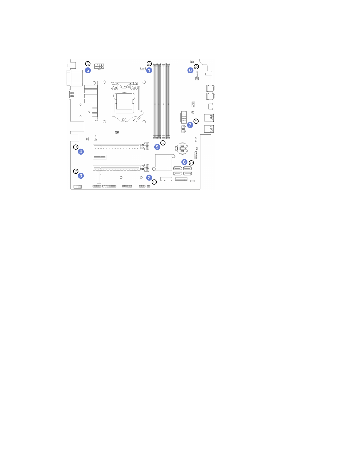
Step 2. Secure the system board to the chassis with nine screws in the sequence shown on the illustration
below.
Figure 123. System-board screws installation sequence
After you finish
Note: Make sure the CMOS battery is installed on the system board, see
“Install the CMOS battery
(CR2032)” on page 47
.
1. Reinstall the processor. see
“Install the processor (trained technician only)” on page 136.
2. Reinstall the heat sink and fan module, see
“Install the heat sink and the fan module (trained technician
only)” on page 97
3. Reinstall the memory modules. see “Install a memory module” on page 113.
4. Reinstall the front panel, see
“Install the front panel” on page 91.
5. If necessary, reinstall the PCIe adapters, see
“Remove a PCIe adapter” on page 120.
6. If necessary, reinstalled the M.2 drive, see
“Install an M.2 drive” on page 106.
7. If applicable, reinstall the rear fan, see
“Install the fan (front and rear)” on page 82.
8. If applicable, reinstall the cage bar, see Step 1 in
“Install the server cover” on page 147.
9. If necessary, reinstall the optical drive cage, see
“Install the optical drive cage” on page 78.
10. If necessary, reinstall the optical drive, see “Install an optical drive” on page 73.
11. Reinstall the front bezel, see
“Install the front bezel” on page 86.
12. Reconnect all the cables that were disconnected.
13. Complete the parts replacement, see
“Complete the parts replacement” on page 158.
14. Update UEFI BIOS, VPD, and security locked procedures. See
https://datacentersupport.lenovo.com/
solutions/HT513859
(Not including PRC) or https://datacentersupport.lenovo.com/solutions/HT513863
(PRC only).
15. Important Update the system firmware and device driver.
• Go to
https://datacentersupport.lenovo.com/tw/en/products/servers/thinksystem/st50v2/downloads/
driver-list/
to see the latest firmware and driver updates for your server.
Chapter 3. Hardware replacement procedures 153

• Go to “Update the firmware” on page 8 for more information on firmware updating tools.
Thermal sensor replacement
Follow this procedure to remove and install the thermal sensor.
Remove the thermal sensor
Follow this procedure to remove the thermal sensor.
S002
CAUTION:
The power-control button on the device and the power switch on the power supply do not turn off the
electrical current supplied to the device. The device also might have more than one power cord. To
remove all electrical current from the device, ensure that all power cords are disconnected from the
power source.
About this task
Attention:
• Read
“Safety inspection checklist” on page iv and “Installation guidelines” on page 41 to ensure that you
work safely.
• Turn off the server and peripheral devices, and disconnect the power cords and all external cables, see
“Power off the server” on page 9.
• If the server is in a rack, remove it from the rack. See
“Remove the server from the rails” on page 138.
• Remove any locking device that secures the server, such as a Kensington lock or a padlock.
• Place the server on its side with the cover up.
Watch the procedure
A video of this procedure is available at YouTube:
https://www.youtube.com/playlist?list=PLYV5R7hVcs-
AU3iY3F7lq3qfqr5caGbIu
.
Procedure
Step 1. Make preparation for this task.
a. Remove the server cover, see
“Remove the server cover” on page 144.
Note: The heat sink and processor could be very hot. To avoid burning yourself, wait for a few
minutes after turning off the server before you remove the server cover.
b. Remove the front bezel, see
“Remove the front bezel” on page 84.
c. Remove the front fan, see
“Remove the fan (front and rear)” on page 80.
d. If applicable, remove the M.2 drive, see
“Remove an M.2 drive” on page 104.
Step 2. Disconnect the thermal sensor cable from the system board.
154
ThinkSystem ST50 V2 Maintenance Manual
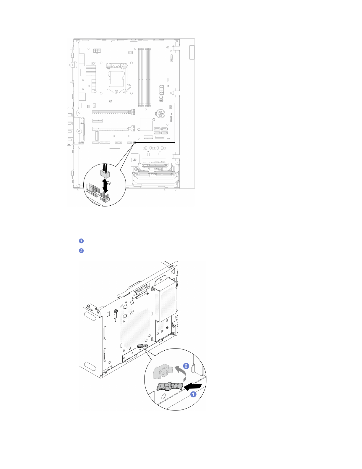
After you finish
1. Install a new thermal sensor, see
“Install the thermal sensor” on page 156.
2. If you are instructed to return the component or optional device, follow all packaging instructions, and
use any packaging materials for shipping that are supplied to you.
Install the thermal sensor
Follow this procedure to install the thermal sensor.
S002
CAUTION:
The power-control button on the device and the power switch on the power supply do not turn off the
electrical current supplied to the device. The device also might have more than one power cord. To
remove all electrical current from the device, ensure that all power cords are disconnected from the
power source.
About this task
Attention:
1. Read
“Safety inspection checklist” on page iv and “Installation guidelines” on page 41 to ensure that you
work safely.
2. Touch the static-protective package that contains the component to any unpainted metal surface on the
server; then, remove it from the package and place it on a static-protective surface.
Watch the procedure
A video of this procedure is available at YouTube:
https://www.youtube.com/playlist?list=PLYV5R7hVcs-
AU3iY3F7lq3qfqr5caGbIu
.
Procedure
Step 1. Install the thermal sensor.
a.
From the inside of the chassis, attach the end of the thermal sensor to the corresponding
slot on the front of the chassis.
b.
From inside of the chassis, push the thermal sensor into the slot.
c.
Make sure the thermal sensor is secured in place.
156
ThinkSystem ST50 V2 Maintenance Manual
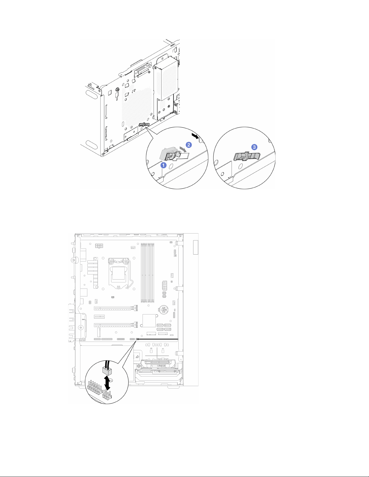

1. If an M.2 drive was removed, reinstall the M.2 drive, see “Install an M.2 drive” on page 106.
Note: The thermal sensor cable should be placed under the M.2 drive.
2. Reinstall the front fan, see
“Install the fan (front and rear)” on page 82.
3. Reinstall the front bezel, see
“Install the front bezel” on page 86.
4. Proceed to complete the parts replacement, see
“Complete the parts replacement” on page 158.
Complete the parts replacement
To complete the parts replacement, do the following:
1. Ensure that all the removed components have been reinstalled correctly and that no tools or loose
screws are left inside the server.
2. Ensure that the CMOS battery is installed on the system board, see
“Install the CMOS battery (CR2032)”
on page 47
.
3. Properly route and secure the cables in the server. Refer to the cable connecting and routing information
for each component.
4. Reinstall the server cover, see
“Install the server cover” on page 147.
5. If the server was removed from the rack previously, put it back into the rack, see
“Install the server to the
rails” on page 140
.
6. Reconnect external cables and power cords to the server.
Attention: To avoid component damage, connect all the other cables before connecting the power
cords.
7. Update the server configuration if necessary.
• Go to
https://datacentersupport.lenovo.com/tw/en/products/servers/thinksystem/st50v2/downloads/
driver-list/
to see the latest firmware and driver updates for your server.
• Go to
“Update the firmware” on page 8 for more information on firmware updating tools.
158
ThinkSystem ST50 V2 Maintenance Manual

Chapter 4. Problem determination
Use the information in this section to isolate and resolve issues that you might encounter while using your
server.
Event logs
Logs of system events are available in Setup Utility.
Setup Utility provides the list of system event log that is available in the security tab. Start the server and
press F1 to access Setup Utility, and go to Security ➙ System Event Log ➙ View System Event Log to
access the list of events.
Following is the list of events that might appear in the system event log.
Table 30. List of log events in Setup Utility
Event description
Setup data integrity check failure
Memory size decreased
Fan failure
Power supply overload
BIOS password changed
BIOS Setup data changed
Chassis intrusion
Password retry count exceeded
SATA device configuration changed
BIOS updated
Option ROM over Shadow RAM size
Hard disk password changed
PCI Mem Conflict
System event log cleared
General problem determination procedures
Use the information in this section to resolve problems if the event log does not contain specific errors or the
server is inoperative.
If you are not sure about the cause of a problem and the power supplies are working correctly, complete the
following steps to try to resolve the problem:
1. Check in Setup Utility and make sure all the installed components are enabled.
2. Make sure the firmware of the installed components are the latest version.
3. Turn off the server.
4. Ensure that the server is cabled correctly.
© Copyright Lenovo 2022, 2022 159
5. Remove or disconnect the following devices if applicable, one at a time, until you find the failure. Turn on
and configure the server each time you remove or disconnect a device.
• Any external devices
• Surge-suppressor device (on the server)
• Printer, mouse, and non-Lenovo devices
• Each adapter
• Storage drives
• One memory module at a time until you reach the minimum configuration that is supported for the
server
Notes: The minimum configuration required for the server is as the following:
• One processor
• One 8 GB ECC UDIMM in slot 1
• One power supply
• One 3.5-inch drive in drive bay 1
• Power cord
• One system front fan
6. Turn on the server.
7. Listen to the POST error beeps.
Table 31. POST error beeps
Beep Error description
Three short ones followed by one long one No memory is detected by the system.
Two long one followed by three short ones No video card (including intergrated video card) is detected by the
system.
Note: A short beep lasts about 0.4 second, while a long one lasts about 0.9 second.
If the problem is solved after an adapter is removed from the server, but recurs after it is reinstalled, suspect
the adapter. If the problem recurs when the adapter is replaced with a different one, try the original adapter in
a different PCIe slot.
If the problem appears to be a networking one while the server passes all system diagnostics, suspect a
network cabling problem that is external to the server.
List of POST error messages
See this section for the list of POST error and related information.
00CE - Machine Type or Serial Number is INVALID
Machine type or serial number invalid.
This error message will be displayed if one of the following conditions is true:
1. Machine type and model name is invalid.
2. System serial number is invalid.
To update these product information, go to
http://datacentersupport.lenovo.com/us/en/products/servers/
thinksystem/st50v2/downloads
and download the “The uEFI VPD SMBIOS Information Update Utility”.
0135 - Fan Failure
Fan related failures.
160
ThinkSystem ST50 V2 Maintenance Manual

This error message will be displayed if one of the following malfunctions occurs:
1. Heat sink fan failure
2. Front fan failure (Aux fan failure)
The front fan is shown as Aux Fan in BIOS Setup Utility. To see the Aux Fan, go to Setup Utility, select
Main ➙ System Summary ➙ Aux Fan
3. Rear fan failure (System fan)
The rear fan is shown as System Fan in BIOS Setup Utility. To see the System Fan, go to Setup Utility,
select Main ➙ System Summary ➙ System Fan
0164 - Memory Size Change or memory module installed slot change
Memory size change or memory module installed slot change is detected.
When Configuration Change Detection is enabled, this error message will be displayed when the memory
size increased/decreased, or when a memory module was moved from one slot to another.
To clear this error from the list of POST events, go to Setup Utility and select Save Changes and Exit.
1762 - Storage Device Configuration Change Has Occurred
Storage configuration (SATA devices and M.2 device) has been changed.
When Configuration Change Detection is enabled, this error message will be displayed when there is any
configuration change related to SATA drives (including optical drive) and M.2 drive.
Notes:
1. Change the drive SATA connectors will cause this error.
2. The M.2 drive detected is limited to the M.2 drive connected to the system-board M.2 slots.
3. To clear this error from the list of POST events, go to Setup Utility and select Save Changes and Exit.
0162 - Setup data integrity check failure
This error message indicates the checksum of BIOS Setup data in NVRAM is bad.
To clear this error from the list of POST events, go to Setup Utility and select Save Changes and Exit.
0167 - No Processor Microcode Update Found
This error message indicates that there is no microcode update image exists for the current processor.
0175 - System Security - Security data corrupted
This error message indicates the stored security data is corrupted.
To clear this error from the list of POST events, go to Setup Utility and select Save Changes and Exit.
0176 - System Security - The system has been tampered with
The system has been tampered with.
When Chassis Intrusion Function is enabled, this error will be displayed when the cover is not properly
installed before the server is powered on.
To clear this error from the list of POST events, go to Setup Utility and select Save Changes and Exit.
0189 - System Security - Cannot read the Security EEPROM
The Security EEPROM cannot be accessed.
Chapter 4. Problem determination 161

During POST, a read/write test is performed to verify access to the Security EEPROM. This error message
indicates that the Security EEPROM may be corrupted or removed.
To clear this error from the list of POST events, go to Setup Utility and select Save Changes and Exit.
0197 - System Security - Unauthorized security data change detected
There is unauthorized security data change.
During POST, the hash of current security data is computed and compared with the one kept in security
EEPROM. If they are not the same, this error will be displayed.
To clear this error from the list of POST events, go to Setup Utility and select Save Changes and Exit.
0190 - System Security - Invalid security change requested
An invalid request of security change is received.
During POST, CRC of the data stored in security EEPROM block 7 is computed and compared with the one
kept in the block 7. If they do not match, this error will be displayed.
To clear this error from the list of POST events, go to Setup Utility and select Save Changes and Exit.
0199 - System Security - Security password retry count exceeded on last boot
Wrong passwords are inputted for more than the number of times that is allowed.
When Security Password Count Exceeded Error is enabled, this error will be displayed after wrong
passwords are inputted over maximal number of times. Select F2 to resume and input the correct password.
To clear this error from the list of POST events, go to Setup Utility and select Save Changes and Exit.
8997 - System firmware has detected the system configuration may exceed the
power supply capacity
The required amount of power of the present system configuration is more than the power supply could
afford.
This error will be displayed when the system algorithm determines that present power consumption exceeds
the capacity of the installed power supply unit. This error message is supposed to be displayed for at least
five seconds and follow by another boot.
8998 - No enough shadow RAM resources for option ROM
Not enough shadow RAM resources for option ROM. Not all devices are initialized. Please remove some
add-on cards or change to UEFI mode in BIOS Setup Utility.
This error message indicates some devices are not properly initiated. Remove them or change the settings in
Setup Utility. It will be displayed for at least five seconds with four one-second beeps before the next boot.
8999 - No enough PCIe/PCI MMIO resources
Not enough PCIe/PCI MMIO resources. Currently only one video card is enabled. Please remove some PCIe
cards, or enter BIOS Setup Utility and enable “Above 4GB Decode” if using a 64-bit OS.
This error will be displayed when there is no enough PCIe/PCI MMIO resources following a reboot and with
the attempt to initialize the primary video device to display this error message. This error will be displayed for
at least five seconds with four one-second beeps before the next boot. Remove some PCIe adapters in
Setup Utility to solve this error.
162
ThinkSystem ST50 V2 Maintenance Manual

Resolving suspected power problems
Power problems can be difficult to solve. For example, a short circuit can exist anywhere on any of the power
distribution buses. Usually, a short circuit will cause the power subsystem to shut down because of an
overcurrent condition.
Complete the following steps to diagnose and resolve a suspected power problem.
Step 1. Check for short circuits, for example, if a loose screw causes short circuit on a circuit board.
Step 2. Remove the adapters and disconnect the cables and power cords to all internal and external
devices until the server is at the minimum configuration that is required for the server to start. The
minimum configuration required for the server is as the following:
• One processor
• One 8 GB ECC UDIMM in slot 1
• One power supply
• One 3.5-inch drive in drive bay 1
• Power cord
• One system front fan
Step 3. Reconnect all AC power cords and turn on the server. If the server starts successfully, reseat the
adapters and devices one at a time until the problem is isolated.
If the server does not start from the minimum configuration, replace the components in the minimum
configuration one at a time until the problem is isolated.
Resolving suspected Ethernet controller problems
The method that you use to test the Ethernet controller depends on which operating system you are using.
See the operating-system documentation for information about Ethernet controllers, and see the Ethernet
controller device-driver readme file.
Complete the following steps to try to resolve suspected problems with the Ethernet controller.
Step 1. Make sure that the correct device drivers which come with the server are installed, and that they
are at the latest level.
Step 2. Make sure that the Ethernet cable is installed correctly.
• The cable must be securely attached at all connections. If the cable is attached but the problem
remains, try a different cable.
• If you set the Ethernet controller to operate at 100 Mbps or 1000 Mbps, you must use Category
5 cabling.
Step 3. Determine whether the hub supports auto-negotiation. If it does not, try configuring the integrated
Ethernet controller manually to match the speed and duplex mode of the hub.
Step 4. Check the Ethernet controller LEDs on the rear panel of the server. These LEDs indicate whether
there is a problem with the connector, cable, or hub.
• The Ethernet link status LED is lit when the Ethernet controller receives a link pulse from the hub.
If the LED is off, there might be a defective connector or cable or a problem with the hub.
• The Ethernet transmit/receive activity LED is lit when the Ethernet controller sends or receives
data over the Ethernet network. If the Ethernet transmit/receive activity is off, make sure that the
hub and network are operating and that the correct device drivers are installed.
Step 5. Check for operating-system-specific causes of the problem, and also make sure that the operating
system drivers are installed correctly.
Step 6. Make sure that the device drivers on the client and server are using the same protocol.
Chapter 4. Problem determination 163

If the Ethernet controller still cannot connect to the network, but the hardware appears to be working, the
network administrator must investigate other possible causes of the error.
Troubleshooting by symptom
Follow this procedure to find solutions to problems that have identifiable symptoms.
To use the symptom-based troubleshooting information in this section, complete the following steps:
1. Review this section to find the symptoms that you are experiencing, and follow the suggested actions to
resolve the issue.
2. If the problem persists, contact support (see
“Contacting Support” on page 178).
Power on and power off problems
Follow this procedure to resolve issues when powering on or powering off the server.
•
“Embedded hypervisor is not in the boot list” on page 164
• “The server does not power on” on page 164
• “Server powers off unexpectedly” on page 165
• “Server does not power off” on page 165
Embedded hypervisor is not in the boot list
Complete the following steps until the problem is solved.
1. If the server has been installed, moved, or serviced recently, or if this is the first time the embedded
hypervisor is being used, make sure that the device is connected properly and that there is no physical
damage to the connectors.
2. See the documentation that comes with the optional embedded hypervisor device for setup and
configuration information.
3. Make sure that software that is installed in the device works on another server to ensure that the device
works properly.
4. Check
https://static.lenovo.com/us/en/serverproven/index.shtml to validate that the embedded hypervisor
device is supported by the server.
5. Make sure that the embedded hypervisor device is included in the list of available boot options. To view
the list of boot sequences, go to Setup Utility, select Startup ➙ Boot Priority Order.
6. Check
http://datacentersupport.lenovo.com for any tech tips (service bulletins) related to the embedded
hypervisor and the server.
The server does not power on
Complete the following steps until the problem is solved.
Note: The power button will not function until approximately one to three minutes after the server is
connected to ac power.
1. Remove any optional devices that were installed recently. System power problems caused by addition
of a device indicates this device is either incompatible or too much for the power supply to support.
2. Make sure the power cord is securely connected to the server and to a working electrical outlet.
Disconnect and reconnect or replace the server power cord.
3. Remove and reinstall the power supply. If the problem persists, replace the power supply.
164
ThinkSystem ST50 V2 Maintenance Manual

4. Disconnect and reconnect the front panel cable (see “System board components” on page 18 for the
location of the connector on the system board). If the problem persists, replace the front panel.
Server powers off unexpectedly
Complete the following steps until the problem is solved.
1. Make sure the room temperature does not cause overheating, and no object is blocking the airflow in
front and back of the server.
2. Remove any optional devices that were installed recently. System power problems caused by addition
of a device indicates this device is either incompatible or too much for the power supply to support.
3. Make sure the power cord is securely connected to the server and to a working electrical outlet.
Disconnect and reconnect or replace the server power cord.
4. Reseat the power supply. If the problem persists, replace the power supply.
Server does not power off
Complete the following steps until the problem is solved.
1. Determine whether you are using an Advanced Configuration and Power Interface (ACPI) or a non-ACPI
operating system. If you are using a non-ACPI operating system, complete the following steps:
a. Press
Ctrl+Alt+Delete.
b. Turn off the server by pressing and holding the power button for five seconds.
c. Power on the server.
d. If the server fails POST and the power button does not work, disconnect the power cord for 20
seconds; then, reconnect the power cord and power on the server.
2. If the problem persists or if you are using an ACPI-aware operating system, suspect the system board.
Memory problems
Follow this procedure to resolve issues related to memory.
•
“Displayed system memory less than installed physical memory” on page 165
Displayed system memory less than installed physical memory
Note: Each time you install or remove a DIMM, you must disconnect the server from the power source; then,
wait 10 seconds before restarting the server.
Complete the following steps until the problem is solved.
1. Check the system event log and resolve any related problems. To view the system event log, go to
Setup Utility and select Security ➙ System Event Log ➙ View System Event Log.
2. Make sure that:
• The DIMMs are supported by the server (see
https://static.lenovo.com/us/en/serverproven/index.shtml).
• The DIMMs are properly installed. Examine if there is any gap between the connector and the DIMM.
Remove and install the DIMM if there is any.
3. If the server comes with Lenovo XClarity Provisioning Manager Lite, go to Diagnostics ➙ Memory test
to perform diagnostics on the DIMMs. Replace the DIMM that is displayed as faulty. Otherwise, skip to
the next step.
Chapter 4. Problem determination 165

4. Remove the DIMMs until the system reaches minimal memory requirement; then, add one DIMM and
reboot the server, and repeat the step if the problem does not recur. If the problem occurs after addition
of a DIMM, replace it.
See “Specifications” on page 2 for the minimal configuration for debugging.
Hard disk drive problems
Follow this procedure to resolve issues related to the hard disk drives.
•
“Server cannot recognize a drive” on page 166
• “Multiple hard drives fail” on page 166
• “A replacement drive does not rebuild” on page 166
• “Suspected RAID volume failure” on page 167
Server cannot recognize a drive
Complete the following steps until the problem is solved.
1. Check the system event log and resolve any related problems. To view the system event log, go to
Setup Utility and select Security ➙ System Event Log ➙ View System Event Log.
2. Make sure that:
• The drive is supported by the server (see
https://static.lenovo.com/us/en/serverproven/index.shtml).
• The drive is properly installed with signal and power cables properly connected.
3. Make sure the drive is enabled. Go to Setup Utility and select Devices ➙ ATA Drive Setup to see if the
drive in question is enabled. If not, enable it.
4. If the server comes with LXPM Lite, go to Diagnostics ➙ HDD test to perform diagnostics on the drives.
Replace the drive that is displayed as faulty. Otherwise, skip to the next step.
5. Remove the drives until the system reaches minimal drive requirement; then, add one drive and restart
the server, and repeat the step if the problem does not recur. If the problem occurs after addition of a
drive, replace it.
See
“Specifications” on page 2 for the minimal configuration for debugging.
Multiple hard drives fail
Complete the following steps until the problem is solved.
1. Check the system event log and resolve any related problems. To view the system event log, go to
Setup Utility and select Security ➙ System Event Log ➙ View System Event Log.
2. If the server comes with Lenovo XClarity Provisioning Manager Lite, go to Diagnostics ➙ HDD test to
perform diagnostics on the drives. Replace the drive that is displayed as faulty. Otherwise, skip to the
next step.
3. Remove the drives until the system reaches minimal drive requirement; then, add one drive and reboot
the server, and repeat the step if the problem does not recur. If the problem occurs after addition of a
drive, replace it.
See
“Specifications” on page 2 for the minimal configuration for debugging.
A replacement drive does not rebuild
Complete the following steps until the problem is solved.
166
ThinkSystem ST50 V2 Maintenance Manual

1. Check the system event log and resolve any related problems. To view the system event log, go to
Setup Utility and select Security ➙ System Event Log ➙ View System Event Log.
2. If the server comes with Lenovo XClarity Provisioning Manager Lite, go to Diagnostics ➙ RAID Log.
Look for related errors and solve them. Otherwise, skip to the next step.
3. Review the document that came with the RAID adapter to make sure RAID is set properly.
Suspected RAID volume failure
The following two symptoms serve as indicator of ThinkSystem RAID adapter virtual driver failure:
• If the virtual driver application is installed in a bootable Operating System drive, the system, unable to
boot, stays in POST screen with message of Warning: No operating system found.
• Otherwise, the drive is missing from disk management options in the operating system.
Complete the following steps until the problem is solved.
1. Reboot the system, press F1 to go to Setup Utility, and select Advanced ➙ x350-8i ➙ Array
Configuration ➙ Manage Arrays ➙ Array X ➙ List Logical Drives ➙ Logical Drive X (Logical Drive
X) ➙ Logical Drive Details to check failure symptoms.
Monitor and video problems
Follow this procedure to solve problems related to a monitor or video.
•
“Incorrect characters are displayed” on page 167
• “Screen is blank” on page 167
• “Screen goes blank when you start some application programs” on page 168
• “The monitor has screen jitter, or the screen image is wavy, unreadable, rolling, or distorted.” on page 168
Incorrect characters are displayed
Complete the following steps until the problem is solved.
1. Verify that the language and locality settings are correct for the keyboard and operating system.
2. If the wrong language is displayed, update the server firmware to the latest level.
Screen is blank
Complete the following steps until the problem is solved.
1. If you have installed new DIMMs recently, make sure the capacity of the new DIMMs are the same as the
previously installed ones. If not, remove the newly installed DIMMs, and power on the server again.
2. If a graphical adapter is installed, wait for a while as it takes about three minutes before Lenovo logo is
displayed.
3. If there are other monitors that are connected to the server, remove them.
4. Make sure that:
• The server is turned on.
• The monitor cables are securely connected.
• The monitor is turned on with brightness and contrast controls adjusted correctly.
5. Disconnect the cable and select another video connector for connection.
6. Replace the following components one at a time, in the order shown, restarting the server each time:
a. Monitor cable
b. Monitor
Chapter 4. Problem determination 167

c. Video adapter (if one is installed)
d. (Trained technician only) System board
Screen goes blank when you start some application programs
Complete the following steps until the problem is solved.
1. Make sure that:
• The application program is not set in a display mode with resolution that is higher than the capability
of the monitor (1920 x 1080).
• The necessary device drivers for the application are all installed.
The monitor has screen jitter, or the screen image is wavy, unreadable, rolling, or distorted.
Complete the following steps until the problem is solved.
1. If the monitor self-tests show that the monitor is working correctly, examine the location of the monitor.
Magnetic fields around other devices (such as transformers, appliances, fluorescent, and other monitors)
can cause screen jitter or wavy, unreadable, rolling, or distorted screen images. If this happens, turn off
the monitor.
Attention: Moving a color monitor while it is turned on might cause screen discoloration.
Move the device and the monitor at least 305 mm (12 inches) apart, and turn on the monitor.
Notes:
a. To prevent diskette drive read/write errors, make sure that the distance between the monitor and any
external diskette drive is at least 76 mm (3 inches).
b. Non-Lenovo monitor cables might cause unpredictable problems.
2. Disconnect and reconnect the monitor cable.
3. Replace the following components one at a time, in the order shown, restarting the server each time:
a. Monitor cable
b. Monitor
c. Video adapter (if one is installed)
d. (Trained technician only) System board
Optional-device problems
Follow this procedure to solve problems related to optional devices.
•
“PCIe adapter is not recognized or is not functioning” on page 168
• “A Lenovo optional device that worked previously does not work now. ” on page 169
• “A Lenovo optional device that was just installed does not work.” on page 169
• “A Lenovo optional device that worked previously does not work now. ” on page 169
PCIe adapter is not recognized or is not functioning
Complete the following steps until the problem is solved.
1. Check the system event log and resolve any related problems. To view the system event log, go to
Setup Utility and select Security ➙ System Event Log ➙ View System Event Log.
2. Make sure that:
• The device is supported by the server (see
https://static.lenovo.com/us/en/serverproven/index.shtml).
• The latest version of corresponding driver is installed.
168
ThinkSystem ST50 V2 Maintenance Manual

• The device is seated correctly without physical damage on the device or connector.
• System firmware has been updated to the latest version.
3. Remove the device and install it to another PCIe slot if possible.
4. Check
http://datacentersupport.lenovo.com for any tech tips (also known as retain tips or service
bulletins) that might be related to the adapter.
Insufficient PCIe resources are detected.
Complete the following steps until the problem is solved.
1. Remove any devices that were installed recently, and restart the server. If none was recently installed,
remove one of the PCIe adapters.
2. Go to Setup Utility and select Devices ➙ PCI Express Configuration; then, modify the setting to a
lower speed. For example, modify the speed of PCIe x16 slot from Auto or Gen4 to Gen3, Gen2, or
Gen1.
3. Save the settings and restart the server.
4. Depending on whether or not the restart is successful:
• If it is successful, shut down the server and reinstall the removed PCIe adapters one at a time, and
restart the server again after each addition.
• If it fails, remove another PCIe adapter and restart the server again.
A Lenovo optional device that was just installed does not work.
Complete the following steps until the problem is solved.
1. Check the system event log and resolve any related problems. To view the system event log, go to
Setup Utility and select Security ➙ System Event Log ➙ View System Event Log.
2. Make sure that:
• The device is supported by the server (see
https://static.lenovo.com/us/en/serverproven/index.shtml).
• The latest version of corresponding driver is installed.
• The device is seated correctly without physical damage on the device or connector.
• System firmware has been updated to the latest version.
• You followed the installation instructions that came with the device, and the device is installed
properly.
• You have not loosened any other installed devices or cables.
3. Reseat the device.
4. Replace the device.
A Lenovo optional device that worked previously does not work now.
Complete the following steps until the problem is solved.
1. Check the system event log and resolve any related problems. To view the system event log, go to
Setup Utility and select Security ➙ System Event Log ➙ View System Event Log.
2. Make sure that all of the cables are securely connected.
3. If the device comes with test instructions, use those instructions to test the device.
4. Reseat the failing device.
5. Replace the failing device.
Intermittent problems
Follow this procedure to solve intermittent problems.
•
“Intermittent external device problems” on page 170
Chapter 4. Problem determination 169

• “Intermittent unexpected reboots” on page 170
Intermittent external device problems
Complete the following steps until the problem is solved.
1. Check the system event log and resolve any related problems. To view the system event log, go to
Setup Utility and select Security ➙ System Event Log ➙ View System Event Log.
2. Make sure that:
• The latest version of corresponding driver is installed.
• The device is seated correctly without physical damage on the device or connector.
• System firmware has been updated to the latest version.
• You followed the installation instructions that came with the device, and the device is installed
properly.
• You have not loosened any other installed devices or cables.
3. For a USB device:
a. Make sure that the device is properly configured and enabled in Setup Utility.
b. Connect the device to another USB port.
c. If the device is connected to a USB hub, remove the device from the hub, and connect it directly to
the server.
Intermittent unexpected reboots
Complete the following steps until the problem is solved.
1. Check the system event log and resolve any issues related to this device. To view the system event log,
go to Setup Utility and select Security ➙ System Event Log ➙ View System Event Log.
2. If the reboot occurs after the operating system starts, disable any automatic server restart (ASR) utilities,
such as the Automatic Server Restart IPMI Application for Windows, or any ASR devices that are
installed.
3. Look into the event logs for an event code that indicates a reboot. See
“Event logs” on page 159 for
information about viewing the event log.
Network problems
Follow this procedure to resolve issues related to networking.
•
“Cannot wake server using Wake on LAN” on page 170
• “Could not log in using LDAP account with SSL enabled” on page 171
Cannot wake server using Wake on LAN
Complete the following steps until the problem is solved.
1. Check the system event log and resolve any related problems. To view the system event log, go to
Setup Utility and select Security ➙ System Event Log ➙ View System Event Log.
2. Change the Wake on LAN setting. Go to Setup Utility and select Power ➙ Automatic Power On ➙
Wake on LAN. The default setting is automatic. Change it to primary.
3. Remove and reinstall the network adapter.
4. Turn off the server and disconnect it from the power source; then, wait 10 seconds before restarting the
server.
5. If the problem recurs, replace the network adapter.
170
ThinkSystem ST50 V2 Maintenance Manual

Could not log in using LDAP account with SSL enabled
Complete the following steps until the problem is solved.
1. Make sure that the license key is valid.
2. Generate a new license key and log in again.
Observable problems
Follow this procedure to solve observable problems.
• “The server immediately displays the POST Event Viewer when it is turned on” on page 171
• “Server is unresponsive (POST is complete and operating system is running)” on page 171
• “Server is unresponsive (cannot press F1 to start Setup Utility)” on page 172
• “Voltage planar fault is displayed in the event log” on page 172
• “Unusual smell” on page 172
• “Server seems to be running hot” on page 172
• “Cracked parts or cracked chassis” on page 172
The server immediately displays the POST Event Viewer when it is turned on
Complete the following steps until the problem is solved.
1. Make sure that the server supports the processor.
To view processor details, go to Setup Utility and select Main ➙ System Summary.
To determine if the processor is supported for the server, see
https://static.lenovo.com/us/en/
serverproven/index.shtml
.
2. (Trained technician only) Make sure that the processor is installed properly.
3. Replace the following components one at a time, in the order shown, and restart the server after each
replacement.
a. (Trained technician only) processor
b. (Trained technician only) system board
Server is unresponsive (POST is complete and operating system is running)
Complete the following steps until the problem is solved.
• If you have direct access to the server, complete the following steps:
1. If possible, log in to the system and verify that all applications are running without hanging.
2. Restart the server.
3. If the problem recurs, make sure that every newly installed software is configured correctly.
4. Contact the vendor or provider of the software for technical support.
• If you have remote access to the server, complete the following steps:
1. If possible, log in to the system and verify that all applications are running without hanging.
2. Log out of the system and log back in.
3. Validate the network access by pinging or running traceroute to the server with a command line.
a. If you are unable to get a response during a ping test, try to ping another server in the same server
room to determine whether the problem is caused by failed connection of the server.
Chapter 4. Problem determination 171

b. Run traceroute to determine where the connection breaks down, and try to resolve the connection
issue with VPN or avoiding where the connection breaks down.
4. Restart the server remotely.
5. If the problem recurs, make sure that every installed software is configured correctly.
6. Contact the vendor or provider of the software for technical support.
Server is unresponsive (cannot press F1 to start Setup Utility)
Complete the following steps until the problem is solved.
Note: Any configuration changes, such as system firmware update, device and corresponding driver
installation, could cause failed POST.
If this occurs, the server responds in either of the following ways:
• The system restarts automatically and produces POST again.
• The server hangs, and you must manually reboot the system so that the system produces POST again.
Voltage planar fault is displayed in the event log
Complete the following steps until the problem is solved.
1. Revert the system to the minimum configuration. See
“Specifications” on page 2 for details.
2. Restart the server.
• If the system does restart successfully, add the devices that are removed one at a time, and restart
the server after each addition until the problem occurs. Replace the device that causes the problem.
• If the system fails to restart, there might be a problem with the system board. Call Lenovo support.
Unusual smell
Complete the following steps until the problem is solved.
1. Any unusual smell might come from newly installed devices. Examine the devices to identify the source
of the smell, and remove the one that produces it.
2. If the problem recurs, contact Lenovo Support.
Server seems to be running hot
Complete the following steps until the problem is solved.
1. Make sure that the room temperature is within the specified range (see
“Specifications” on page 2).
2. Adjust the Intelligent Cooling Performance Mode setting. Go to Setup Utility and select Power ➙
Intelligent Cooling ➙ Performance Mode. If the server is set in Better Experience, select Better
Performance and press Enter.
3. Check the system event log and resolve any related problems. To view the system event log, go to
Setup Utility and select Security ➙ System Event Log ➙ View System Event Log.
4. If there are no related events in the log, contact Lenovo Support.
Cracked parts or cracked chassis
Contact Lenovo Support.
Software problems
Follow this procedure to solve software problems.
172
ThinkSystem ST50 V2 Maintenance Manual

1. To determine whether the problem is caused by the software, make sure that:
• The server has the minimum memory that is needed to use the software. For memory requirements,
see the information that comes with the software.
Note: If you have just installed an adapter or memory, the server might have a memory-address
conflict.
• The software is designed to operate on the server.
• Other software works on the server.
• The software works on another server.
2. If you receive any error messages while you use the software, see the information that comes with the
software for a description of the messages and suggested solutions to the problem.
3. Contact your place of purchase of the software.
Chapter 4. Problem determination 173

174 ThinkSystem ST50 V2 Maintenance Manual

Chapter 5. Hardware disassembling for recycle
Follow the instructions in this section to recycle components with compliance with local laws or regulations.
Disassemble the server for chassis recycle
Follow the instructions in this section to disassemble the server before recycling the chassis.
About this task
Attention:
• Read
“Safety inspection checklist” on page iv and “Installation guidelines” on page 41 to ensure that you
work safely.
• Turn off the server and peripheral devices, and disconnect the power cords and all external cables, see
“Power off the server” on page 9.
• If the server is in a rack, remove it from the rack. See
“Remove the server from the rails” on page 138.
• Remove any locking device that secures the server, such as a Kensington lock or a padlock.
• Place the server on its side with the cover up.
Procedure
Step 1. Make preparation for this task.
a. Remove the server cover, see
“Remove the server cover” on page 144.
Note: The heat sink and processor could be very hot. To avoid burning yourself, wait for a few
minutes after turning off the server before you remove the server cover.
b. If applicable, remove the intrusion switch, see
“Remove the intrusion switch” on page 100.
c. Remove the front bezel, see
“Remove the front bezel” on page 84.
d. If applicable, remove the optical drive, see
“Remove an optical drive” on page 70.
e. If applicable, remove the optical drive cage, see
“Remove the optical drive cage” on page 76.
f. If applicable, remove the cage bar, see Step 3 in
“Remove the server cover” on page 144.
g. If necessary, remove the rear fan, see
“Remove the fan (front and rear)” on page 80.
h. If necessary, remove the M.2 drive, see
“Remove an M.2 drive” on page 104.
i. If necessary, remove the PCIe adapters, see
“Remove a PCIe adapter” on page 120.
j. Remove the front panel, see
“Remove the front panel” on page 87.
k. Remove all memory modules, see
“Remove a memory module” on page 112.
l. Remove the heat sink and fan module, see
“Remove the heat sink and fan module (trained
technician only)” on page 93
.
m. Remove the processor, see
“Remove the processor (trained technician only)” on page 134.
Step 2. Make sure no cable is connected to the system board.
Attention: Disengage all latches, cable clips, release tabs, or locks on cable connectors
beforehand. Failing to release them before removing the cables will damage the cable connectors
on the system board. Any damage to the cable connectors may require system board replacement.
Step 3. Remove the system board. See
“Remove the system board (trained technician only)” on page 149.
© Copyright Lenovo 2022, 2022 175

After disassembling the server, recycle the unit in compliance with local regulations.
176
ThinkSystem ST50 V2 Maintenance Manual

Appendix A. Getting help and technical assistance
If you need help, service, or technical assistance or just want more information about Lenovo products, you
will find a wide variety of sources available from Lenovo to assist you.
On the World Wide Web, up-to-date information about Lenovo systems, optional devices, services, and
support are available at:
http://datacentersupport.lenovo.com
Note: IBM is Lenovo's preferred service provider for ThinkSystem.
Before you call
Before you call, there are several steps that you can take to try and solve the problem yourself. If you decide
that you do need to call for assistance, gather the information that will be needed by the service technician to
more quickly resolve your problem.
Attempt to resolve the problem yourself
You can solve many problems without outside assistance by following the troubleshooting procedures that
Lenovo provides in the online help or in the Lenovo product documentation. The Lenovo product
documentation also describes the diagnostic tests that you can perform. The documentation for most
systems, operating systems, and programs contains troubleshooting procedures and explanations of error
messages and error codes. If you suspect a software problem, see the documentation for the operating
system or program.
You can find the product documentation for your ThinkSystem products at the following location:
http://thinksystem.lenovofiles.com/help/index.jsp
You can take these steps to try to solve the problem yourself:
• Check all cables to make sure that they are connected.
• Check the power switches to make sure that the system and any optional devices are turned on.
• Check for updated software, firmware, and operating-system device drivers for your Lenovo product. The
Lenovo Warranty terms and conditions state that you, the owner of the Lenovo product, are responsible
for maintaining and updating all software and firmware for the product (unless it is covered by an
additional maintenance contract). Your service technician will request that you upgrade your software and
firmware if the problem has a documented solution within a software upgrade.
• If you have installed new hardware or software in your environment, check
https://static.lenovo.com/us/en/
serverproven/index.shtml
to make sure that the hardware and software is supported by your product.
• Go to
http://datacentersupport.lenovo.com and check for information to help you solve the problem.
– Check the Lenovo forums at
https://forums.lenovo.com/t5/Datacenter-Systems/ct-p/sv_eg to see if
someone else has encountered a similar problem.
You can solve many problems without outside assistance by following the troubleshooting procedures that
Lenovo provides in the online help or in the Lenovo product documentation. The Lenovo product
documentation also describes the diagnostic tests that you can perform. The documentation for most
systems, operating systems, and programs contains troubleshooting procedures and explanations of error
messages and error codes. If you suspect a software problem, see the documentation for the operating
system or program.
© Copyright Lenovo 2022, 2022 177

Gathering information needed to call Support
If you believe that you require warranty service for your Lenovo product, the service technicians will be able
to assist you more efficiently if you prepare before you call. You can also see
http://
datacentersupport.lenovo.com/warrantylookup
for more information about your product warranty.
Gather the following information to provide to the service technician. This data will help the service
technician quickly provide a solution to your problem and ensure that you receive the level of service for
which you might have contracted.
• Hardware and Software Maintenance agreement contract numbers, if applicable
• Machine type number (Lenovo 4-digit machine identifier)
• Model number
• Serial number
• Current system UEFI and firmware levels
• Other pertinent information such as error messages and logs
As an alternative to calling Lenovo Support, you can go to
https://support.lenovo.com/servicerequest to
submit an Electronic Service Request. Submitting an Electronic Service Request will start the process of
determining a solution to your problem by making the pertinent information available to the service
technicians. The Lenovo service technicians can start working on your solution as soon as you have
completed and submitted an Electronic Service Request.
Contacting Support
You can contact Support to obtain help for your issue.
You can receive hardware service through a Lenovo Authorized Service Provider. To locate a service
provider authorized by Lenovo to provide warranty service, go to
https://datacentersupport.lenovo.com/
serviceprovider
and use filter searching for different countries. For Lenovo support telephone numbers, see
https://datacentersupport.lenovo.com/supportphonelist for your region support details.
178
ThinkSystem ST50 V2 Maintenance Manual

Appendix B. Notices
Lenovo may not offer the products, services, or features discussed in this document in all countries. Consult
your local Lenovo representative for information on the products and services currently available in your
area.
Any reference to a Lenovo product, program, or service is not intended to state or imply that only that
Lenovo product, program, or service may be used. Any functionally equivalent product, program, or service
that does not infringe any Lenovo intellectual property right may be used instead. However, it is the user's
responsibility to evaluate and verify the operation of any other product, program, or service.
Lenovo may have patents or pending patent applications covering subject matter described in this
document. The furnishing of this document is not an offer and does not provide a license under any patents
or patent applications. You can send inquiries in writing to the following:
Lenovo (United States), Inc.
1009 Think Place
Morrisville, NC 27560
U.S.A.
Attention: Lenovo VP of Intellectual Property
LENOVO PROVIDES THIS PUBLICATION “AS IS” WITHOUT WARRANTY OF ANY KIND, EITHER EXPRESS
OR IMPLIED, INCLUDING, BUT NOT LIMITED TO, THE IMPLIED WARRANTIES OF NON-INFRINGEMENT,
MERCHANTABILITY OR FITNESS FOR A PARTICULAR PURPOSE. Some jurisdictions do not allow
disclaimer of express or implied warranties in certain transactions, therefore, this statement may not apply to
you.
This information could include technical inaccuracies or typographical errors. Changes are periodically made
to the information herein; these changes will be incorporated in new editions of the publication. Lenovo may
make improvements and/or changes in the product(s) and/or the program(s) described in this publication at
any time without notice.
The products described in this document are not intended for use in implantation or other life support
applications where malfunction may result in injury or death to persons. The information contained in this
document does not affect or change Lenovo product specifications or warranties. Nothing in this document
shall operate as an express or implied license or indemnity under the intellectual property rights of Lenovo or
third parties. All information contained in this document was obtained in specific environments and is
presented as an illustration. The result obtained in other operating environments may vary.
Lenovo may use or distribute any of the information you supply in any way it believes appropriate without
incurring any obligation to you.
Any references in this publication to non-Lenovo Web sites are provided for convenience only and do not in
any manner serve as an endorsement of those Web sites. The materials at those Web sites are not part of the
materials for this Lenovo product, and use of those Web sites is at your own risk.
Any performance data contained herein was determined in a controlled environment. Therefore, the result
obtained in other operating environments may vary significantly. Some measurements may have been made
on development-level systems and there is no guarantee that these measurements will be the same on
generally available systems. Furthermore, some measurements may have been estimated through
extrapolation. Actual results may vary. Users of this document should verify the applicable data for their
specific environment.
© Copyright Lenovo 2022, 2022 179

Trademarks
Lenovo, the Lenovo logo, and ThinkSystem are trademarks of Lenovo in the United States, other countries,
or both.
Intel and Xeon are trademarks of Intel Corporation in the United States, other countries, or both.
Microsoft and Windows are trademarks of the Microsoft group of companies.
Linux is a registered trademark of Linus Torvalds.
Other company, product, or service names may be trademarks or service marks of others.
Important notes
Processor speed indicates the internal clock speed of the microprocessor; other factors also affect
application performance.
CD or DVD drive speed is the variable read rate. Actual speeds vary and are often less than the possible
maximum.
When referring to processor storage, real and virtual storage, or channel volume, KB stands for 1 024 bytes,
MB stands for 1 048 576 bytes, and GB stands for 1 073 741 824 bytes.
When referring to hard disk drive capacity or communications volume, MB stands for 1 000 000 bytes, and
GB stands for 1 000 000 000 bytes. Total user-accessible capacity can vary depending on operating
environments.
Maximum internal hard disk drive capacities assume the replacement of any standard hard disk drives and
population of all hard-disk-drive bays with the largest currently supported drives that are available from
Lenovo.
Maximum memory might require replacement of the standard memory with an optional memory module.
Each solid-state memory cell has an intrinsic, finite number of write cycles that the cell can incur. Therefore, a
solid-state device has a maximum number of write cycles that it can be subjected to, expressed as total
bytes written (TBW). A device that has exceeded this limit might fail to respond to system-generated
commands or might be incapable of being written to. Lenovo is not responsible for replacement of a device
that has exceeded its maximum guaranteed number of program/erase cycles, as documented in the Official
Published Specifications for the device.
Lenovo makes no representations or warranties with respect to non-Lenovo products. Support (if any) for the
non-Lenovo products is provided by the third party, not Lenovo.
Some software might differ from its retail version (if available) and might not include user manuals or all
program functionality.
Telecommunication regulatory statement
This product may not be certified in your country for connection by any means whatsoever to interfaces of
public telecommunications networks. Further certification may be required by law prior to making any such
connection. Contact a Lenovo representative or reseller for any questions.
180
ThinkSystem ST50 V2 Maintenance Manual
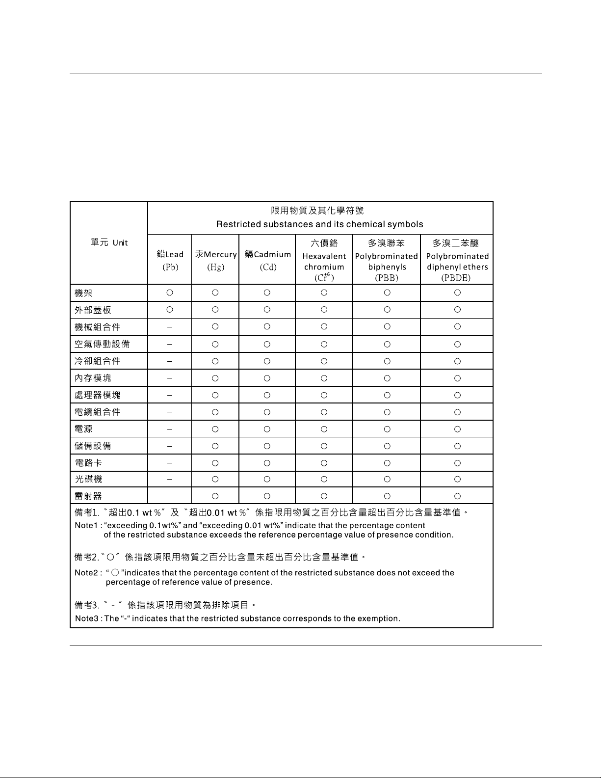
Electronic emission notices
When you attach a monitor to the equipment, you must use the designated monitor cable and any
interference suppression devices that are supplied with the monitor.
Additional electronic emissions notices are available at:
http://thinksystem.lenovofiles.com/help/index.jsp
Taiwan BSMI RoHS declaration
Taiwan import and export contact information
Contacts are available for Taiwan import and export information.
Appendix B. Notices 181
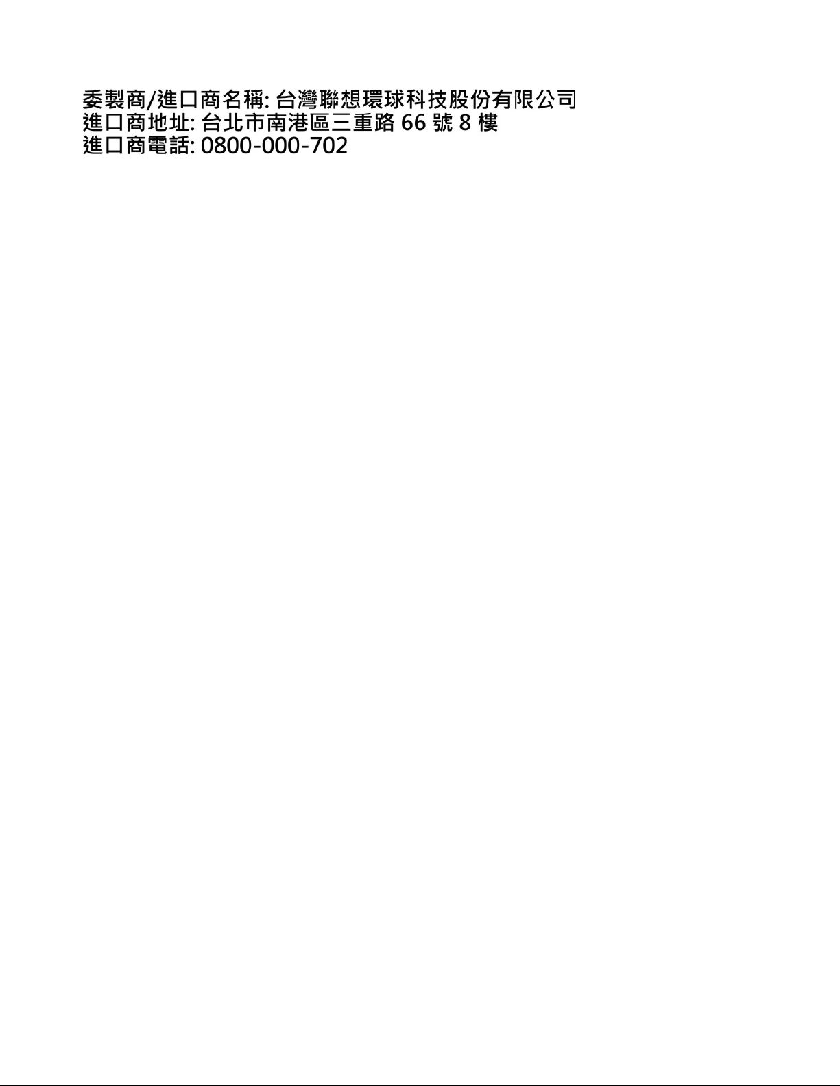
182 ThinkSystem ST50 V2 Maintenance Manual