Loading ...
Loading ...
Loading ...
6
1. Introduction
3378
12
46 5 109
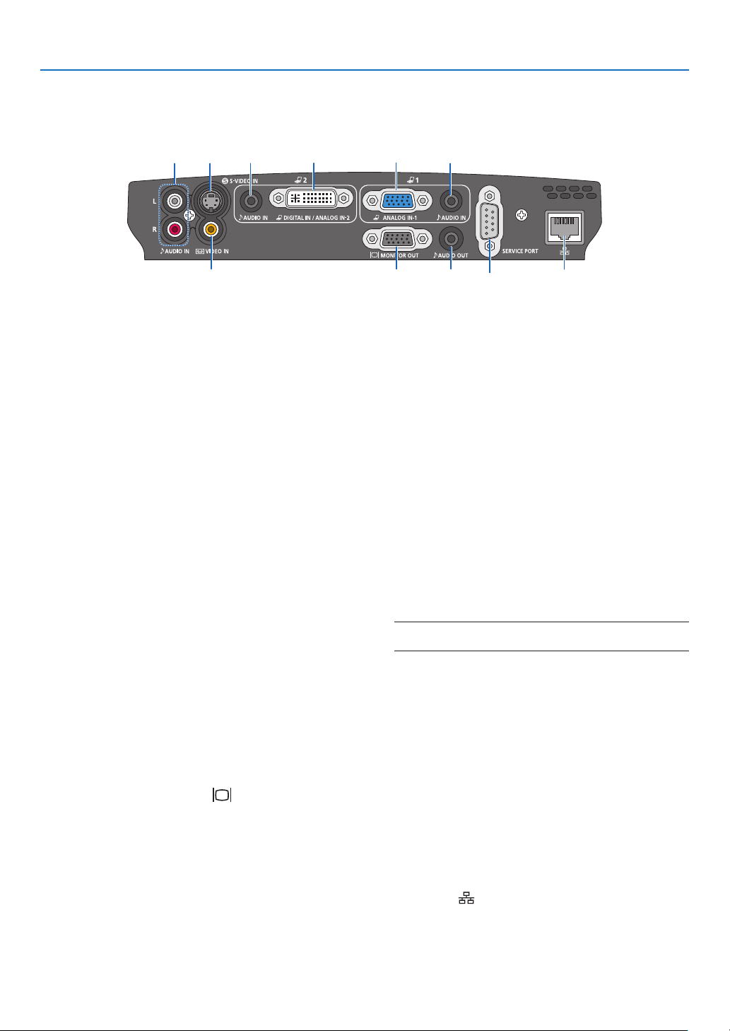
Terminal Panel Features
1. Computer 1 Input Connector [ANALOG IN-1]
(Mini D-Sub 15 Pin)
Connect your computer or other analog RGB equip-
ment such as IBM compatible or Macintosh com-
puters. Use the supplied VGA cable to connect to
your computer. This also serves as a component
input connector that allows you to connect a com-
ponent video output of audio-video equipment.
See page 14, 17, 19.
2. Computer 2 Input Connector [DIGITAL IN/ANA-
LOG IN-2] (DVI-I 29 Pin)
Connect the DVI output of your computer or other
digital RGB equipment such as IBM compatible or
Macintosh computers.
You can also use the supplied DVI to VGA adapter to
connect the output of analog RGB equipment.
See page 16, 17, 21.
3. AUDIO IN Mini Jack (Stereo Mini)
This is where you connect the audio output from
your computer or audio-video equipment when con-
nected to the ANALOG IN-1 or 2 input. A commer-
cially available audio cable is required.
See page 14, 16, 18, 19, 21.
4.
MONITOR OUT Connector [ ] (Mini D-Sub 15 Pin)
You can use this connector to loop your computer im-
age to an external monitor from the RGB input source
(ANALOG IN-1).
This connector outputs RGB signal in standby
mode. See page 18.
5. AUDIO OUT Mini Jack (Stereo Mini)
You can use this jack to output sound to your audio-
video equipment from the currently selected source.
Output sound level can be adjusted in accordance
with the sound level of the internal speaker.
Note that this cannot be used as a headphone jack.
(When audio equipment is connected, the projector
speaker is disabled.)
When a cable mini-plug is inserted into this jack, both the
right and left audio signals are not mixed, but separate.
For example, when a cable mini-plug is inserted into
the left AUDIO IN jack only, only left sound is output.
6. VIDEO IN Connector (RCA)
Connect audio-video equipment here to project video.
See page 20.
7. S-VIDEO IN Connector (Mini DIN 4 Pin)
Here is where you connect the S-Video input from
audio-video equipment.
See page 20.
NOTE: S-Video provides more vivid color and higher reso-
lution than the traditional composite video format.
8. AUDIO IN Jacks L/R (RCA)
These are your left and right channel audio inputs for
stereo sound from a Video/S-Video source.
See page 20, 21.
9. SERVICE PORT (D-Sub 9 Pin)
Use this port to connect a computer or control sys-
tem.
This enables you to control the projector using se-
rial communication protocol. If you are writing your
own program, typical PC control codes are on page
84.
10. LAN Port [
] (RJ-45)
Use this port when controlling your projector in LAN
connection from a computer. Use a commercially
available LAN cable (10 Base-T/100 Base-T) to con-
nect the projector to the computer. See page 22.
Loading ...
Loading ...
Loading ...