
Loading ...
Loading ...
Loading ...
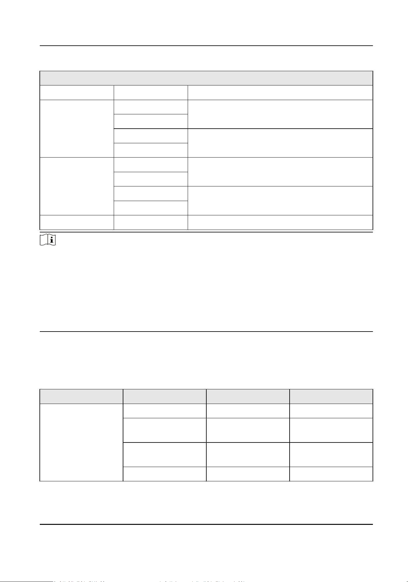
Access Control Board Terminal Descripon
K1 Door 1 Signal Input
Door Lock D1- Door 1 Relay Output (Dry Contact)
D1+
D2- Door 2 Relay Output (Dry Contact)
D2+
Alarm Output1/
Alarm Output 2
NO/NC1 Alarm Output Relay 1 (Dry Contact)
COM1
NO/NC2 Alarm Output Relay 2 (Dry Contact)
COM2
Network Interface LAN Network Accessing
Note
●
The alarm input hardware interface is normally open by default. So only the normally open
signal is allowed. It can be linked to the buzzer of the card reader and access controller, and the
alarm relay output and open door relay output.
●
The DIP of RS485 card ID is set as 1 and 4 by default. 1 is for entering, and 4 is for exing. Set the
DIP as 3 for connecng visitor card reader.
●
The Wiegand card reader 1 and 2 respecvely refer to the entering and exing card reader.
●
The alarm output supports relay output.
●
For detailed informaon about the DIP switch, see DIP Switch Descripon.
BUS Descripon
You can use the BUS to connect card reader, ngerprint module, etc.
Table 4-2 Table of BUS Terminal Descripon
Terminal Group Terminal Name Color Descripon
Fingerprint Module
Terminal Group
5V Red 5 V Power Terminal
485/232+ Purple Connect to Fingerprint
Module RS-485+
485/232- Yellow Connect to Fingerprint
Module RS-485-
GND Black Grounding
DS-K3G501SX Series Tripod Turnsle User Manual
13
Loading ...
Loading ...
Loading ...