Loading ...
Loading ...
Loading ...
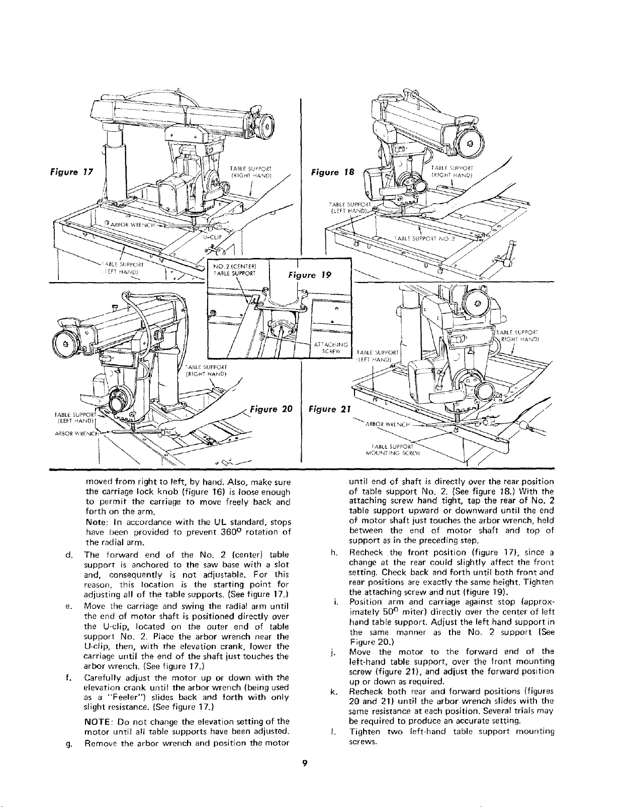
Figure 18
(LEFT
I
2
Figure 21
ABLE SUPPORT
MOUNT [NG 5C
moved from right to left, by hand, Also, make sure
the carriage lock knob (figure 16) is loose enough
to permit the carriage to move freely back and
forth on the arm.
Note: In accordance with the UL standard, stops
have been provided to prevent 360 ° rotation of
the radial arm,
d. The forward end of the No. 2 (center) table
support is anchored to the saw base with a slot
and, consequently is not adjustable. For this
reason, this location is the starting point for
adjusting all of the table supports. (See figure 17.)
e. Move the carriage and swing the radial arm until
the end of motor shaft is positioned directly over
the U-clip, located on the outer end of table
support No. 2. Place the arbor wrench near the
U-clip, then, with the elevation crank, lower the
carriage until the end of the shaft just touches the
arbor wrench. (See figure 17.)
f. Carefully adjust the motor up or down with the
elevation crank until the arbor wrench (being used
as a "Feeler") slides back and forth with only
slight resistance. (See figure 17.)
NOTE: Do not change the elevation setting of the
motor until all table supports have been adjusted.
g. Remove the arbor wrench and position the motor
until end of shaft is directly over the rear position
of table support No. 2. (See figure 18.) With the
attaching screw hand tight, tap the rear of No. 2
table support upward or downward until the end
of motor shaft just touches the arbor wrench, held
between the end of motor shaft and top of
support as in the preceding step.
h. Recheck the front position (figure 17), since a
change at the rear could slightly affect the front
setting. Check back and forth until both front and
rear positions are exactly the same height. Tighten
the attaching screw and nut (figure 19).
i. Position arm and carriage against stop (approx-
imately 50 ° miter) directly over the center of left
hand table support. Adjust the left hand support in
the same manner as the No. 2 support {See
Figure 20.)
j. Move the motor to the forward end of the
left-hand table support, over the front mounting
screw (figure 21), and adjust the forward position
up or down as required.
k. Recheck both rear and forward positions (figures
20 and 21) until the arbor wrench slides with the
same resistance at each position. Several trials may
be required to produce an accurate setting.
I. Tighten two left-hand table support mounting
screws.
Loading ...
Loading ...
Loading ...