Loading ...
Loading ...
Loading ...
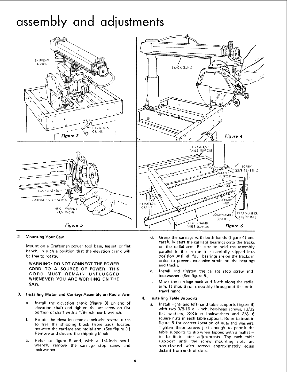
assembly and adjustments
BLOCK
CARRIAGE STOP SCREW
14EX-L WRENCH _ .)
0/4 rNCH)
Figure 5
LEFT-HAND
TABLE SUPPORT
I [ TABLE SUPPORf
Figure 4
SCREW
3/8-16 x I IN.)
2.. Mounting Your Saw
Mount on a CrafLsman power tool base, leg set, or flat
bench, in such a position that the elevation crank will
be free to rotate.
WARNING: DO NOT CONNECT THE POWER
CORD TO A SOURCE OF POWER, THIS
CORD MUST REMAIN UNPLUGGED
WHENEVER YOU ARE WORKING ON THE
SAW.
3, Installing Motor and Carriage Assembly on Radial Arm
Install the elevation crank (figure 3} on end of
elevation shaft and tighten the set screw on flat
portion of shaft with a 1/8-inch hex-L wrench.
Rotate the elevation crank clockwise several turns
to free the shipping block (fibre pad), located
between the carriage and radial arm. (See figure 3.)
Remove and discard the shipping block.
Refer to figure 5 and, with a 1/4-inch hex L
wrench, remove the carriage stop screw and
Iockwasher.
LOCKWASHER FLAT WASHER
(13/32 IN.)
(3/8 In .)
Figure 6
d. Grasp the carriage with both hands (figure 4) and
carefully start the carriage bearings onto the tracks
on the radial arm, Be sure to hold the assembly
parallel to the arm as it is carefully slipped into
position until all four bearings are on the tracks in
order to prevent excessive strain on the bearings
and tracks.
e, Install and tighten the cariage stop screw and
Iockwasher. (See figure 5.)
f. Move the carriage back and forth along the radial
arm. It should roll smoothly throughout the entire
travel range.
Installing Table Supports
a. Install right- and left-hand table supports (figure 6)
with two 3/8-16 x 1-inch, hex-head screws, 13/32
flat washers, 3/8-inch Iockwashers and 3/8-16
square nuts in each table support. Refer to inset in
figure 6 for correct location of nuts and washers.
Tighten these screws just enough to permit the
table supports to slip when tapped with a mallet -
to facilitate later adjustments. Tap each table
support until the screw mounting slots are
positioned with screws approximately equal
distant from ends of slots.
6
Loading ...
Loading ...
Loading ...