Loading ...
Loading ...
Loading ...
ADDITIONAL SAFETY INSTRUCTIONS FOR RADIAL SAWS
WEAR YOUR
The operation of any power tool can result in foreign
objects being thrown into the eyes, which can result in
severe eye damage. Always wear safety goggles complying
with ANSI Z87.1 (shown on Package) before commencing
power tool operation. Safety Goggles are available at Sears
retail or catalog stores.
Page
Operating Controls ............................ 15
Basic Saw Operations ........................... 18
Trouble Shooting .............................. 21
Motor Trouble Shooting Chart ................ 25-26
Repair Parts .................................. 28
3/8-inch wrench
7/16-inch wrench
1!2-inch wrench
9/16-inch wrench
CONTENTS
Page
Guarantee and General Safety Instructions ........... 2
Additional Safety Instructions to Operator ........... 3
Unpacking and Pre-Assembly Instructions ............ 5
Assembly and Adjustments ....................... 6
Electrical Connections .......................... 13
F-'
TOOLS NEEDED /:_ li
S rewOrlver(smo,,) I::
_._ _ Framing square i "
Pencil Figure f Pliers _: ,: !
unpacking and pre-assembly
1. Unpacking and Checking Contents
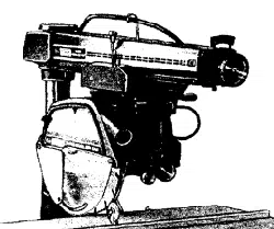
a. Before proceeding with the assembly of your new
Craftsman 12-Inch Radial saw, you should read
these instructions and follow them carefully.
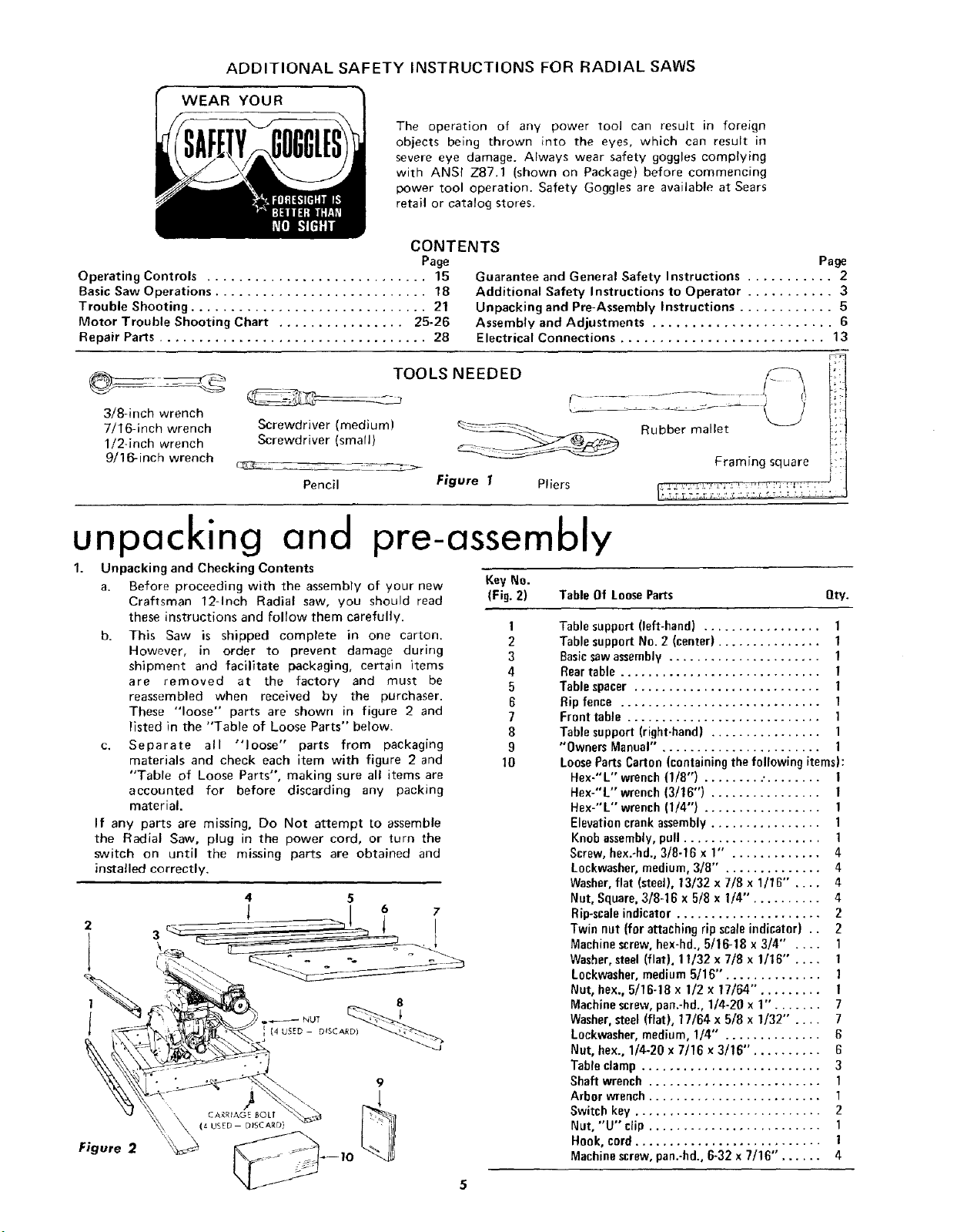
b. This Saw is shipped complete in one carton.
However, in order to prevent damage during
shipment and facilitate packaging, certain items
are removed at the factory and must be
reassembled when received by the purchaser.
These "loose" parts are shown in figure 2 and
listed in the "Table of Loose Parts" below.
c, Separate all "loose" parts from packaging
materials and check each item with figure 2 and
"Table of Loose Parts", making sure all items are
accounted for before discarding any packing
material.
If any parts are missing, Do Not attempt to assemble
the Radial Saw, plug in the power cord, or turn the
switch on until the missing parts are obtained and
installed correctly.
Key No.
(Fig. 2) Table Of Loose Parts Qty.
I
2
3
4
5
6
7
8
9
10
2
4 5
8
Figure 2
Tablesupport (left-hand) ................. 1
Tablesupport No. 2 (center) ............... 1
Basicsawassembly...................... 1
Reartable ............................. 1
Tablespacer ........................... 1
Ripfence ............................. 1
Fronttable ............................ 1
Tablesupport(right-hand) ................ 1
"Owners Manual" ....................... 1
LoosePartsCarton (containingthefollowing items):
Hex-"L" wrench(1/8") ......... •........ 1
Hex-"L" wrench(3/16") ................ 1
Hex-"L" wrench(1/4") ................. 1
Elevationcrankassembly................ 1
Knobassembly,pull .................... 1
Screw,hex.-hd.,3/8-16 x 1" . ............ 4
Lockwasher, medium,3/8" . ............. 4
Washer,flat (steel),13/32 x 7/8 x 1/16" .... 4
Nut, Square,3/8-16 x 5/8 x 1/4". ......... 4
Rip-scaleindicator..................... 2
Twin nut (for attaching ripscaleindicator) .. 2
Machinescrew,hex-hd.,5/16-18 x 3/4" .... 1
Washer,steel(flat), 11/32 x 7/8 x 1/16" .... 1
Lockwasher,medium5/16"'. ............. 1
Nut, bex., 5/16-18 x 1/2 x 17/64". ........ 1
Machinescrew,pan.-hd.,1/4-20 x 1". ...... 7
Washer.steel(flat), 17/64 x 5/8 x 1/32" .... 7
Lockwasher,medium,1/4" .............. 6
Nut, hex., 1/4-20 x 7/16 x 3/16". ......... 6
Tableclamp .......................... 3
Shaft wrench ......................... 1
Arbor wrench......................... 1
Switch key ........................... 2
Nut, "'U'"clip ......................... 1
Hook,cord........................... !
Machinescrew,pan.-hd.,6-32 x 7/16". ..... 4
Loading ...
Loading ...
Loading ...