Loading ...
Loading ...
Loading ...
operating controls
1
/
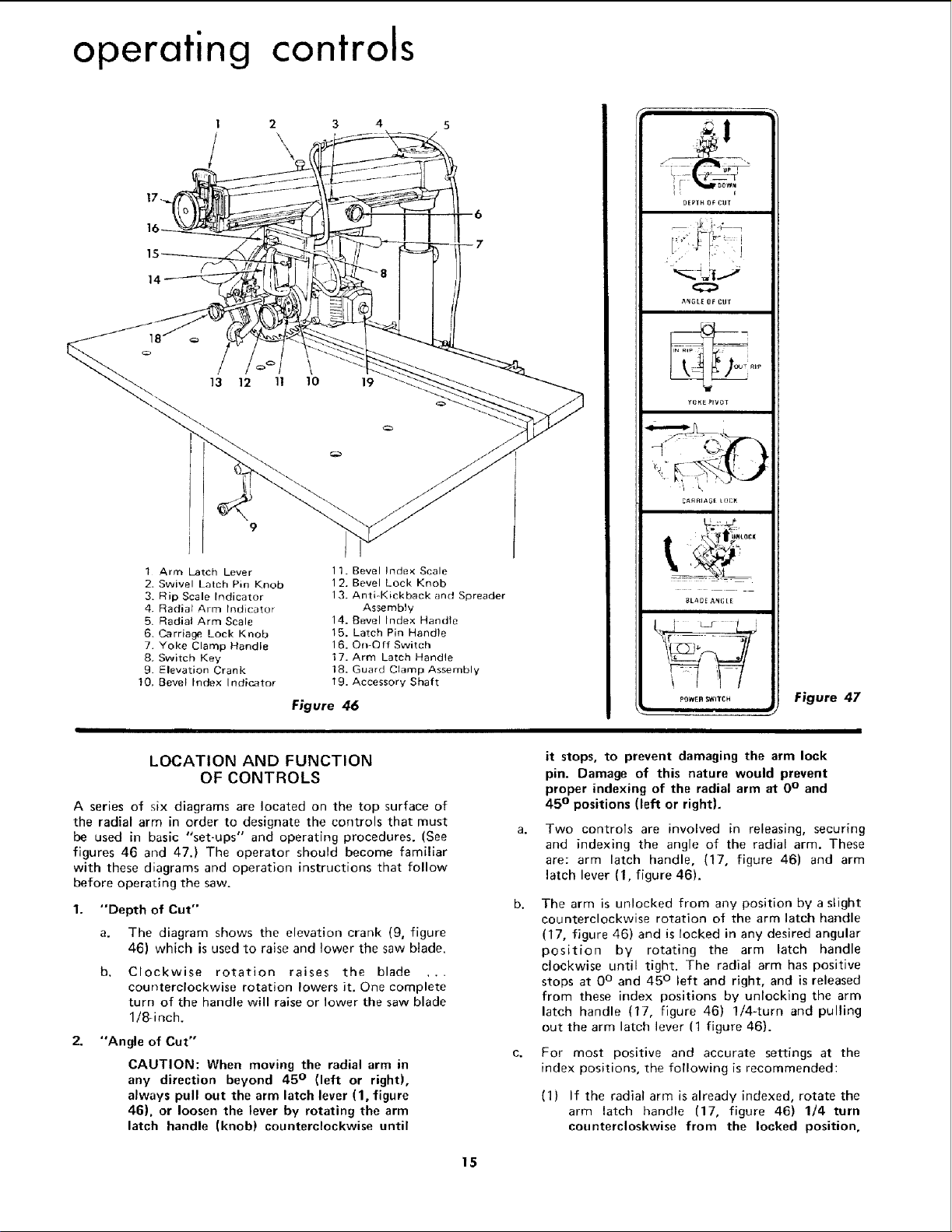
1 Arm Latch Lever
2. Swivel Lalch Pin Knob
3, Rip Scale Indicator
4 Radia_ Arm Indicator
5. Radial Arm Scale
6. Carriage Lock Knob
7. Yoke Clamp Handle
8. Switch Key
9. Elevation Crank
t0, Bevel Index Indicator
2
\
3 4 5
1 1. Bevel Index Scale
12. Bevel Lock Knob
13. Anti-Kickback and Spreader
Assembly
14. Bevel Index Handle
15. Latch Pin Handle
16. On-Off Switch
17. Arm Latch Handle
18. Guard Clamp Assembly
19. Accessory Shaft
Figure 46
DEPIH OF CUT
O
,_NGLE OF CUr
_ARRIAS[ L()1:_
BLADE ANI;LE
POWER WITCH
w
Figure 47
LOCATION AND FUNCTION
OF CONTROLS
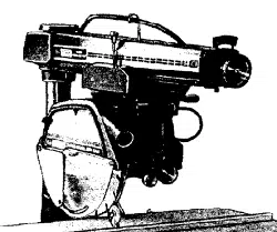
A series of six diagrams are located on the top surface of
the radial arm in order to designate the controls that must
be used in basic "set-ups" and operating procedures. (See
figures 46 and 47.) The operator should become familiar
with these diagrams and operation instructions that follow
before operating the saw.
1. "Depth of Cut"
a. The diagram shows the elevation crank (9, figure
46) which is used to raise and lower the saw blade.
Clockwise rotation raises the blade ...
counterclockwise rotation lowers it. One complete
turn of the handle will raise or lower the saw blade
1/8-inch.
2. "Angle of Cut"
CAUTION: When moving the radial arm in
any direction beyond 45 ° (left or right),
always pull out the arm latch lever (1, figure
46), or loosen the lever by rotating the arm
latch handle (knob) counterclockwise until
C.
it stops, to prevent damaging the arm lock
pin. Damage of this nature would prevent
proper indexing of the radial arm at 0° and
45 ° positions (left or right).
Two controls are involved in releasing, securing
and indexing the angle of the radial arm. These
are: arm latch handle, (17, figure 46) and arm
latch lever (1, figure 46).
The arm is unlocked from any position by a slight
counterclockwise rotation of the arm latch handle
(17, figure 46) and is locked in any desired angular
position by rotating the arm latch handle
clockwise until tight. The radial arm has positive
stops at 0° and 45 ° left and right, and is released
from these index positions by unlocking the arm
latch handle (17, figure 46) 1/4-turn and pulling
out the arm latch lever (1 figure 46).
For most positive and accurate settings at the
index positions, the following is recommended:
(I) If the radial arm is already indexed, rotate the
arm latch handle (17, figure 46) I/4 turn
countercloskwise from the locked position,
15
Loading ...
Loading ...
Loading ...