Loading ...
Loading ...
Loading ...
assembly and adjustments
TABLE
SPACER
Figure 35
EV¢Iv_E[ L_TDH PIN K_OB
YOKE CLAMP
HANDLE
"rOKE
Figure 36 o o rE_<
CARRIAGE
LOCK KNOB
I
REAR
Figure 37
C,\RRbXGE LOCK KNOB
0
Figure 38
©
_ MEAS:JRE FROM
FENCE _O NEARESJ"
BLADE TOOTH
m/ X-..." i,
.' FRONT ";ABLE
PENCE REAR fABLE TABLE SPACER
BOARD
Figure 39
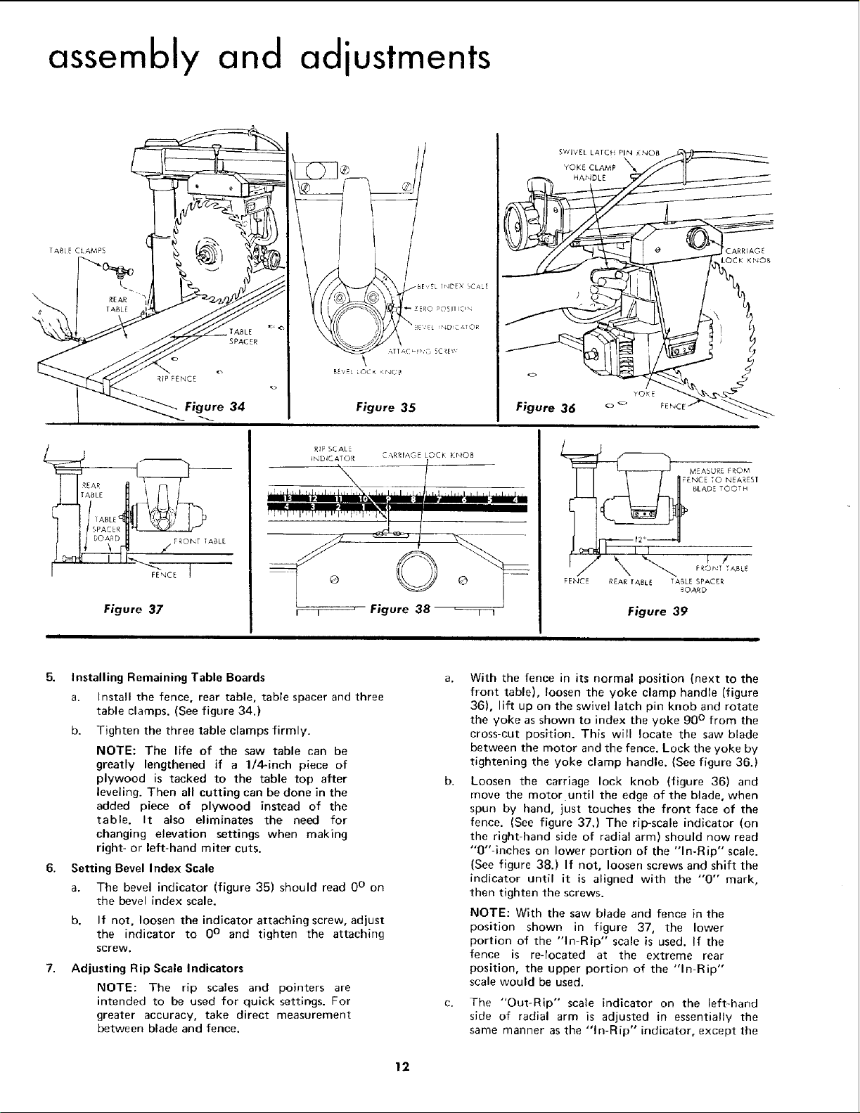
5. Installing Remaining Table Boards
a. Install the fence, rear table, table spacer and three
table clamps. (See figure 34.)
b. Tighten the three table clamps firmly.
NOTE: The life of the saw table can be
greatly lengthened if a 1/4-inch piece of
plywood is tacked to the table top after
leveling. Then all cutting can be done in the
added piece of plywood instead of the
table. It also eliminates the need for
changing elevation settings when making
right- or left-hand miter cuts.
6. Setting Bevel Index Scale
a. The bevel indicator (figure 35) should read 0° on
the bevel index scale.
b. If not, loosen the indicator attaching screw, adjust
the indicator to 0° and tighten the attaching
screw.
Adjusting Rip Scale Indicators
NOTE: The rip scales and pointers are
intended to be used for quick settings. For
greater accuracy, take direct measurement
between blade and fence.
With the fence in its normal position (next to the
front table), loosen the yoke clamp handle (figure
36), lift up on the swivel latch pin knob and rotate
the yoke as shown to index the yoke 90 ° from the
cross-cut position. This will locate the saw blade
between the motor and the fence. Lock the yoke by
tightening the yoke clamp handle. (See figure 36.)
Loosen the carriage lock knob (figure 36) and
move the motor until the edge of the blade, when
spun by hand, just touches the front face of the
fence. (See figure 37.) The rip-scale indicator (on
the right hand side of radial arm) should now read
"0"-inches on lower portion of the "In-Rip" scale.
(See figure 38.) If not, loosen screws and shift the
indicator until it is aligned with the "'0" mark,
then tighten the screws.
NOTE: With the saw blade and fence in the
position shown in figure 37, the lower
portion of the "In-Rip" scale is used. If the
fence is re-located at the extreme rear
position, the upper portion of the "In-Rip"
scale would be used.
The "Out-Rip" scale indicator on the left-hand
side of radial arm is adjusted in essentially the
same manner as the "In-Rip" indicator, except the
12
Loading ...
Loading ...
Loading ...