Loading ...
Loading ...
Loading ...
SOCKE_{
SEf SCREV,
IFOUR TOIAL)
(2)
BEVEL LOCK KNOB
ECCENTRIC
SCREW
lEVEL iNDEX
SCALE
_,OR
Figure 65
ECCENTRIC
SCREW
Figure 68 Figure 69
If the saw blade is square with the table top,
the square will contact the hollow-ground
blade at the points shown by arrows in figure
64. If the square does not touch the saw blade
as shown (with square leg held firm against
the table top), perform the following
adjustments:
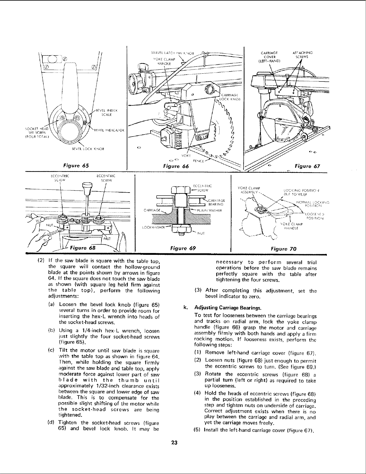
(a) Loosen the bevel lock knob (figure 65)
several turns in order to provide room for
inserting the hex-L wrench into heads of
the socket-head screws.
(b) Using a 1/4-inch hex-L wrench, loosen
just slightly the four socket-head screws
(figure 65).
(c) Tilt the motor until saw blade is square
with the table top as shown in figure 64.
Then, while holding the square firmly
against the saw blade and table top, apply
moderate force against lower part of saw
blade with the thumb until
approximately 1/32-inch clearance exists
between the square and lower edge of saw
blade. This is to compensate for the
possible slight shifting of the motor while
the socket-head screws are being
tightened.
(d) Tighten the socket-head screws (figure
65) and bevel lock knob. It may be
CARRIAGE
COVER
{LEFT-HAND)
BEARING
YOKE CLAMP
ASSEMBLY.
ATTACHNG
SCREWS
Figure 67
Figure 70
necessary to perform several trial
operations before the saw blade remains
perfectly square with the table after
tightening the four screws.
(3) After completing this adjustment, set the
bevel indicator to zero.
Adjusting Carriage Bearings.
To test for looseness between the carriage bearings
and tracks on radial arm, lock the yoke clamp
handle (figure 66) grasp the motor and carriage
assembly firmly with both hands and apply a firm
rocking motion. If looseness exists, perform the
following steps:
(1) Remove left-hand carriage cover (figure 67).
(2) Loosen nuts (figure 68) just enough to permit
the eccentric screws to turn. (See figure 69.)
(3) Rotate the eccentric screws (figure 68) a
partial turn (left or right) as required to take
up looseness.
(4) Hold the heads of eccentric screws (figure 68)
in the position established in the preceding
step and tighten nuts on underside of carriage.
Correct adjustment exists when there is no
play between the carriage and radial arm, and
yet the carriage moves freely.
(5) Install the left-hand carriage cover (figure 67).
23
Loading ...
Loading ...
Loading ...