Loading ...
Loading ...
Loading ...
assembly and adjustments
Figure 22
IFI[S HOLE NOT USED
IN TABLE _NSTALLAItON
LATCH
"4 HANDLE
_,_ FLAT ,_/ASH ER
(1/4 IN. ) TABLE SLJPPORI
WASHE R.?'_
(1/4 iN.)
ARM LAICH
HANDLE (K NOB)
BEVEL LOCK
KNOB
NUT
l I/4- 2O)
Figure 23 Figure 24
Figure 25
'€,'RENC h
Figure 27
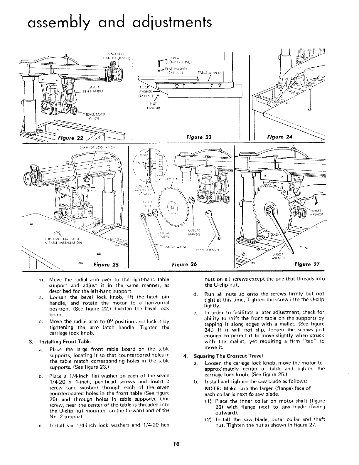
m. Move the radial arm over to the right-hand table
support and adjust it in the same manner, as
described for the left-hand support.
n. Loosen the bevel lock knob, lift the latch pin
handle, and rotate the motor to a horizontal
position. (See figure 22.) Tighten the bevel lock
knob.
o. Move the radial arm to 0° position and lock it by
tightening the arm latch handle. Tighten the
carriage lock knob.
Installing Front Table
a. Place the large front table board on the table
supports, locating it so that eounterbored holes in
the table match corresponding holes in the table
supports. (See figure 23.)
b. Place a 1/4-inch flat washer on each of the seven
1/4-20 x 1-inch, pan-head screws and insert a
screw (and washer) through each of the seven
eounterboared holes in the front table (See figure
25) and through holes in table supports. One
screw, near the center of the table is threaded into
the U-clip nut mounted on the forward end of the
No, 2 support.
c. Install six 1/4-inch lock washers and 1/4-20 hex
4.
nuts on all screws except the one that threads into
the U-clip nut.
d. Run all nuts up onto the screws firmly but not
tight at this time. Tighten the screw into the U-clip
lightly.
In order to facilitate a later adjustment, check for
ability to shift the front table on the supports by
tapping it along edges with a mallet. (See figure
24.) If it will not slip, loosen the screws just
enough to permit it to move slightly when struck
with the mallet, yet requiring a firm "tap" to
move it.
Squaring The Crosscut Travel
a. Loosen the cariage lock knob, move the motor to
approximately center of table and tighten the
carriage lock knob. (See figure 25.)
b. Install and tighten the saw blade as follows:
NOTE: Make sure the larger (flange) face of
each collar is next tb saw blade.
(1) Place the inner collar on motor shaft (figure
26) with flange next to saw blade (facing
outward).
(2) Install the saw blade, outer collar and shaft
nut. Tighten the nut as shown in figure 27.
10
Loading ...
Loading ...
Loading ...