Loading ...
Loading ...
Loading ...
NUT
5.
NO.2
SUPPORT
Figure 7
MrTER SCALE
INDICATOR
CORD
CLIP
Figure 9
LATCH
PiN HAPJ
BEVEL LOCK
I
Figure 8
SCREW (No.6 32×7/i6 IN.PAN HD.)
A
R H CARRIAGE '_
' dOVER I _1 RIPSCAL_
\ @_"_ IN DIC AT OR
Figure I0
CARRIAGE
LOCK KNOB
bASE
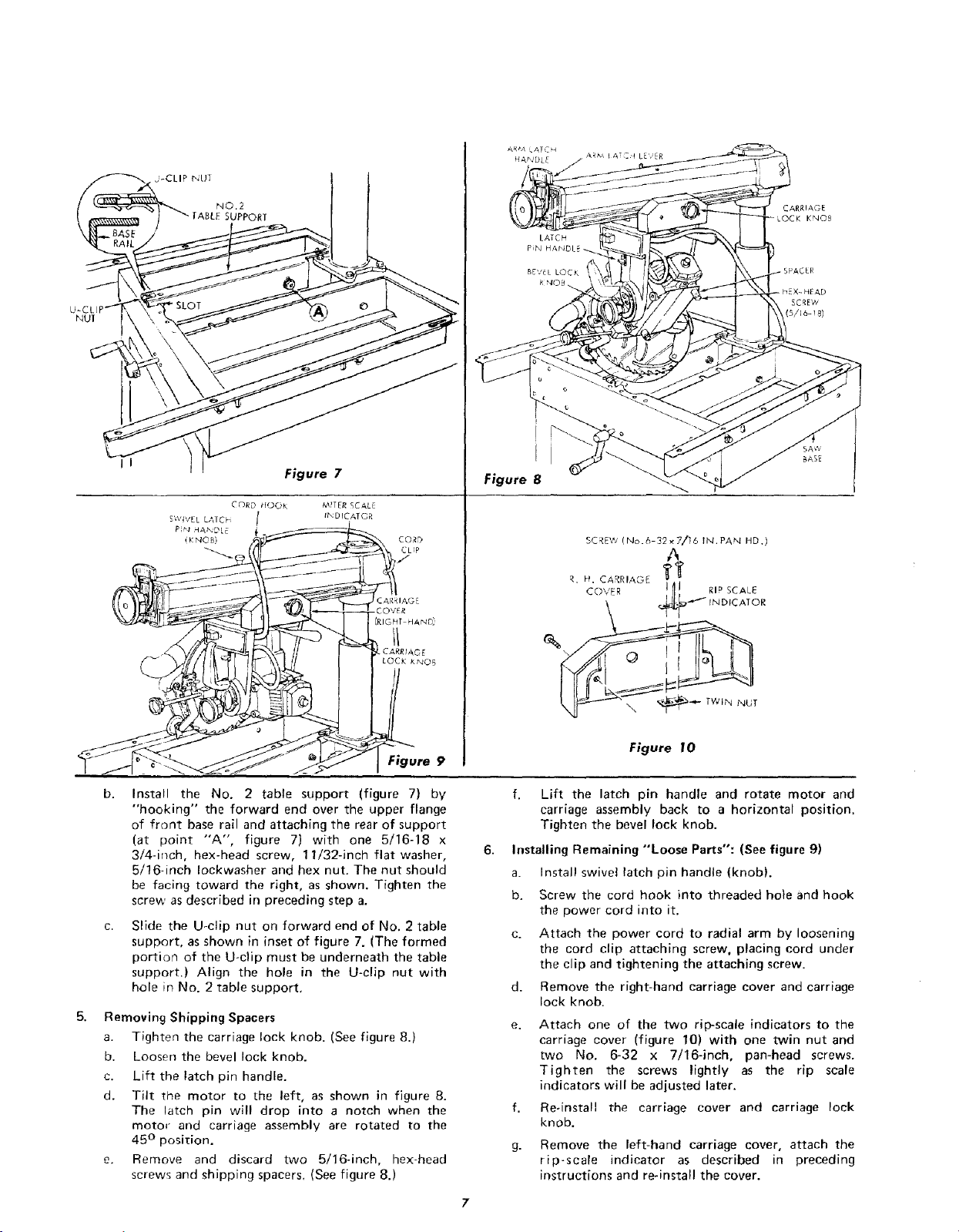
Install the No. 2 table support (figure 7) by
"hooking" the forward end over the upper flange
of front base rail and attaching the rear of support
(at point "'A', figure 7) with one 5/16-18 x
3/4-inch, hex-head screw, 11/32-inch flat washer,
5/16-inch Iockwasher and hex nut. The nut should
be facing toward the right, as shown. Tighten the
screw as described in preceding step a.
Slide the U-clip nut on forward end of No. 2 table
support, as shown in inset of figure 7. (The formed
portion of the U-clip must be underneath the table
support.) Align the hole in the U-clip nut with
hole in No. 2 table support,
Removing Shipping Spacers
a. Tighten the carriage lock knob. (See figure 8.)
b. Loosen the bevel lock knob.
c. Lift the latch pin handle.
d. Tilt the motor to the left, as shown in figure 8.
The latch pin will drop into a notch when the
motor and carriage assembly are rotated to the
45 ° position.
e. Remove and discard two 5/16-inch, hex-head
screws and shipping spacers, (See figure 8.)
f. Lift the latch pin handle and rotate motor and
carriage assembly back to a horizontal position.
Tighten the bevel lock knob.
Installing Remaining "Loose Parts": (See figure 9)
a. Install swivel latch pin handle (knob).
b. Screw the cord hook into threaded bole and hook
the power cord into it.
c. Attach the power cord to radial arm by loosening
the cord clip attaching screw, placing cord under
the clip and tightening the attaching screw.
d. Remove the right-hand carriage cover and carriage
lock knob.
e. Attach one of the two rip-scale indicators to the
carriage cover (figure 10) with one twin nut and
two No. 6-32 x 7/16-inch, pan-head screws.
Tighten the screws lightly as the rip scale
indicators will be adjusted later.
f. Re-install the carriage cover and carriage lock
knob.
g. Remove the left-hand carriage cover, attach the
rip-scale indicator as described in preceding
instructions and re-install the cover.
Loading ...
Loading ...
Loading ...