Loading ...
Loading ...
Loading ...
desired angle of cut; yoke and bevel settings indexed at 0°
(and locked) as in square crosscutting. The board being cut
is hetd firmly against the fence and the carriage pulled
forward along the radial arm to perform the desired cut. As
in "Operation No. 1", the carriage should be r-eturned to
full rear position and the saw blade allowed to come to a
comolete stoo before removinQ the boards from saw t_ble.
OPERATION No. 3 - BEVEL CROSSCUT
Bevel crosscutting is the process of sawing at g0 ° (square)
across the board with the saw blade set at an angle other
than g0 ° to the saw table. (See figure 55.) The radial arm
and yoke are indexed at 0° and locked, but the bevel is set
to the desired angle of cut. The board is held firmly against
the fence and the carriage pulled forward along the radial
arm to produce the cut. The carriage should be returned to
full rearward position and the saw blade allowed co come to
a complete stop before removing the boards from saw table.
OPERATION No. 4 - COMPOUND
CROSSCUT
Compound crosscutting is the combination of miter and
bevel crosscuts. (See figure 56.) The radial arm arrd bevel
are set to produce the desired cut; the yoke is indexed at O°
and locked. The board is held firmly against the fence and
the carriage pulled forward along the radial arm to produce
the cut. Again, the carriage should be returned to full
rearward position and the saw blade allowed to come to a
complete stop before removing boards from saw table.
REQUIREMENTS WHEN RIPPING
(OPERATIONS 5 AND 6)
1. Carriage lock knob must be tight.
2. Radial arm must be locked in 0° position.
3. Work must be held firmly against table and fence while
feeding through.
4. Guard and anti-kickback mechanism must be properly
set. Observe instructions in paragraph, "Adjusting
Guard, and Anti-Kickback and Spreader Assembly, for
Ripping."
5. Blade should be sharp and correclty set.
6. Hands must be kept well away from saw blade.
When ripping narrow or short stock, always use a
push-board.
7. Saw blade must be parallel to fence, to minimize
possibility of kickbacks.
OPERATION No. 5 -- OUT-RIPPING
AND IN-RIPPING
1. Ripping is the process of sawing the workpiece by
feeding ;t into the saw blade when using the fence as a
guide and as a positioning device to obtain the desired
width of cut. (See figures 57 through 5g.)
2.
Provide a straight edge, even if this means temporary
nailing of an auxiliary straight-edged board to the
work. If the workpiece is warped, turn the hollow side
down.
3. Always use the saw guard and make sure the spreader is
correctly aligned with the saw kerf. Wood cut with the
grain tends to spring the kerf closed and bind the blade
and a kickback could occur.
4. Stand a little to one side of center to avoid being
sprayed with sawdust and to be clear of work in case of
kickback.
5. When ripping short or narrow work, always use a push
stick applied to the section of the workpiece between
the blade and fence ... push the work past the blade
so it is clear of the blade. This procedure will minimize
the possibility of kickbacks.
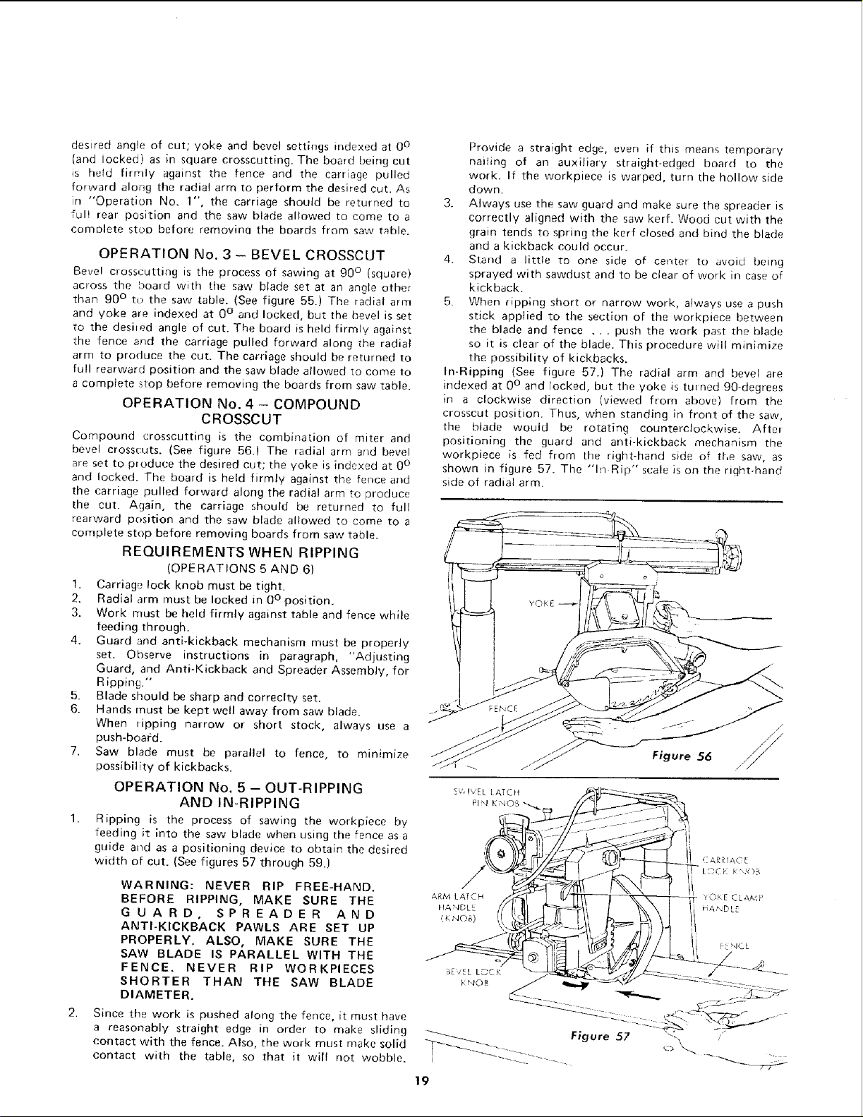
In-Ripping (See figure 57.) Time radial arm and bevel are
indexed at 0° and locked, but the yoke is twned 90-degrees
in a clockwise direction (viewed from above) from the
crosscut position. Thus, when standing in front of the saw,
the blade would be rotating counterclockwise. After
positioning the guard and anti-kickback mechanism the
workpiece is fed from the right-hand side of the saw, as
shown in figure 57. The "in Rip" scale is on the right-hand
side of radial arm.
WARNING: NEVER RIP FREE-HAND.
BEFORE RIPPING, MAKE SURE THE Am_L,_rCH
HANDLE
G U A R D, SPREADER AND _',K_Jo_)
ANTI-KICKBACK PAWLS ARE SET UP
PROPERLY. ALSO, MAKE SURE THE
SAW BLADE IS PARALLEL WITH THE
FENCE. NEVER RIP WORKPIECES BE/ELLOCK
SHORTER THAN THE SAW BLADE _r,_o_
DIAMETER.
Since the work is pushed along the fence, it must have
a reasonably straight edge in order to make sliding
contact with the fence. Also, the work must make solid
contact with the table, so that it will not wobble.
OKE CLAMP
HANDL
_-_ Figure 57
19
Loading ...
Loading ...
Loading ...