Loading ...
Loading ...
Loading ...
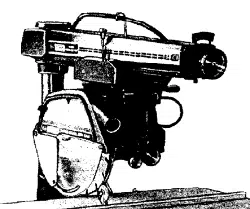
operating controls
3.
ARtd_ LATCH HANDLL
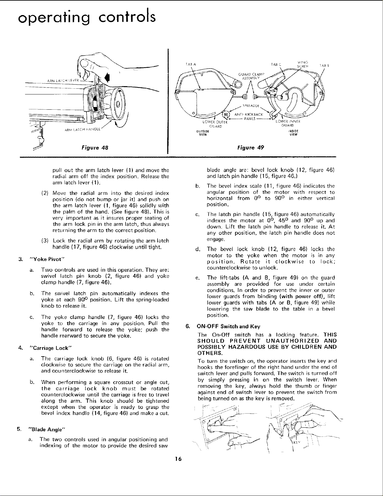
Figure 48
(2)
ZAB A
W'NG
TAB C SCREV_ TAB S
LOWER OUTER LOWER NNER
GUARD GUARD
OUTSIDE iNS1lie
VIEW VIEW
Figure 49
i
pull out the arm latch lever (1) and move the
radial arm off the index position. Release the
arm latch lever (I).
(3)
Move the radial arm into the desired index
position (do not bump or jar it) and push on
the arm latch lever (1, figure 46) solidly with
the palm of the hand. (See figure 48). This is
very important as it insures proper seating of
the arm lock pin in the arm latch, thus always
returning the arm to the correct position.
Lock the radial arm by rotating the arm latch
handle (17, figure 46) clockwise until tight.
"Yoke Pivot"
a. Two controls are used in this operation. They are:
swivel latch pin knob (2, figure 46) and yoke
clamp handle (7, figure 46).
b. The swivel latch pin automatically indexes the
yoke at each 90 ° position. Lift the spring-loaded
knob to release it.
C.
The yoke clamp handle (7, figure 46) locks the
yoke to the carriage in any position. Pull the
handle forward to release the yoke; push the
handle rearward to secure the yoke.
4. "Carriage Lock"
5_
a. The carriage lock knob (6, figure 46) is rotated
clockwise to secure the carriage on the radial arm,
and counterclockwise to release it.
b.
When performing a square crosscut or angle cut,
the carriage lock knob must be rotated
counterclockwise until the carriage is free to travel
along the arm. This knob should be tightened
except when the operator is ready to grasp the
bevel index handle (14, figure 46) and make a cut.
"Blade Angle"
a. The two controls used in angular positioning and
indexing of the motor to provide the desired saw
8.
16
b.
d.
blade angle are: bevel lock knob (12, figure 46)
and latch pin handle (15, figure 46.)
The bevel index scale (11, figure 46) indicates the
angular position of the motor with respect to
horizontal from 0° to 90 ° in either vertical
position.
The latch pin handle (15, figure 46)automatically
indexes the motor at 0°, 45 ° and 90 ° up and
down. Lift the latch pin handle to release it. At
any other position, the latch pin handle does not
engage.
The bevel lock knob (12, figure 46) locks the
motor to the yoke when the motor is in any
position. Rotate it clockwise to lock;
counterclockwise to unlock.
The lift-tabs (A and B, figure 49) on the guard
assembly are provided for use under certain
conditions. In order to prevent the inner or outer
lower guards from binding (with power off}, lift
lower guards with tabs (A or B, figure 49) while
lowering the saw blade to the table in a bevel
position.
ON-OFF Switch and Key
The On-Off switch has a locking feature. THIS
SHOULD PREVENT UNAUTHORIZED AND
POSSIBLY HAZARDOUS USE BY CHILDREN AND
OTHERS.
To turn the switch on, the operator inserts the key and
hooks the forefinger of the right hand under the end of
switch lever and pulls forward. The switch is turned off
by simply pressing in on the switch lever. When
removing the key, always hold the thumb or finger
against end of switch lever to prevent the switch from
being turned on as the key is removed.
i
I
t! ,
Loading ...
Loading ...
Loading ...