Loading ...
Loading ...
Loading ...
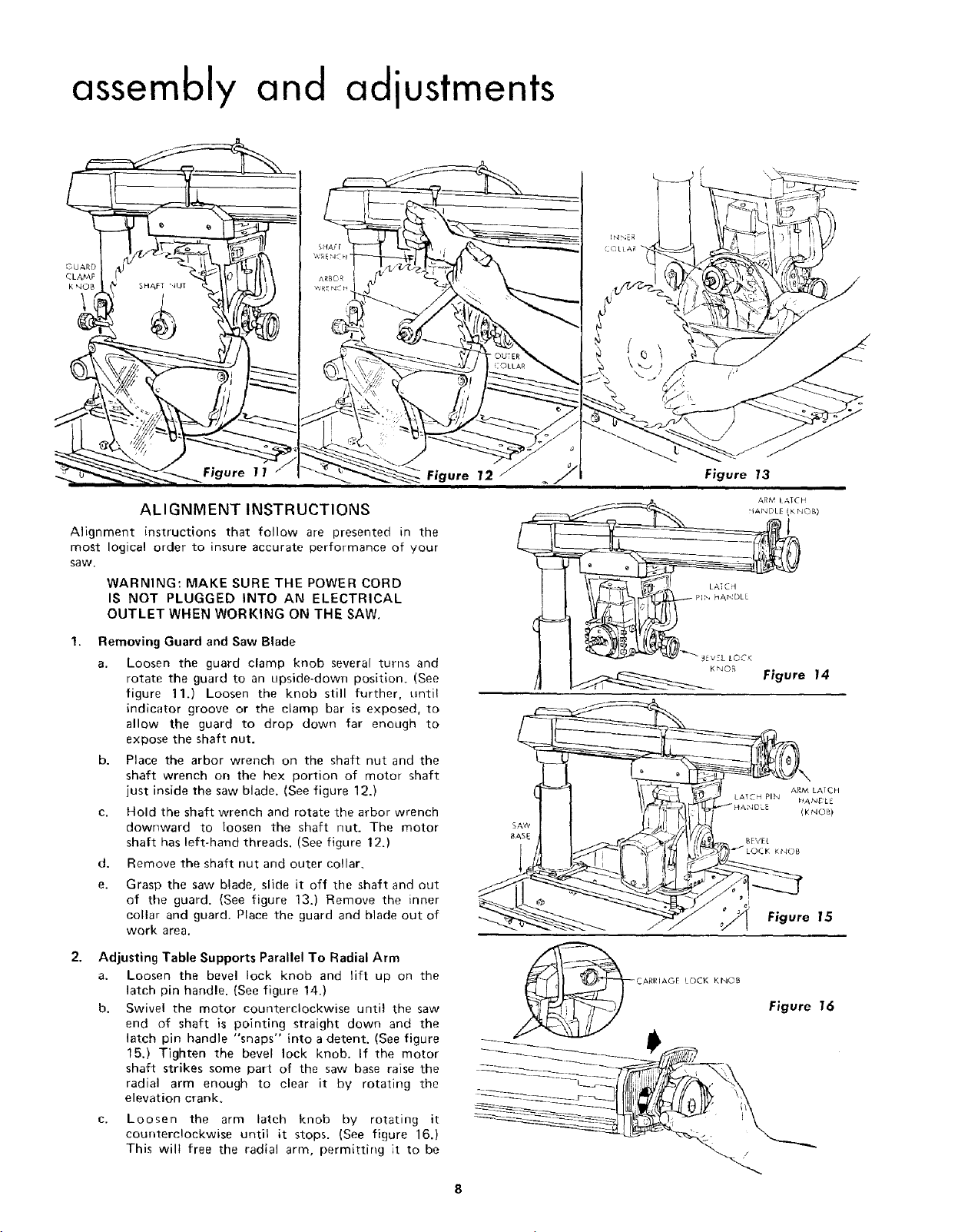
assembly and adiustments
Figure 11
ALIGNMENT INSTRUCTIONS
Alignment instructions that follow are presented in the
most logical order to insure accurate performance of your
saw.
WARNING: MAKE SURE THE POWER CORD
IS NOT PLUGGED INTO AN ELECTRICAL
OUTLET WHEN WORKING ON THE SAW.
Removing Guard and Saw Blade
a. Loosen the guard clamp knob several turns and
rotate the guard to an upside-down position. (See
figure 11.) Loosen the knob still further, until
indicator groove or the clamp bar is exposed, to
allow the guard to drop down far enough to
expose the shaft nut.
b. Place the arbor wrench on the shaft nut and the
shaft wrench on the hex portion of motor shaft
just inside the saw blade. (See figure 12.)
c. Hold the shaft wrench and rotate the arbor wrench
dowr_ward to loosen the shaft nut. The motor
shaft has left-hand threads. (See figure 12.)
d. Remove the shaft nut and outer collar,
e.
Grasp the saw blade, slide it off the shaft and out
of the guard. {See figure 13.) Remove the inner
collar and guard. Place the guard and blade out of
work area.
Adjusting Table Supports Parallel To Radial Arm
a. Loosen the bevel lock knob and lift up on the
latch pin handle. (See figure 14.)
b. Swivel the motor counterclockwise until the saw
end of shaft is pointing straight down and the
latch pin handle "snaps" into a detent. (See figure
15.) Tighten the bevel lock knob. If the motor
shaft strikes some part of the saw base raise the
radial arm enough to clear it by rotating the
elevation crank.
c. Loosen the arm latch knob by rotating it
counterclockwise until it stops. (See figure 16.)
This wilt free the radial arm, permitting it to be
SAW
BASE
Figure 13
K_OB Figure 14
_L
Figure 15
Figure 16
Loading ...
Loading ...
Loading ...