Loading ...
Loading ...
Loading ...
electrical connections
WARNING: DO NOT PERMIT FINGERS
TO CONTACT THE TERMINALS OF
POWER OR MOTOR PLUGS WHEN
INSTALLING OR REMOVING THE PLUG
TO OR FROM A LIVE POWER SOURCE.
(SEE FIGURE 43.)
/
GROUNDEL;
OU[LE T B©X
Figure 43
NO ADAPTER IS AVAILABLE FOR THIS TYPE PLUG.
CAP - FLAG TERMINAL
_OWER BLACK BLACK
CORDI Z _ _
w WHITE WHITE
0 CORD
":- SWITCH
GROUND
SCREW
Figure 44
This tool should be grounded while in use to protect _he
operator from electrical shock.
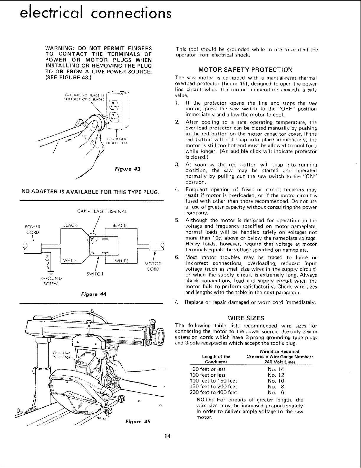
MOTOR SAFETY PROTECTION
The saw motor is equipped with a manual-reset thermal
overload protector (figure 45). designed to open the power
line circuit when the motor temperature exceeds a safe
value.
1. If the protector opens the line and stops the saw
motor, press the saw switch to the "'OFF" position
immediately and allow the nqotor to cool.
2. After cooling to a safe operating temperature, the
over-load protector can be closed manually by pushing
in the red button on the motor capacitor cover. If the
red button will not snap into place immediately, the
motor is still too hot and must be allowed to cool for a
while longer. (An audible click will indicate protector
is closed.)
3. As soon as the red button will snap into running
position, the saw may be started and operated
normally by pulling out the saw switch to the "ON"
position.
4. Frequent opening of fuses or circuit breakers may
result if motor is overloaded, or if the motor circuit is
fused with other than those recommended. Do not use
a fuse of greater capacity without consulting the power
company.
5. Although the motor is designed for operation on the
voltage and frequency specified on motor nameplate,
normal loads will be handled safely on voltages not
more than 10% above or below the nameplate voltage.
Heavy loads, however, require that voltage at motor
terminals equals the voltage specified on nameplate.
6. Most motor troubles may be traced to loose or
incorrect connections, overloading, reduced input
voltage (such as small size wires in the supply circuit)
or when the supply circuit is extremely long. Always
check connections, load and supply circuit when the
motor fails to perform satisfactorily. Check wire sizes
and lengths with the table in the next paragraph.
7. Replace or repair damaged or worn cord immediately.
Figure 45
WIRE SIZES
The following table lists recommended wire sizes for
connecting the motor to the power source. Use only 3-wire
extension cords which have 3-prong grounding type plugs
and 3-pole receptacles which accept the tool's plug.
Wire Size Required
Length of the (American Wire Gauge Number)
Conductor 240 Volt Lines
50 feet or less No. 14
100 feet or less No. 12
100 feet to 150 feet No. 10
150feet to 200feet No. 8
200 feet to 400 feet No. 6
NOTE: For circuits of greater length, the
wire size must be increased proportionately
in order to deliver ample voltage to the saw
motor.
14
Loading ...
Loading ...
Loading ...