Loading ...
Loading ...
Loading ...
fence should be at extreme rear and the blade
positioned as shown in figure 39. With 12 inches
measured between the fence (when in full rear
position) and face of saw blade, the rip-scale
indicator should be positioned to read 12 inches
on the upper portion of the "Out-Rip" scale.
NOTE: With the saw blade and fence in the
position shown in figure 39, the upper
portion of the "Out-Rip" scale is used. If the
fence is moved to normal position (at the
rear of front table) the lower portion of the
"Out-Rip" scale is used.
d. Loosen the yoke clamp handle, lift up on the
swivel latch pin knob and return the blade to the
90 ° position.
8. Installing the Guard
a. Remove the saw blade as follows:
(1) Move the carriage slightly rearward of
mid-position on radial arm and tighten the
carriage lock knob.
(2) Elevate the saw blade 30 turns of the
elevation crank.
(3) Position wrenches as shown in figure 40.
(4) Remove shaft nut, outer collar, saw blade and
inner collar.
b. Hold the guard in upside-down position and slide
it into position on the motor shaft, allowing it to
hang by the slot in the inner (clear plastic)
assembly. (See figure 41.)
c. Slide the inner collar on the motor shaft (with the
flat side facing outward), then place the saw blade
on the shaft. Make sure the teeth are pointed for
proper saw rotation.
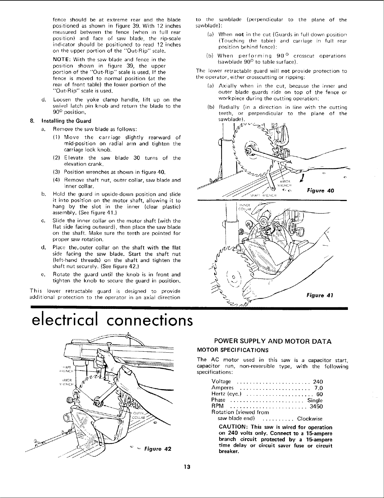
d. Place the.outer collar on the shaft with the flat
side facing the saw blade. Start the shaft nut
(left-hand threads) on the shaft and tighten the
shaft nut securely. (See figure 42.)
e. Rotate the guard until the knob is in front and
tighten the knob to secure the guard in position.
This lower retractable guard is designed to provide
additional protection to the operator in an axia! direction
to [he sawblade (perpendicular to the plane of the
sawblade):
(a) When not in the cut (Guards in full down position
(Touching the table) and carriage in ful! rear
position behind fence):
(b) When performing 90 ° crosscut operations
(sawblade 90 ° to table surface).
The lower retractable guard will not provide protection to
the operator, either crosscutting or ripping:
(a) Axially when in the cut, because the inner and
outer blade guards ride on top of the fence or
workpiece during the cutting operation;
(b) Radially (in a direction in line with the cutting
teeth, or perpendicular to the plane of the
sawblade).
Figure 41
electrical connections
¢, R NC H -
Figure 42
POWER SUPPLY AND MOTOR DATA
MOTOR SPECl FICATIONS
The AC motor used in this saw is a capacitor start,
capacitor run, non-reversible type, with the following
specifications:
Voltage ....................... 240
Amperes ...................... 7.0
Hertz (cyc.) ..................... 60
Phase ....................... Single
RPM ........................ 3450
Rotation (viewed from
saw blade end) .......... Clockwise
CAUTION: This saw is wired for operation
on 240 volts only. Connect to a 15*ampere
branch circuit protected by a 15-ampere
time delay or circuit saver fuse or circuit
breaker,
13
Loading ...
Loading ...
Loading ...