Loading ...
Loading ...
Loading ...
trouble shooting
e.
Bearings Loose on Tracks.
Adjust carriage bearings as described in subsequent
instructions.
f. Yoke Does Not Index Properly.
Check for proper yoke indexing noting that the
swivel latch pin fits into its detents properly. If
swivel latch pin housing screws (located under
left-hand carriage cover) are loose, re-adjust blade
for "heel" as described in paragraph, "Blade Heels
to the Right or Left".
g. Yoke Clamp Does Not Tighten the Yoke When In
Full Rearward Position.
Refer to paragraph, "Yoke Clamp Handle
Adjustment" in subsequent instructions,
h. Improper Indexing of Radial Arm for Miter Cuts.
Refer to paragraph, "Precision Indexing", in the
"Operation" section.
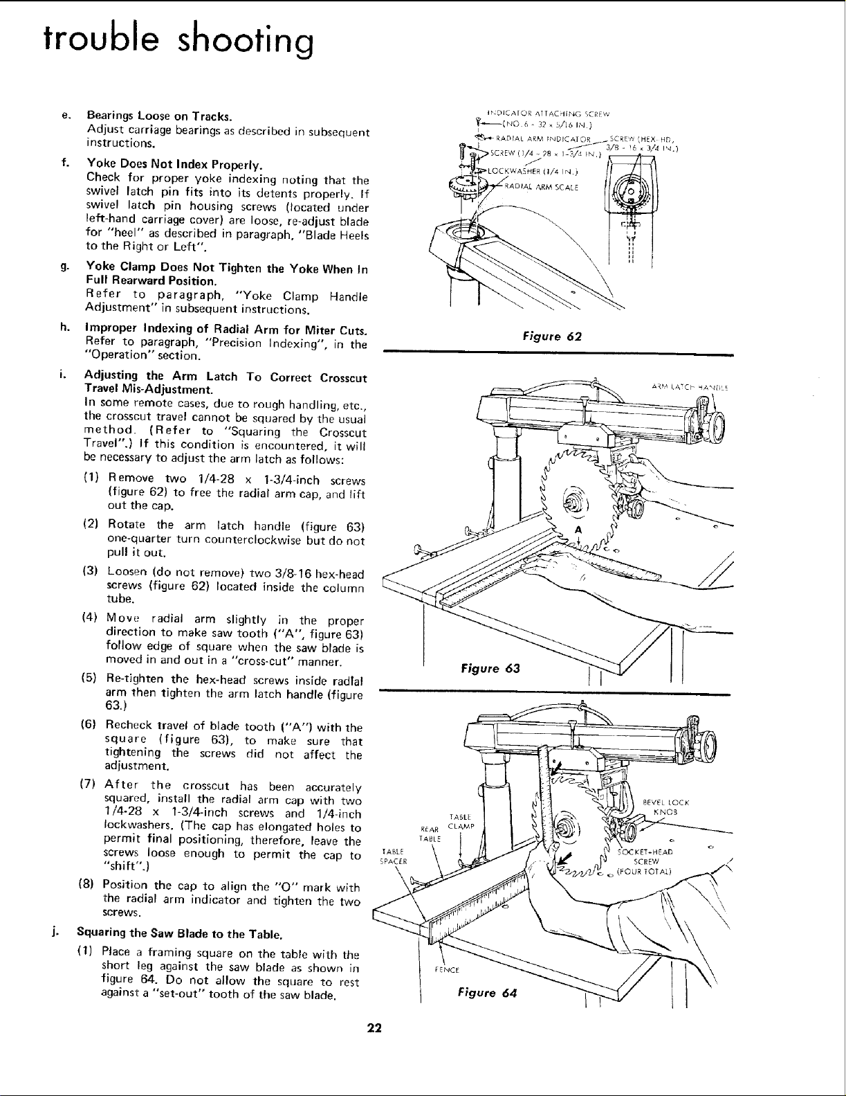
Adjusting the Arm Latch To Correct Crosscut
Travel Mis-Adjustment.
In some remote cases, due to rough handling, etc.,
the crosscut travel cannot be squared by the usual
method. (Refer to "Squaring the Crosscut
Travel".) if this condition is encountered, it will
be necessary to adjust the arm latch as follows:
(1) Remove two 1/4-28 x 1-3/4-inch screws
{figure 62} to free the radial arm cap, and lift
out the cap.
(2) Rotate the arm latch handle (figure 63)
one-quarter turn counterclockwise but do not
pull it out.
(3) Loosen (do not remove) two 3/8-16 hex-head
screws (figure 62) located inside the column
tube.
(4)
Mow. • radial arm slightly in the proper
direction to make saw tooth ("A", figure 63)
follow edge of square when the saw blade is
moved in and out in a "cross-cut" manner.
(5) Re-tighten the hex-head screws inside radial
arm then tighten the arm latch handle (figure
63.)
(6) Recheck travel of blade tooth ("A") with the
square (figure 63), to make sure that
tightening the screws did not affect the
adjustment.
(7) After the crosscut has been accurately
squared, install the radial arm cap with two
1/4-28 x 1-3/4-inch screws and 1/4-inch
Iockwashers. (The cap has elongated holes to
permit final positioning, therefore, leave the
screws loose enough to permit the cap to
"shift".)
(8) Position the cap to align the "'O" mark with
the radial arm indicator and tighten the two
screws.
Squaring the Saw Blade to the Table.
(1) Place a framing square on the table with the
short leg against the saw blade as shown in
figure 64. Do not allow the square to rest
against a "set-out" tooth of the saw blade.
Figure 62
Figure 63 t
F,:NCE
t Figure 64
22
Loading ...
Loading ...
Loading ...