Loading ...
Loading ...
Loading ...
7
3.4 ASSEMBLY OF THE CUTTING MEANS
ENGAGEMENT CONTROL LEVER EX-
TENSION (Fig. 3.3)
Fit the extension (1) onto the lever (2), position-
ing it so that the two grains (3) face the rear of
the machine, then tighten the two grains (3)
completely.
3.5 ASSEMBLING THE MOBILE COVER
Fit the mobile cover following instructions sup-
plied.
3.6 FITTING THE SEAT (Fig. 3.4)
Fit the seat (1) onto the plate (2) using the
screws (3).
3.7 ASSEMBLING THE GRASS CATCHER
(Fig. 3.5)
First of all assemble the frame, joining the upper
part (1), that includes the opening, to the lower
part (2) using the supplied screws and nuts (3)
in the indicated order.
sides, and attach them to the frame using the
four self-threading screws (6).
Insert the assembled frame in the canvas cover,
making sure it is correctly positioned on the
the frame tubes with the aid of a screw-driver
(7).
Insert the handle (8) in the cover holes (9), fas-
ten the ensemble to the frame using the screws
provided (10) in the indicated order and com-
plete the assembly with the four front and rear
self-threading screws (11).
Last of all, fasten the reinforcement bar (12) un-
canvas, using the screws and nuts provided (13)
in the indicated order.
3.8 ASSEMBLING THE SIDE PANELS OF
THE CUTTING-MEANS ASSEMBLY
(FIG. 3.6).
Assemble the two side panels right (1) and left
(2), following the assembly direction carefully
supplied.
4. CONTROLS AND INSTRUMENTS
4.1 STEERING WHEEL (Fig. 4.1 no.1)
Turns the front wheels.
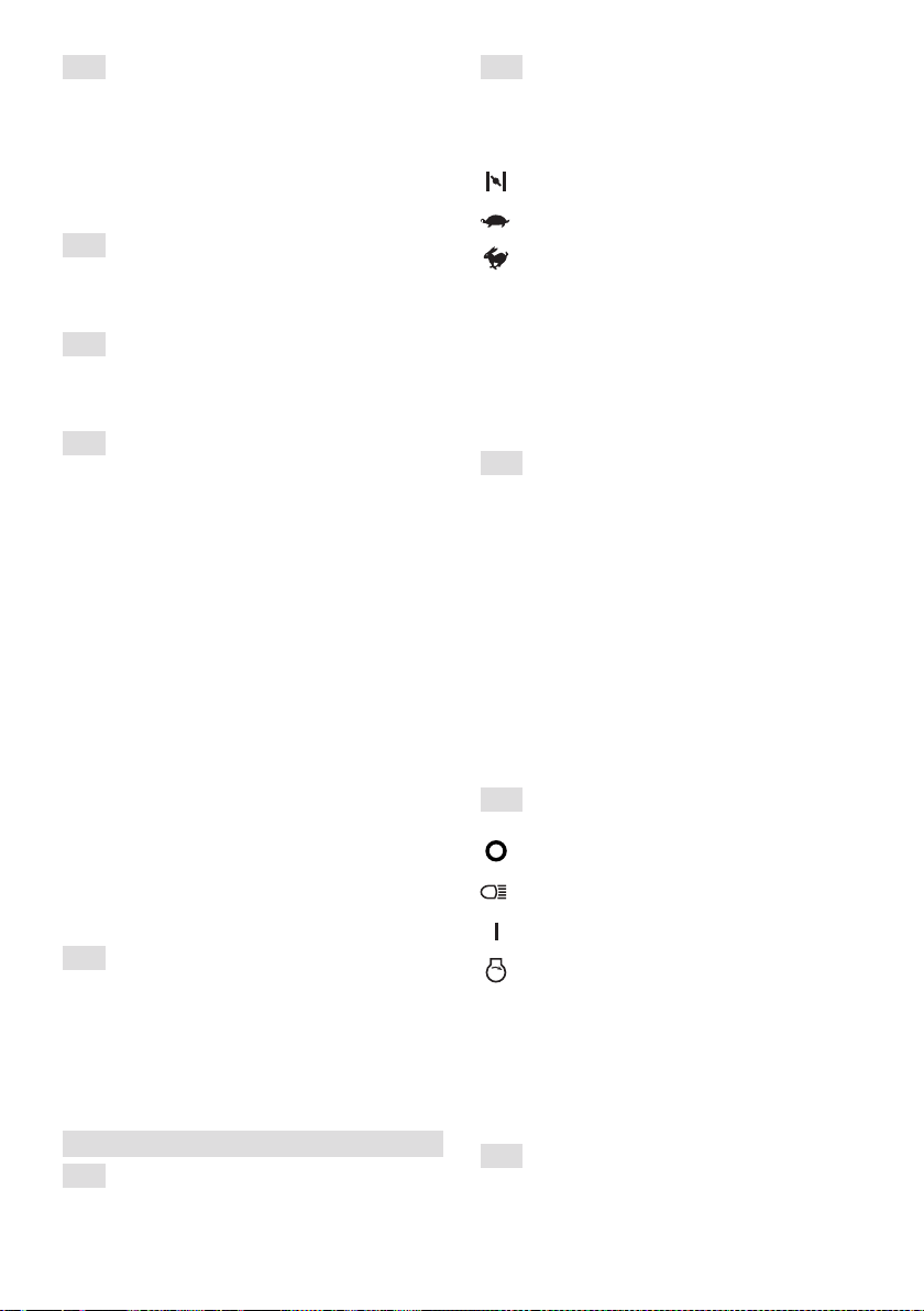
4.2 THROTTLE LEVER (Fig. 4.1 no.2)
Regulates the engine’s r.p.m. The positions are
indicated on the plate showing the following
symbols:
«CHOKE» cold start
«SLOW» for minimum engine speed
«FAST» for maximum engine speed
– The «CHOKE» position enriches the mixture
so it must only be used for the time necessary
for cold starts.
– When moving from one area to another, put
the lever in a position between «SLOW» and
«FAST».
– When cutting, shift into «FAST».
4.3 PARKING BRAKE (Fig. 4.1 no.3)
This lever stops the machine from moving when
it has been parked. There are two positions:
«A» = Brake disengaged
«B» = Brake engaged
– The brake is applied by pressing the pedal
-
it will be blocked by the lever in the lowered
position.
– To disengage the parking brake, press the
«A».
4.4 KEY IGNITION SWITCH (Fig. 4.1 no.4)
This key operated control has four positions:
«HEADLIGHTS ON»;
«ON» activates all parts;
«START» engages the starter motor.
– On being released at the «START» position,
the key will automatically return to «ON».
– After turning the engine on, turn the lights on
-
LIGHTS ON» position.
4.5 INDICATOR LAMP AND DEVICES
(Fig. 4.1 no.5)
«ON» position and stays on while the machine
Loading ...
Loading ...
Loading ...