Loading ...
Loading ...
Loading ...
SDS5000X Series Digital Oscilloscope User Manual
98 / 2 3 6 W W W. S I G L E N T. C O M
Note: "Level +/-Delta” represents half of the actual window area. For example,
when the value is 200 mV, it actually represents a range of ± 200 mV, which is
a 400 mV window.
Coupling and noise reject can be set when using the window trigger, see the
sections "Coupling”, “Noise" for details.
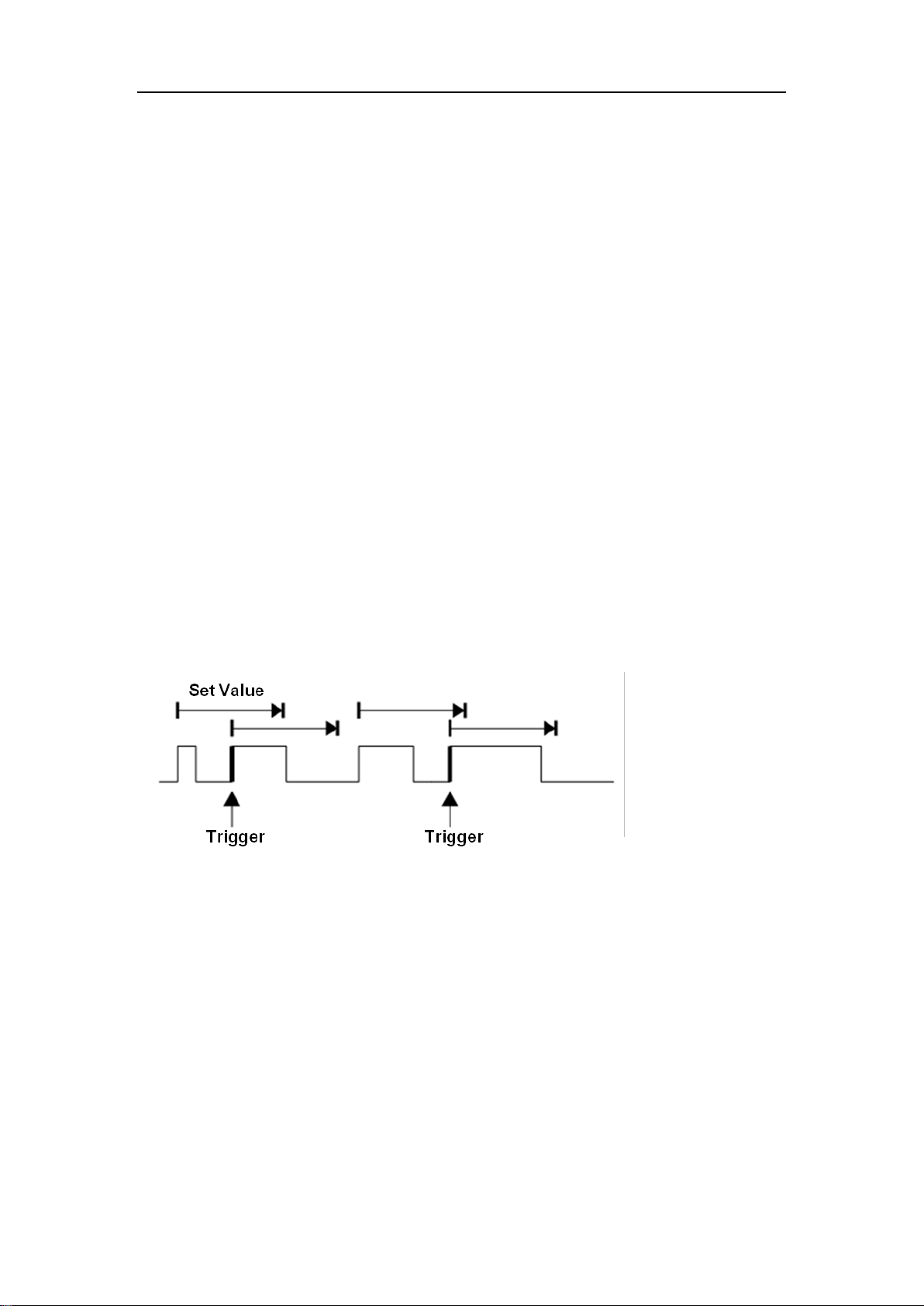
15.5.7 Interval Trigger
Trigger when the time difference between the neighboring rising or falling edges
meets the time limit condition.
When the trigger condition is set as an interval between two neighboring rising
edges and it is less than the set time value, the trigger diagram is as follows:
Trigger source, slope (rising, falling), limit range and time value can be set in
the trigger dialog box. Coupling and noise reject can be set in the interval trigger,
see the sections "Coupling” and “Noise" for details
15.5.8 Dropout Trigger
Dropout trigger includes two types: Edge and state.
Loading ...
Loading ...
Loading ...